light JAGUAR XFR 2010 1.G Workshop Manual
[x] Cancel search | Manufacturer: JAGUAR, Model Year: 2010, Model line: XFR, Model: JAGUAR XFR 2010 1.GPages: 3039, PDF Size: 58.49 MB
Page 22 of 3039

Operation and
Component DescriptionCellular PhoneComponent
Location
Overview
System Operation
and Component DescriptionNavigation SystemComponent Location
Overview
System Operation and Component DescriptionVideo SystemComponent
Location
Overview
System Operation
and Component DescriptionDiagnosis and TestingInformation and Entertainment SystemRemoval and InstallationAudio Unit
Audio Unit Antenna Amplifier
Audio and Climate Control Assembly
Front Door Speaker
Information and Entertainment Display
Information and Entertainment Module
Instrument Panel Speaker
Rear Door Speaker
Steering Wheel Audio Controls
Subwoofer Amplifier
Subwoofer Speaker
Satellite Radio Tuner415-01B: Information and Entertainment System - DTC: Audio Input Control Module
Diagnosis and TestingAudio Input Control Module417: Lighting
417-01: Exterior LightingSpecificationDescription and OperationComponent Location
Overview
System Operation and Component DescriptionDiagnosis and TestingHeadlampsGeneral ProceduresHeadlamp Adjustment (86.40.18)
Page 23 of 3039

Removal and InstallationApproach Lamp
Headlamp Assembly
Headlamp Leveling Front Sensor
Headlamp Leveling Rear Sensor
High Mounted Stoplamp
Rear Fog Lamp
Rear Lamp Assembly
Side Turn Signal Lamp417-02: Interior Lighting
Description and OperationComponent Location
Overview
System Operation and Component DescriptionDiagnosis and TestingInterior Lighting417-04: Daytime Running Lamps (DRL)
Description and OperationOverview
System Operation and Component Description418: Electrical Distribution
418-00: Module Communications Network
Description and OperationOverview
System Operation and Component DescriptionDiagnosis and TestingCommunications NetworkRemoval and InstallationAuxiliary Junction Box (AJB)
Central Junction Box (CJB)418-02: Wiring Harnesses
Description and OperationWiring HarnessGeneral ProceduresWiring Harness RepairRemoval and InstallationLuggage Compartment Lid Wiring Harness419: Electronic Feature Group
419-01A: Anti-Theft - Active
Description and OperationComponent Location
Overview
Page 45 of 3039
Published: 11-May-2011
General Information - Battery and Battery Charging Health and Safety Precautions
Description and Operation
WARNINGS:
Batteries contain sulphuric acid, avoid contact with skin, eyes or clothing. Wear safety goggles when working near the
battery to protect against possible splashing of the acid solution.
EYE CONTACT: If acid comes into contact with the eyes, flush immediately with plenty of running water for a minimum of
15 minutes. Seek immediate medical attention.
SKIN CONTACT: If acid comes into contact with the skin, flush immediately with plenty of running water for a minimum of
15 minutes. Seek immediate medical attention.
SWALLOWED: If acid is swallowed, rinse the mouth with plenty of water and then drink plenty of water or milk. Do not
induce vomiting. Seek immediate medical attention.
Batteries normally produce explosive gases. Do not allow naked flames, sparks or lighted substances to come near the
battery.
When charging the battery shield your face and wear safety goggles. Provide adequate ventilation.
CAUTION: Boost charging with excessive current or voltage above 16 volts will damage the battery.
www.JagDocs.com
Page 47 of 3039
Published: 11-May-2011
General Information - Diesel Fuel System Health and Safety Precautions
Description and Operation
WARNINGS:
Fuel may not give adequate warning before toxic or harmful effects arise.
Exposure to fuel can be harmful and can cause severe health damage or death.
Provide adequate ventilation when working on fuel systems.
Extreme care must be exercised when handling hot fluids. Always wash off spilled fluids from affected areas of skin
immediately.
Fuel must not be used as a cleaning agent.
Keep fuel containers tightly closed, out of direct sunlight and in a cool area. Keep away from heat sources, ignition
sources and oxidizing agents.
SKIN CONTACT: Fuel is mildly irritating to the skin and may cause dermatitis due to defatting effect. Remove
contaminated clothing. Wash affected areas of skin with soap and water. Seek medical attention for any persistent skin
irritation or abnormality. Wash contaminated clothing before reuse.
SKIN CONTACT: Excessive or prolonged skin contact with diesel fuel may cause serious skin disorders including skin
cancer.
EYE CONTACT: Fuel is mildly irritating to the eyes. Flush with plenty of running water, blinking as often as possible. Do
not force the eyelid open. Seek medical attention for any persistent eye irritation or abnormality.
SWALLOWED: Fuel is moderately toxic and tends to foam on vomiting. If drawn into the lungs, inflammation may
develop. Do not induce vomiting. If spontaneous vomiting occurs place the victim in a forward position to reduce the risk of
fuel being drawn into the lungs. Give nothing by mouth. If breathing but unconscious, place in the recovery position. If
breathing has stopped, apply artificial respiration. Seek immediate medical attention.
INHALED: Fuel is toxic to the respiratory and other body systems. Exposure may result in various symptoms including
drowsiness, unconsciousness or severe health damage. Move a victim to fresh air. Keep a victim warm and at rest. If
unconscious, place in the recovery position. If not breathing, apply artificial respiration. Give cardiac massage if necessary.
Seek immediate medical attention.
CAUTIONS:
Fuel injection equipment is manufactured to very precise tolerances and fine clearances. It is essential that absolute
cleanliness is observed when working with these components.
Make sure that the workshop area in which the vehicle is being worked on is as clean and as dust free as possible.
Make sure that non-plated tools are used.
Tools must be cleaned using a new brush and fresh suitable evaporative cleaning agent.
Make sure to use a steel topped workbench covered with clean, lint-free, non-flocking material.
Make sure that all parts removed from the vehicle are placed on the lint-free, non-flocking material.
Make sure that any protective clothing worn is clean and made from lint-free, non-flocking material.
Page 50 of 3039
disconnected, a Radio Code Saver will allow sufficient current to pass to maintain the radio receiver/cassette player/mini disc
player and compact disc player memory, operate the clock and supply the door operated interior lights while isolating the
battery in the event of a short circuit.
Reconnecting the Battery
WARNING: If the battery has been on bench charge the cells may be giving off explosive hydrogen gas. Avoid creating
sparks, and if in doubt cover the vent plugs or covers with a damp cloth.
Always make sure that all electrical systems are switched OFF before reconnecting the battery to avoid causing sparks or
damage to sensitive electrical equipment.
Always reconnect the battery positive lead first and the negative last, ensuring that there is a good electrical contact and the
battery terminals are secure.
Restart the clock (where installed) and set it to the correct time.
Enter the radio receiver/cassette player/mini disc player and compact disc player keycodes and preset' frequencies, if known.
Following reconnection of the battery, the engine should be allowed to idle until it has reached normal operating temperature
as the stored idle and drive values contained within the ECM have been lost. Allow the vehicle to idle for a further three
minutes. Drive the vehicle at constant speeds of approximately 48 km/h (30 mph), 64 km/h (40 mph), 80 km/h (50 mph), 96
km/h (60 mph) and 112 km/h (70 mph) for three minutes each. This will allow the ECM to relearn idle and drive values, and
may cause driveability concerns if the procedure is not carried out.
Connecting a Slave Battery Using Jump Leads
WARNING: If the slave battery has recently been charged and is gassing, cover the vent plugs or covers with a damp
cloth to reduce the risk of explosion should arcing occur when connecting the jump leads.
CAUTIONS:
A discharged battery condition may have been caused by an electrical short circuit. If this condition exists there will be
an apparently live circuit on the vehicle even when all circuits are switched off. This can cause arcing when the jump leads are
connected.
Whilst it is not recommended that the vehicle is jump started, it is recognized that this may occasionally be the only
practical way to mobilize a vehicle. In such an instance the discharged battery must be recharged immediately after jump
starting to avoid permanent damage.
Always make sure that the jump leads are adequate for the task. Heavy duty cables must be used.
Always make sure that the slave battery is of the same voltage as the vehicle battery. The batteries must be connected
in parallel.
Always make sure that switchable electric circuits are switched off before connecting jump leads. This reduces the risk
of sparks occurring when the final connection is made.
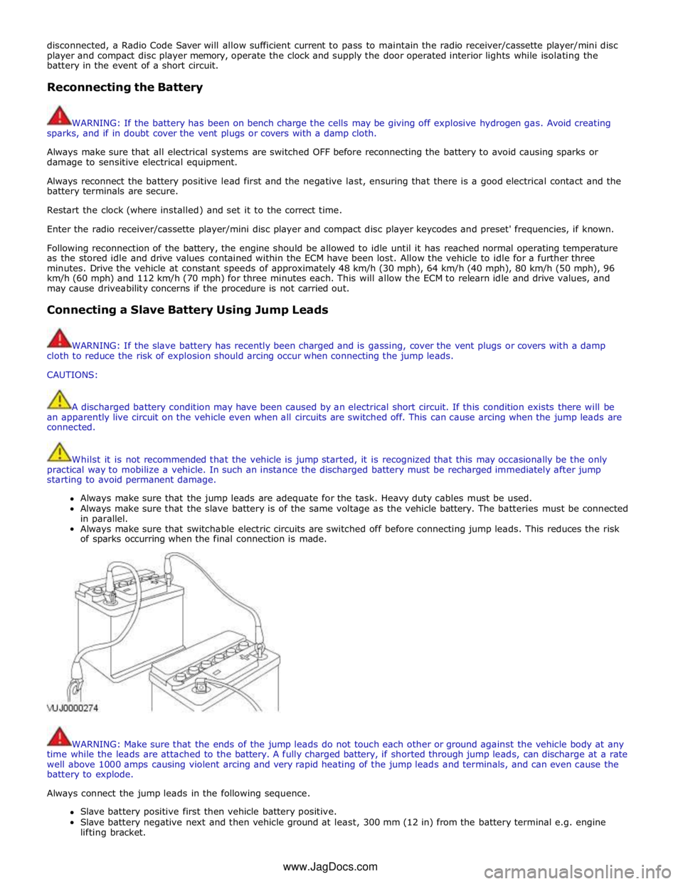
WARNING: Make sure that the ends of the jump leads do not touch each other or ground against the vehicle body at any
time while the leads are attached to the battery. A fully charged battery, if shorted through jump leads, can discharge at a rate
well above 1000 amps causing violent arcing and very rapid heating of the jump leads and terminals, and can even cause the
battery to explode.
Always connect the jump leads in the following sequence.
Slave battery positive first then vehicle battery positive.
Slave battery negative next and then vehicle ground at least, 300 mm (12 in) from the battery terminal e.g. engine
lifting bracket. www.JagDocs.com
Page 54 of 3039

Hydrofluorocarbon HFC High tension HT Hydrocarbon HC Idle Air Control IAC
Stepper motor driven device which varies the volume of air by-passing the
throttle to maintain the programmed idle speed Intake Air Temperature IAT Temperature of intake air Inertia Fuel Shut-off IFS
An inertia system that shuts off the fuel supply when activated by pre-determined force limits brought about by (e.g.) collision Input Shaft Speed ISS Indicates input shaft speed Key On, Engine Off KOEO Key On, Engine Running KOER Kilogram (mass) kg Kilogram (force) kgf Kilogram force per square
centimeter kgf/cm²
Kilometer km Kilometer per hour km/h Kilopascal kPa Kilovolt kV Knock Sensor KS
Sensor which detects the onset of detonation, and signals the ECM to
retard the ignition Liquid Crystal Display LCD
Optical digital display system, to which applied voltage varies the way the crystals reflect light, thereby modifying the display Lighting Control Module LCM Light Emitting Diode LED Low Tension LT
Primary circuit of the ignition system, linking the battery to the primary winding in the ignition coil Left-Hand LH Left-Hand Drive LHD Mass Air Flow MAF
System which provides information on the mass flow rate of the intake air
to the engine Manifold Absolute Pressure MAP Absolute pressure of the intake manifold air Manifold Absolute Pressure and Temperature MAPT
Malfunction Indicator Lamp MIL
A required on-board indicator to alert the driver of an emission related
malfunction Meter (measurement) m Metric (screw thread, e.g. M8) M Farad F Unit of electrical capacitance Millimeter mm Millimeter of mercury mmHg Millisecond ms Model year MY Newton N SI unit of force. 1 N = 0.2248 pounds force Newton Meter Nm SI unit of torque. Must not be confused with nm (nanometer) Negative Temperature
Coefficient NTC
Naturally aspirated N/A
Fuelling system using intake air at atmospheric pressure; not supercharged or turbocharged Noise, Vibration and Harshness NVH North American Specification NAS Vehicles for sale in the USA and Canadian markets On-Board Diagnostic OBD
A system that monitors some or all computer input and output control
signals. Signal(s) outside the pre-determined limits imply a fault in the system or a related system Oxides of Nitrogen Nox Oxygen Sensor O2S A sensor which detects oxygen content in the exhaust gases On-board Refuelling Vapour Recovery ORVR
Output State Control OSC Output Shaft Speed OSS Passenger Air Bag Deactivation PAD Pulsed Secondary Air Injection PAIR Passive Anti-Theft System PATS Positive Crankcase Ventilation PCV Parameter Identification PID
An index number referring to a parameter within a module without knowledge of its storage location Park/Neutral Position PNP Pulse Width Modulation PWM Programmable Electronic
Control Units System PECUS
Process whereby a common ECM is programmed on the production line to
suit the market requirements of a particular vehicle
Page 64 of 3039

Viton
In common with many other manufacturers' vehicles, some components installed to the Jaguar range have 'O' rings, seals or
gaskets which contain a material known as 'Viton'.
Viton is a fluoroelastomer, that is a synthetic rubber type which contains Fluorine. It is commonly used for 'O' rings, gaskets
and seals of all types. Although Viton is the most well known fluoroelastomer, there are others, including Fluorel and
Tecmoflon.
When used under design conditions fluoroelastomers are perfectly safe. If, however, they are exposed to temperatures in
excess of 400º C, the material will not burn, but will decompose, and one of the products formed is hydrofluoric acid.
This acid is extremely corrosive and may be absorbed directly, through contact, into the body.
'O' rings, seals or gaskets which have been exposed to very high temperatures will appear charred or as a black sticky
substance.
DO NOT, under any circumstances touch them or the attached components.
Enquiries should be made to determine whether Viton or any other fluoroelastomer has been used in the affected 'O' ring, seal
or gasket. If they are of natural rubber or nitrile there is no hazard. If in doubt, be cautious and assume that the material may
be Viton or any fluoroelastomer.
If Viton or any other fluoroelastomers have been used, the affected area should be decontaminated before the commencement
of work.
Disposable heavy duty plastic gloves should be worn at all times, and the affected area washed down using wire wool and a
limewater (calcium hydroxide) solution to neutralize the acid before disposing of the decomposed Viton residue and final
cleaning of the area. After use, the plastic gloves should be discarded carefully and safely.
Welding
See also Fire, Electric Shock, Gas Cylinders.
Welding processes include Resistance Welding (Spot Welding), Arc Welding and Gas Welding (and cutting).
Resistance Welding (Spot Welding)
This process may cause particles of molten metal to be emitted at a high velocity, and the eyes and skin must be protected.
Arc Welding
This process emits a high level of ultraviolet radiation which may cause arc-eye and skin burns to the operator and to other
persons nearby. Gas-shielded welding processes are particularly hazardous in this respect. Personal protection must be worn,
and screens used to shield other people.
CONTACT LENS WEARERS ARE ADVISED TO REVERT TO ORDINARY SPECTACLES WHEN ARC WELDING as the arc spectrum is
believed to emit microwaves which dry out the fluid between the lens and the eye. This may result in blindness when the lens
is removed from the eye.
Metal spatter will also occur, and appropriate eye and skin protection is necessary.
The heat of the welding arc will produce fumes and gases from the metals being welded, the rods and from any applied
coatings or contamination on the surfaces being worked on. These gases and fumes may be toxic and inhalation of these
should be avoided. The use of extraction ventilation to remove the fumes from the working area may be necessary particularly
in cases where the general ventilation is poor, or where considerable welding work is anticipated. In extreme cases or confined
spaces where adequate ventilation cannot be provided, air-fed respirators may be necessary.
Gas Welding (and Cutting)
Oxy-acetylene torches may be used for welding and cutting, and special care must be taken to prevent leakage of these gases,
with consequent risk of fire and explosion.
The process will produce metal spatter and eye and skin protection is necessary.
The flame is bright, and eye protection should be used, but the ultraviolet emission is much less than that from arc welding,
and lighter filters may be used.
The process itself produces few toxic fumes, but such fumes and gases may be produced from coatings on the work,
particularly during cutting away of damaged body parts, and inhalation of the fumes should be avoided.
In brazing, toxic fumes may be produced from the metals in the brazing rod, and a severe hazard may arise if brazing rods
containing cadmium are used. In this event particular care must be taken to avoid inhalation of fumes and expert advice may
be required.
SPECIAL PRECAUTIONS MUST BE TAKEN BEFORE ANY WELDING OR CUTTING TAKES PLACE ON VESSELS WHICH HAVE
CONTAINED COMBUSTIBLE MATERIALS, E.G. BOILING OR STEAMING OUT OF FUEL TANKS.
Warning Symbols on Vehicles
Decals showing warning symbols will be found on various vehicle components.
Page 66 of 3039
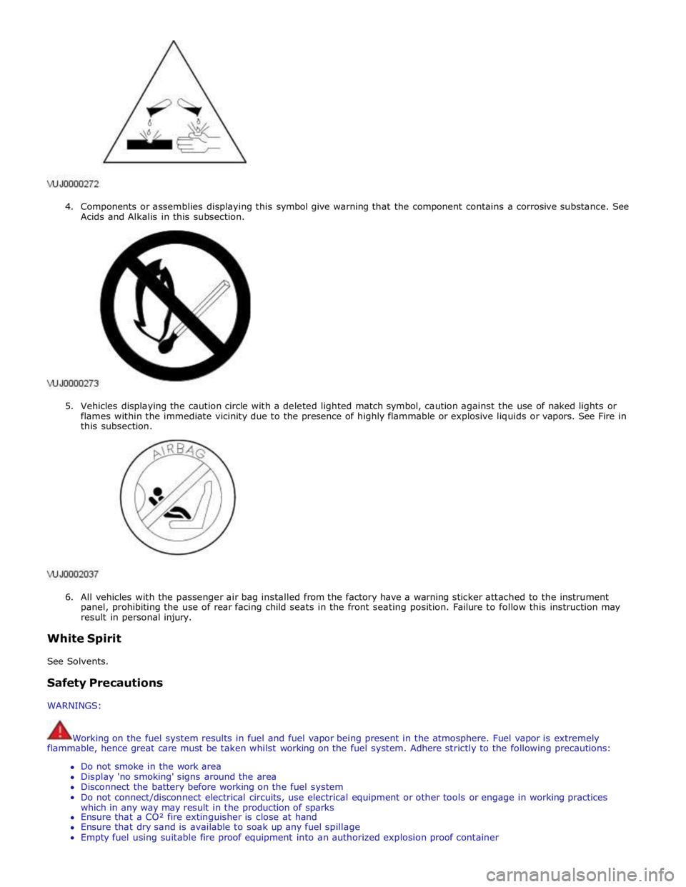
4. Components or assemblies displaying this symbol give warning that the component contains a corrosive substance. See
Acids and Alkalis in this subsection.
5. Vehicles displaying the caution circle with a deleted lighted match symbol, caution against the use of naked lights or
flames within the immediate vicinity due to the presence of highly flammable or explosive liquids or vapors. See Fire in
this subsection.
6. All vehicles with the passenger air bag installed from the factory have a warning sticker attached to the instrument
panel, prohibiting the use of rear facing child seats in the front seating position. Failure to follow this instruction may
result in personal injury.
White Spirit
See Solvents.
Safety Precautions
WARNINGS:
Working on the fuel system results in fuel and fuel vapor being present in the atmosphere. Fuel vapor is extremely
flammable, hence great care must be taken whilst working on the fuel system. Adhere strictly to the following precautions:
Do not smoke in the work area
Display 'no smoking' signs around the area
Disconnect the battery before working on the fuel system
Do not connect/disconnect electrical circuits, use electrical equipment or other tools or engage in working practices
which in any way may result in the production of sparks
Ensure that a CO² fire extinguisher is close at hand
Ensure that dry sand is available to soak up any fuel spillage
Empty fuel using suitable fire proof equipment into an authorized explosion proof container
Page 70 of 3039
Published: 11-May-2011
General Information - Petrol and Petrol-Ethanol Fuel Systems Health and
Safety Precautions
Description and Operation
WARNINGS:
Fuel may not give adequate warning before toxic or harmful effects arise.
Exposure to fuel can be harmful and can cause severe health damage or death.
Extreme care must be exercised when handling hot fluids. Always wash off spilled fluids from affected areas of skin
immediately.
Highly flammable mixtures are always present and may ignite when working on fuel systems. Do not allow naked flames,
sparks or lighted substances to come near fuel related components.
Fuel must not be used as a cleaning agent.
Keep fuel containers tightly closed, out of direct sunlight and in a cool area. Keep away from heat sources, ignition
sources and oxidizing agents.
SKIN CONTACT: Excessive or prolonged skin contact with diesel fuel may cause serious skin disorders including skin
cancer.
SKIN CONTACT: Fuel is mildly irritating to the skin and may cause dermatitis due to defatting effect. Remove
contaminated clothing. Wash affected areas of skin with soap and water. Seek medical attention for any persistent skin
irritation or abnormality. Wash contaminated clothing before reuse.
EYE CONTACT: Fuel is mildly irritating to the eyes. Flush with plenty of running water, blinking as often as possible. Do
not force the eyelid open. Seek medical attention for any persistent eye irritation or abnormality.
SWALLOWED: Fuel is moderately toxic and tends to foam on vomiting. If drawn into the lungs, inflammation may
develop. Do not induce vomiting. If spontaneous vomiting occurs place the victim in a forward position to reduce the risk of
fuel being drawn into the lungs. Give nothing by mouth. If breathing but unconscious, place in the recovery position. If
breathing has stopped, apply artificial respiration. Seek immediate medical attention.
INHALED: Fuel is toxic to the respiratory and other body systems. Exposure may result in various symptoms including
drowsiness, unconsciousness or severe health damage. Move a victim to fresh air. Keep a victim warm and at rest. If
unconscious, place in the recovery position. If not breathing, apply artificial respiration. Give cardiac massage if necessary.
Seek immediate medical attention.
CAUTIONS:
Fuel injection equipment is manufactured to very precise tolerances and fine clearances. It is essential that absolute
cleanliness is observed when working with these components.
Make sure that the workshop area in which the vehicle is being worked on is as clean and as dust free as possible.
www.JagDocs.com
Page 103 of 3039
General Information - Road/Roller Testing
Description and Operation Published: 11-May-2011
Road or roller testing may be carried out for various reasons and a procedure detailing pre-test checks, through engine starting
and stopping, pre-driving checks, on-test checks to final checks on completion of the test is given in this section.
Unless complete vehicle performance is being checked, the full road test procedure need not be carried out. Instead, those
items particularly relevant to the system/s being checked can be extracted.
Pre - Test Checks
WARNING: If the brake system hydraulic fluid level is low, pedal travel is excessive or a hydraulic leak is found, do not
attempt to road test the vehicle until the reason for the low fluid level, excessive pedal travel or hydraulic leak is found and
rectified.
It is suggested that pre-test checks, and functional tests of those systems/circuits which affect the safe and legal operations
of the vehicle, such as brakes, lights and steering, should always be carried out before the road or roller test.
Engine oil level
Engine coolant level
Tires, for correct pressure, compatible types and tread patterns, and wear within limits
There is sufficient fuel in the tank to complete the test
All around the engine, transmission and under the vehicle for oil, coolant, hydraulic and fuel leaks. Make a note of any
apparent leaks and wipe off the surrounding areas to make it easier to identify the extent of the leak on completion of
the test
Starting the Engine
CAUTION: On initial drive away from cold and within the first 1.5 km (1 mile), do not depress accelerator pedal beyond
half travel until the vehicle has attained a minimum speed of 25 km/h (15 miles/h). Never operate at high engine speed or
with the accelerator pedal at full travel whilst the engine is cold.
With the ignition switched off, check:
The parking brake is applied
The transmission selector lever is in Park
All instrument gauges (except fuel gauge) read zero
With the ignition switched on, check:
Ignition controlled warning lamps come on
Engine coolant temperature gauge registers a reading compatible with the engine coolant temperature
Fuel gauge registers a reading appropriate to the fuel level in the tank
The operation of the parking brake and brake fluid level warning lamps
On Road or Roller Test Check:
CAUTION: If road testing, check the brake operation while still travelling at low speed before continuing with the test. If
the brakes pull to one side, or appear to be otherwise faulty, do not continue with the road test until the fault has been found
and rectified.
Initial gear engagement is smooth
Parking brake control operates smoothly and the parking brake releases quickly and completely
Transmission takes up the drive smoothly, without judder
The engine power output is satisfactory, full power is achieved, acceleration is smooth and pedal operation not stiff or
heavy, and engine speed returns to idle correctly
There is no excessive or abnormally colored smoke from the engine under normal driving, heavy load or overrun
conditions
Steering operation, including power steering, is smooth, accurate, not excessively heavy or with excessive free play or
vibration. Does not pull to one side and self centres smoothly after cornering
Speedometer, oil pressure warning lamp, coolant temperature gauge and tachometer register the correct readings or
operate correctly
Switches and controls operate smoothly and positively, warning lamps operate correctly and the direction indicator
control self cancels when the steering is returned to the straight ahead position
Heating and ventilation systems work correctly and effectively
Brake operation and efficiency
Brake Testing
WARNING: When brake testing, avoid breathing the smoke or fumes from hot brakes, this may contain asbestos dust
which is hazardous to health, see Health and Safety Precautions.