seat recline motor JAGUAR XFR 2010 1.G Workshop Manual
[x] Cancel search | Manufacturer: JAGUAR, Model Year: 2010, Model line: XFR, Model: JAGUAR XFR 2010 1.GPages: 3039, PDF Size: 58.49 MB
Page 154 of 3039

DTC Description Possible Causes Action B1B86-11
Seat Height Motor Relay -
Circuit short to ground
Driver seat parallel height
motor circuit - short to ground
Carry out any pinpoint tests associated
with this DTC using the manufacturer
approved diagnostic system. Refer to the
electrical circuit diagrams and check driver
seat parallel height motor circuit for short
to ground B1B86-15
Seat Height Motor Relay -
Circuit short to battery or
open
Driver seat parallel height
motor circuit - short to power,
open circuit
Carry out any pinpoint tests associated
with this DTC using the manufacturer
approved diagnostic system. Refer to the
electrical circuit diagrams and check driver
seat parallel height motor circuit for short
to power, open circuit B1B87-31
Seat Height Motor
Speed/Position Sensor - No
signal
Harness/connector problem
No signal from sensor
Sensor/motor malfunction
Check the seat wiring harness/connectors
for security/integrity
Refer to the electrical circuit diagrams and
check the seat height motor sensor circuit.
Repair circuit as required. Clear DTC and
retest B1B88-11
Seat Slide Motor Relay -
Circuit short to ground
Driver seat slide motor circuit -
short to ground
Carry out any pinpoint tests associated
with this DTC using the manufacturer
approved diagnostic system. Refer to the
electrical circuit diagrams and check driver
seat slide motor circuit for short to ground B1B88-15
Seat Slide Motor Relay -
Circuit short to battery or
open
Driver seat slide motor circuit -
short to power, open circuit
Carry out any pinpoint tests associated
with this DTC using the manufacturer
approved diagnostic system. Refer to the
electrical circuit diagrams and check driver
seat slide motor circuit for short to power,
open circuit B1B89-31
Seat Slide Motor
Speed/Position Sensor - No
signal
Harness/connector problem
No signal from sensor
Sensor/motor malfunction
Check the seat wiring harness/connectors
for security/integrity
Refer to the electrical circuit diagrams and
check the seat slide motor speed sensor
circuit. Repair circuit as required. Clear DTC
and retest B1B90-11
Seat Tilt Motor Relay -
Circuit short to ground
Driver seat tilt motor circuit -
short to ground
Carry out any pinpoint tests associated
with this DTC using the manufacturer
approved diagnostic system. Refer to the
electrical circuit diagrams and check driver
seat tilt motor circuit for short to ground B1B90-15
Seat Tilt Motor Relay -
Circuit short to battery or
open
Driver seat tilt motor circuit -
short to power, open circuit
Carry out any pinpoint tests associated
with this DTC using the manufacturer
approved diagnostic system. Refer to the
electrical circuit diagrams and check driver
seat tilt motor circuit for short to power,
open circuit B1B91-31
Seat Tilt Motor
Speed/Position Sensor - No
signal
Harness/connector problem
No signal from sensor
Sensor/motor malfunction
Check the seat wiring harness/connectors
for security/integrity
Refer to the electrical circuit diagrams and
check the seat tilt motor speed sensor
circuit. Repair circuit as required. Clear DTC
and retest B1B92-11
Seat Recline Motor Relay -
Circuit short to ground
Driver seat recline motor
circuit - short to ground
Carry out any pinpoint tests associated
with this DTC using the manufacturer
approved diagnostic system. Refer to the
electrical circuit diagrams and check driver
seat recline motor circuit for short to
ground
Page 155 of 3039

DTC Description Possible Causes Action B1B92-15
Seat Recline Motor Relay -
Circuit short to battery or
open
Driver seat recline motor
circuit - short to power, open
circuit
Carry out any pinpoint tests associated
with this DTC using the manufacturer
approved diagnostic system. Refer to the
electrical circuit diagrams and check driver
seat recline motor circuit for short to
power, open circuit B1B93-31
Seat Recline Motor
Speed/Position Sensor - No
signal
Harness/connector problem
No signal from sensor
Sensor/motor malfunction
Check the seat wiring harness/connectors
for security/integrity
Refer to the electrical circuit diagrams and
check the seat recline motor speed sensor
circuit. Repair circuit as required. Clear DTC
and retest B1B94-24
Seat Height Up Switch -
Signal stuck high
Signal stuck high
Check for a stuck switch. Refer to the
electrical circuit diagrams and check driver
seat switch pack to seat module LIN circuit
for short, open circuit and seat height up
circuit for short to ground B1B95-24
Seat Height Down Switch -
Signal stuck high
Signal stuck high
Check for a stuck switch. Refer to the
electrical circuit diagrams and check driver
seat switch pack to seat module LIN circuit
for short, open circuit and seat height
down circuit for short to ground B1B96-24
Seat Slide Forward Switch -
Signal stuck high
Signal stuck high
Check for a stuck switch. Refer to the
electrical circuit diagrams and check driver
seat switch pack to seat module LIN circuit
for short, open circuit and seat slide
forward circuit for short to ground B1B97-24 Seat Slide Backward Switch
- Signal stuck high
Signal stuck high
Check for a stuck switch. Refer to the
electrical circuit diagrams and check driver
seat switch pack to seat module LIN circuit
for short, open circuit and seat slide
backward circuit for short to ground B1B98-24
Seat Tilt Up Switch - Signal
stuck high
Signal stuck high
Check for a stuck switch. Refer to the
electrical circuit diagrams and check driver
seat switch pack to seat module LIN circuit
for short, open circuit and seat tilt up
circuit for short to ground B1B99-24
Seat Tilt Down Switch -
Signal stuck high
Signal stuck high
Check for a stuck switch. Refer to the
electrical circuit diagrams and check driver
seat switch pack to seat module LIN circuit
for short, open circuit and seat tilt down
circuit for short to ground B1C00-24
Seat Recline Up Switch -
Signal stuck high
Signal stuck high
Check for a stuck switch. Refer to the
electrical circuit diagrams and check driver
seat switch pack to seat module LIN circuit
for short, open circuit and seat recline up
circuit for short to ground B1C01-24
Seat Recline Down Switch -
Signal stuck high
Signal stuck high
Check for a stuck switch. Refer to the
electrical circuit diagrams and check driver
seat switch pack to seat module LIN circuit
for short, open circuit and check seat
recline down circuit for short to ground B1C02-24
Memory Store Switch -
Signal stuck high
Signal stuck high
Check for a stuck switch. Refer to the
electrical circuit diagrams and check driver
seat switch pack to seat module LIN circuit
for short, open circuit www.JagDocs.com
Page 2308 of 3039

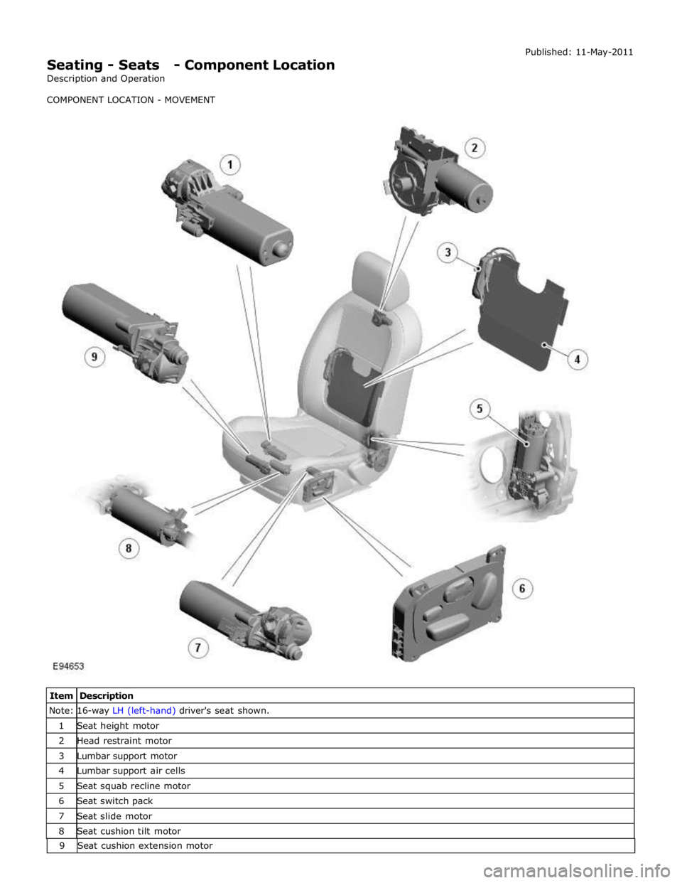
Seating - Seats - Component Location
Description and Operation
COMPONENT LOCATION - MOVEMENT Published: 11-May-2011
Item Description Note: 16-way LH (left-hand) driver's seat shown. 1 Seat height motor 2 Head restraint motor 3 Lumbar support motor 4 Lumbar support air cells 5 Seat squab recline motor 6 Seat switch pack 7 Seat slide motor 8 Seat cushion tilt motor 9Seatcushionextension motor
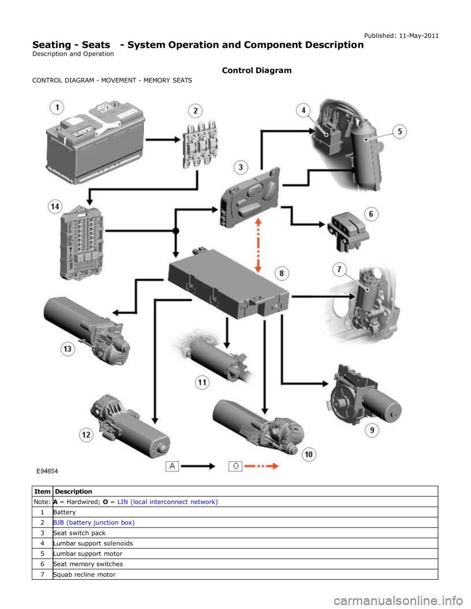
Page 2312 of 3039

Note: A = Hardwired; O = LIN (local interconnect network) 1 Battery 2 BJB (battery junction box) 3 Seat switch pack 4 Lumbar support solenoids 5 Lumbar support motor 6 Seat memory switches 7 Squab recline motor
Page 2315 of 3039

7 Front seat climate control module 8 Passenger seat squab climate module 9 Drivers seat cushion climate module 10 Passenger seat cushion climate module 11 Drivers seat squab climate module 12 Passenger seat cushion heater element 13 Passenger seat squab heater element 14 Drivers seat cushion heater element 15 Drivers seat squab heater element 16 CJB
HEATED SEATS - OPERATION
Heated Front Seats System Operation
The TSD receives a fused power supply from the RJB. One of the 3 seat heat temperature selections made by the driver or passenger using the TSD soft keys are passed from the TSD on the MOST ring to the Information and Entertainment module.
The information and entertainment module processes the information and transmits the request on the medium speed CAN bus to the ATC module.
The cushion heaters have a thermal sensor which supplies a feed back signal back to the CJB. The squab heater elements do not have a thermal sensor and are maintained at the same temperature as the seat cushion elements.
The ATC module reacts to the driver request information received from the information and entertainment module and requests the CJB to activate the seat heaters. The CJB measures the returned temperature signals from the thermal sensors and relays the temperature signals back to the ATC module. The ATC module then uses the measured seat element temperatures to provide closed-loop control of the heater elements to maintain the temperature at one the 3 heat ranges selected.
NOTE: To prevent excessive battery discharge, the heated front seats will only operate when the engine is running.
Heated and Cooled Front Seats
The TSD receives a fused power supply from the RJB. Selections made by the driver using the TSD soft keys are passed from the TSD on the MOST ring to the Information and Entertainment module. The information and entertainment module processes
the information and transmits the request on the medium speed CAN bus to the front seat climate control module. The front seat climate control module is located beneath the RH (right-hand) front seat, on the floor cross member.
The front seat climate control module receives its power supplies from the CJB. Heating and cooling requests are generated using the soft buttons on the TSD. These requests are transmitted to the information and entertainment module over the
MOST ring. The Information and Entertainment module forwards these requests to the front seat climate control module over
the medium speed CAN bus.
The front seat climate control module supplies power to the two climate modules in each seat. The temperature sensor in each
climate module is monitored by the front seat climate control module which uses the temperature information to control the
Peltier cells accordingly and also the blower fans to distribute the heated or cooled air.
NOTE: To prevent excessive battery discharge, the heated and cooled front seats will only operate when the engine is
running.
Electric Driver's Seat Adjustment - Non-Memory Seats
The CJB supplies 3 power supplies to the driver's seat switchpack. The fused supplies provide power for the seat height and squab recline, the seat slide and seat tilt and the lumbar adjustment respectively. The CJB only provides the power to the driver's seat switch pack when the ignition is on (power mode 6).
For the seat movement motors, when the applicable switch is operated, the power is supplied to the applicable side of the
motor and the ground path is completed to operate the motor in the required direction. To move the motor in the opposite
direction the polarity is reversed.
For the lumbar adjustment, when the switch is operated in the inflate position, power is supplied to the pump motor to inflate
the lumbar support. When the switch is operated in the opposite direction, the power energizes a solenoid which in turn opens
a valve to deflate the lumbar support.
Electric Passenger Seat Adjustment ( 8, 10 and 12 way)
The CJB supplies 3 power supplies to the passenger seat switchpack. The fused supplies provide power for the seat height and squab recline, the seat slide and seat tilt and the head restraint and lumbar adjustment respectively. The CJB only provides the power to the passenger seat switch pack when the ignition is on (power mode 6).
For the seat movement and head restraint motors, when the applicable switch is operated, the power is supplied to the
applicable side of the motor and the ground path is completed to operate the motor in the required direction. To move the
Page 2332 of 3039

DTC Description Possible Cause Action B1B8731
Seat Height Motor
Speed/Position
Sensor
Harness/connector problem
No signal from sensor
Sensor/motor malfunction
Check the seat wiring harness/connectors for
security/integrity
Refer to the electrical circuit diagrams and check
the seat height motor sensor circuit. Repair
circuit as required. Clear DTC and retest B1B8811
Seat Slide Motor
Relay
Driver seat slide motor circuit -
short to ground Carry out any pinpoint tests associated with this DTC
using the manufacturer approved diagnostic system.
Refer to the electrical circuit diagrams and check driver
seat slide motor circuit for short to ground B1B8815
Seat Slide Motor
Relay
Driver seat slide motor circuit -
short to power, open circuit Carry out any pinpoint tests associated with this DTC
using the manufacturer approved diagnostic system.
Refer to the electrical circuit diagrams and check driver
seat slide motor circuit for short to power, open circuit B1B8931
Seat Slide Motor
Speed/Position
Sensor
Harness/connector problem
No signal from sensor
Sensor/motor malfunction
Check the seat wiring harness/connectors for
security/integrity
Refer to the electrical circuit diagrams and check the seat slide motor speed sensor circuit. Repair circuit as required. Clear DTC and retest B1B9011
Seat Tilt Motor
Relay
Driver seat tilt motor circuit -
short to ground Carry out any pinpoint tests associated with this DTC
using the manufacturer approved diagnostic system.
Refer to the electrical circuit diagrams and check driver
seat tilt motor circuit for short to ground B1B9015
Seat Tilt Motor
Relay
Driver seat tilt motor circuit -
short to power, open circuit Carry out any pinpoint tests associated with this DTC
using the manufacturer approved diagnostic system.
Refer to the electrical circuit diagrams and check driver
seat tilt motor circuit for short to power, open circuit B1B9131
Seat Tilt Motor
Speed/Position
Sensor
Harness/connector problem
No signal from sensor
Sensor/motor malfunction
Check the seat wiring harness/connectors for
security/integrity
Refer to the electrical circuit diagrams and check
the seat tilt motor speed sensor circuit. Repair
circuit as required. Clear DTC and retest B1B9211
Seat Recline Motor
Relay
Driver seat recline motor circuit -
short to ground Carry out any pinpoint tests associated with this DTC
using the manufacturer approved diagnostic system.
Refer to the electrical circuit diagrams and check driver
seat recline motor circuit for short to ground B1B9215
Seat Recline Motor
Relay
Driver seat recline motor circuit -
short to power, open circuit Carry out any pinpoint tests associated with this DTC
using the manufacturer approved diagnostic system.
Refer to the electrical circuit diagrams and check driver
seat recline motor circuit for short to power, open
circuit B1B9331
Seat Recline Motor
Speed/Position
Sensor
Harness/connector problem
No signal from sensor
Sensor/motor malfunction
Check the seat wiring harness/connectors for
security/integrity
Refer to the electrical circuit diagrams and check
the seat recline motor speed sensor circuit.
Repair circuit as required. Clear DTC and retest B1B9424
Seat Height Up
Switch
Signal stuck high Check for a stuck switch. Refer to the electrical circuit
diagrams and check driver seat switch pack to seat
module LIN circuit for short, open circuit and seat height up circuit for short to ground B1B9524
Seat Height Down
Switch
Signal stuck high Check for a stuck switch. Refer to the electrical circuit
diagrams and check driver seat switch pack to seat
module LIN circuit for short, open circuit and seat height down circuit for short to ground B1B9624
Seat Slide Forward
Switch
Signal stuck high Check for a stuck switch. Refer to the electrical circuit
diagrams and check driver seat switch pack to seat
module LIN circuit for short, open circuit and seat slide
forward circuit for short to ground B1B9724
Seat Slide Backward
Switch
Signal stuck high Check for a stuck switch. Refer to the electrical circuit
diagrams and check driver seat switch pack to seat
module LIN circuit for short, open circuit and seat slide
backward circuit for short to ground B1B9824 Seat Tilt Up Switch
Signal stuck high Check for a stuck switch. Refer to the electrical circuit
diagrams and check driver seat switch pack to seat
module LIN circuit for short, open circuit and seat tilt up circuit for short to ground B1B9924
Seat Tilt Down
Switch
Signal stuck high Check for a stuck switch. Refer to the electrical circuit
diagrams and check driver seat switch pack to seat
module LIN circuit for short, open circuit and seat tilt
down circuit for short to ground
Page 2360 of 3039

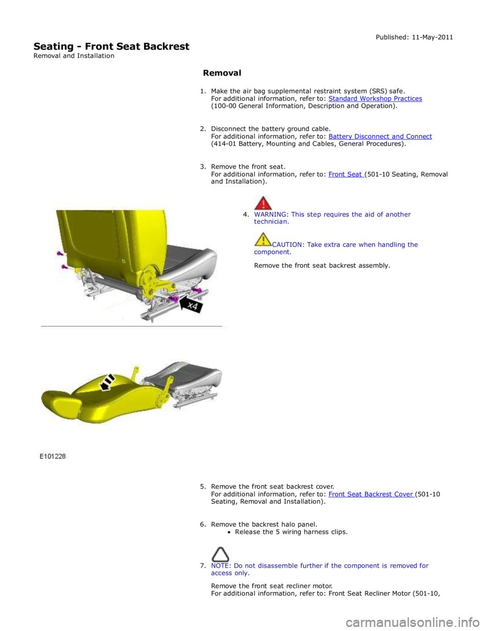
Seating - Front Seat Backrest
Removal and Installation Published: 11-May-2011
Removal
1. Make the air bag supplemental restraint system (SRS) safe.
For additional information, refer to: Standard Workshop Practices (100-00 General Information, Description and Operation).
2. Disconnect the battery ground cable.
For additional information, refer to: Battery Disconnect and Connect (414-01 Battery, Mounting and Cables, General Procedures).
3. Remove the front seat.
For additional information, refer to: Front Seat (501-10 Seating, Removal and Installation).
4. WARNING: This step requires the aid of another
technician.
CAUTION: Take extra care when handling the
component.
Remove the front seat backrest assembly.
5. Remove the front seat backrest cover.
For additional information, refer to: Front Seat Backrest Cover (501-10 Seating, Removal and Installation).
6. Remove the backrest halo panel.
Release the 5 wiring harness clips.
7. NOTE: Do not disassemble further if the component is removed for
access only.
Remove the front seat recliner motor.
For additional information, refer to: Front Seat Recliner Motor (501-10,