engine coolant JAGUAR XJ6 1994 2.G Owner's Manual
[x] Cancel search | Manufacturer: JAGUAR, Model Year: 1994, Model line: XJ6, Model: JAGUAR XJ6 1994 2.GPages: 521, PDF Size: 17.35 MB
Page 98 of 521
Fuel, Emission Control & Engine Management (V12) ~~ ~
5.2.5
SRO
18.30.74 VEHICLE SET
IDLE SPEED CONTROL VALVE/ GASKETS, RENEW
SRO
18.30.73 VALVE- RIGHT HAND
SRO 18.30.76 GASKET
- RIGHT HAND
SRO
SRO 18.30.75 GASKET- LEFT HAND
18.30.72
VALVE
- LEFT HAND
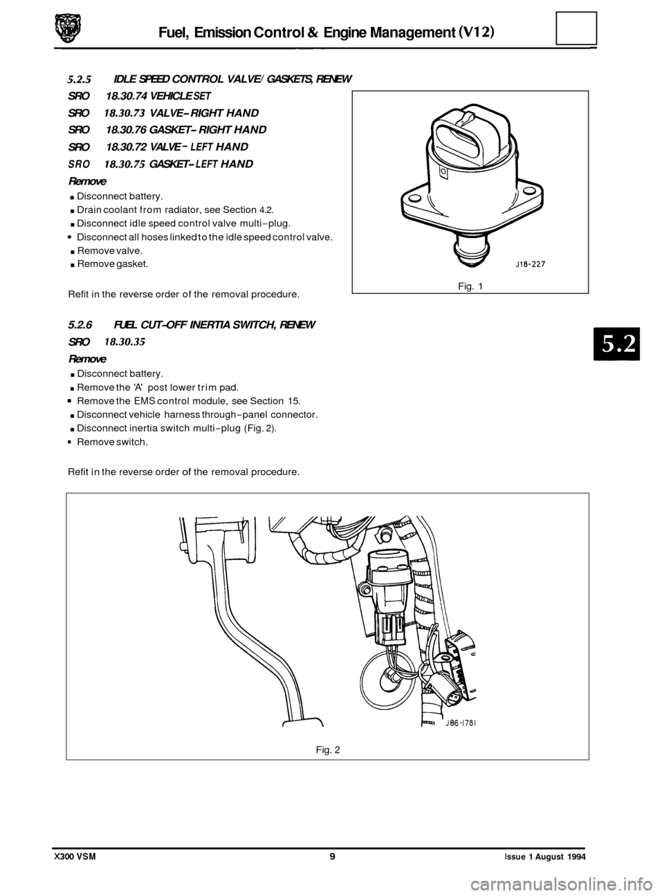
Remove
. Disconnect battery.
. Drain coolant from radiator, see Section 4.2.
. Disconnect idle speed control valve multi-plug.
Disconnect all hoses linked to the idle speed control valve.
. Remove valve.
. Remove gasket.
Refit in the reverse order of the removal procedure.
5.2.6 FUEL CUT-OFF INERTIA SWITCH, RENEW
SRO
18.30.35
Remove
. Disconnect battery.
. Remove the 'A' post lower trim pad.
= Remove the EMS control module, see Section 15.
. Disconnect vehicle harness through-panel connector.
. Disconnect inertia switch multi-plug (Fig. 2).
9 Remove switch.
Refit in the reverse order
of the removal procedure. Fig.
1
Fig. 2
X300 VSM 9 Issue 1 August 1994
Page 201 of 521
@ Steering
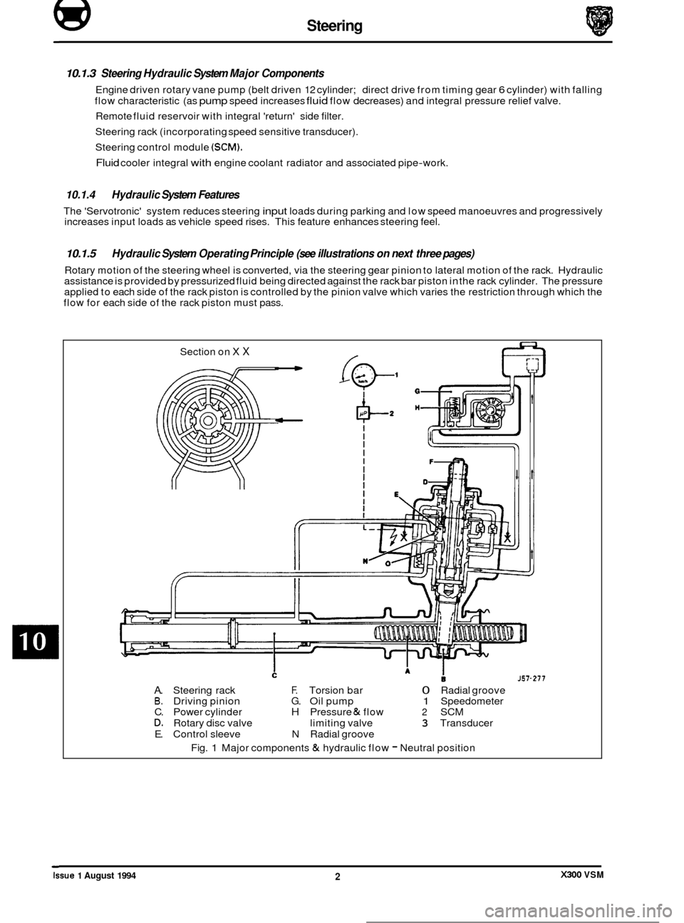
10.1.3 Steering Hydraulic System Major Components
Engine driven rotary vane pump (belt driven 12 cylinder; direct drive from timing gear 6 cylinder) with falling
flow characteristic (as
pump speed increases fluid flow decreases) and integral pressure relief valve.
Remote fluid reservoir with integral 'return' side filter.
Steering rack (incorporating speed sensitive transducer).
Steering control module
(SCM).
Fluid cooler integral with engine coolant radiator and associated pipe-work.
10.1.4 Hydraulic System Features
The 'Servotronic' system reduces steering input loads during parking and low speed manoeuvres and progressively
increases input loads as vehicle speed rises. This feature enhances steering feel.
10.1.5
Rotary motion of the steering wheel is converted, via the steering gear pinion to lateral motion of the rack. Hydraulic
assistance is provided by pressurized fluid being directed against the rack bar piston in the rack cylinder. The pressure
applied to each side of the rack piston is controlled by the pinion valve which varies the restriction through which the
flow for each side of the rack piston must pass.
Hydraulic System Operating Principle (see illustrations on next three pages)
Section on X X
J57-277
A. Steering rack F. Torsion bar 0 Radial groove B. Driving pinion G. Oil pump 1 Speedometer
C. Power cylinder H Pressure & flow 2 SCM D. Rotary disc valve limiting valve 3 Transducer
E. Control sleeve N Radial groove
Fig.
1 Major components & hydraulic flow - Neutral position ~
Issue 1 August 1994 X300 VSM 2
Page 207 of 521
@ Steering
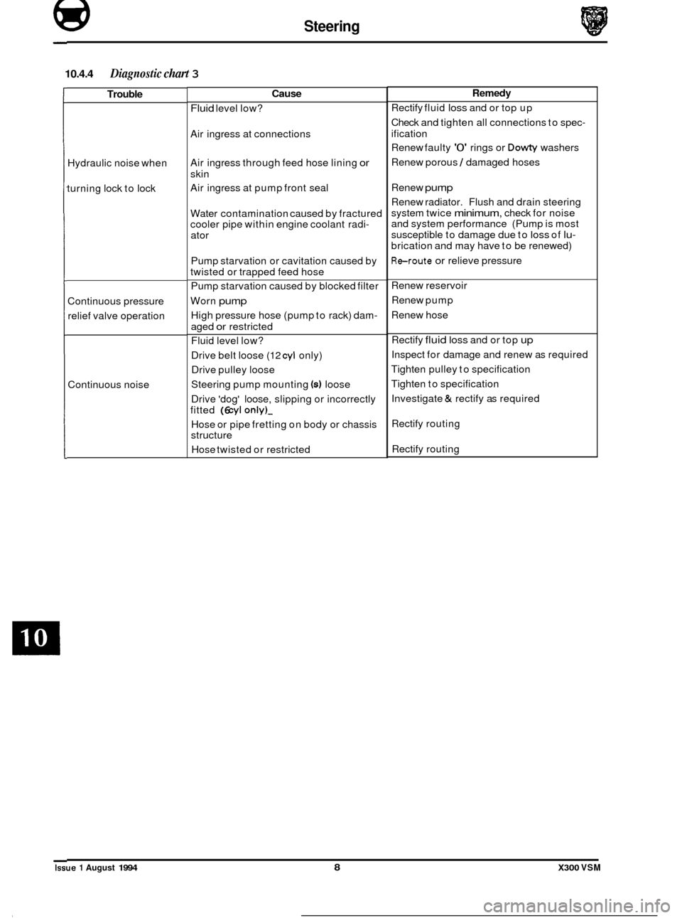
10.4.4 Diagnostic chart 3
Trouble
Hydraulic noise when
turning lock to lock
Continuous pressure
relief valve operation
Continuous noise
Cause
Fluid level low?
Air ingress at connections
Air ingress through feed hose lining
or
skin
Air ingress at pump front seal
Water contamination caused by fractured
cooler pipe within engine coolant radi
-
ator
Pump starvation or cavitation caused by
twisted or trapped feed hose
Pump starvation caused by blocked filter
Worn
pump
High pressure hose (pump to rack) dam-
aged or restricted
Fluid level low?
Drive belt loose
(12 cyl only)
Drive pulley loose
Steering pump mounting
(4 loose
Drive 'dog' loose, slipping or incorrectly
fitted
(6 cyl only)-
Hose or pipe fretting on body or chassis
structure
Hose twisted or restricted
Remedy
Rectify fluid loss and or top up
Check and tighten all connections to spec
-
ification
Renew faulty
'0' rings or Dowty washers
Renew porous
1 damaged hoses
Renew
pump
Renew radiator. Flush and drain steering
system twice
minimum, check for noise
and system performance (Pump is most
susceptible to damage due to
loss of lu-
brication and may have to be renewed)
Reroute or relieve pressure
Renew reservoir
Renew pump
Renew hose
Rectify
fluid loss and or top up
Inspect for damage and renew as required
Tighten pulley to specification
Tighten to specification
Investigate
& rectify as required
Rectify routing
Rectify routing
Issue 1 August 1994 8 X300 VSM
Page 319 of 521
Climate Control Systems
14.4 TEMPERATURE CONTROL
14.4.1 Coolant Circuit
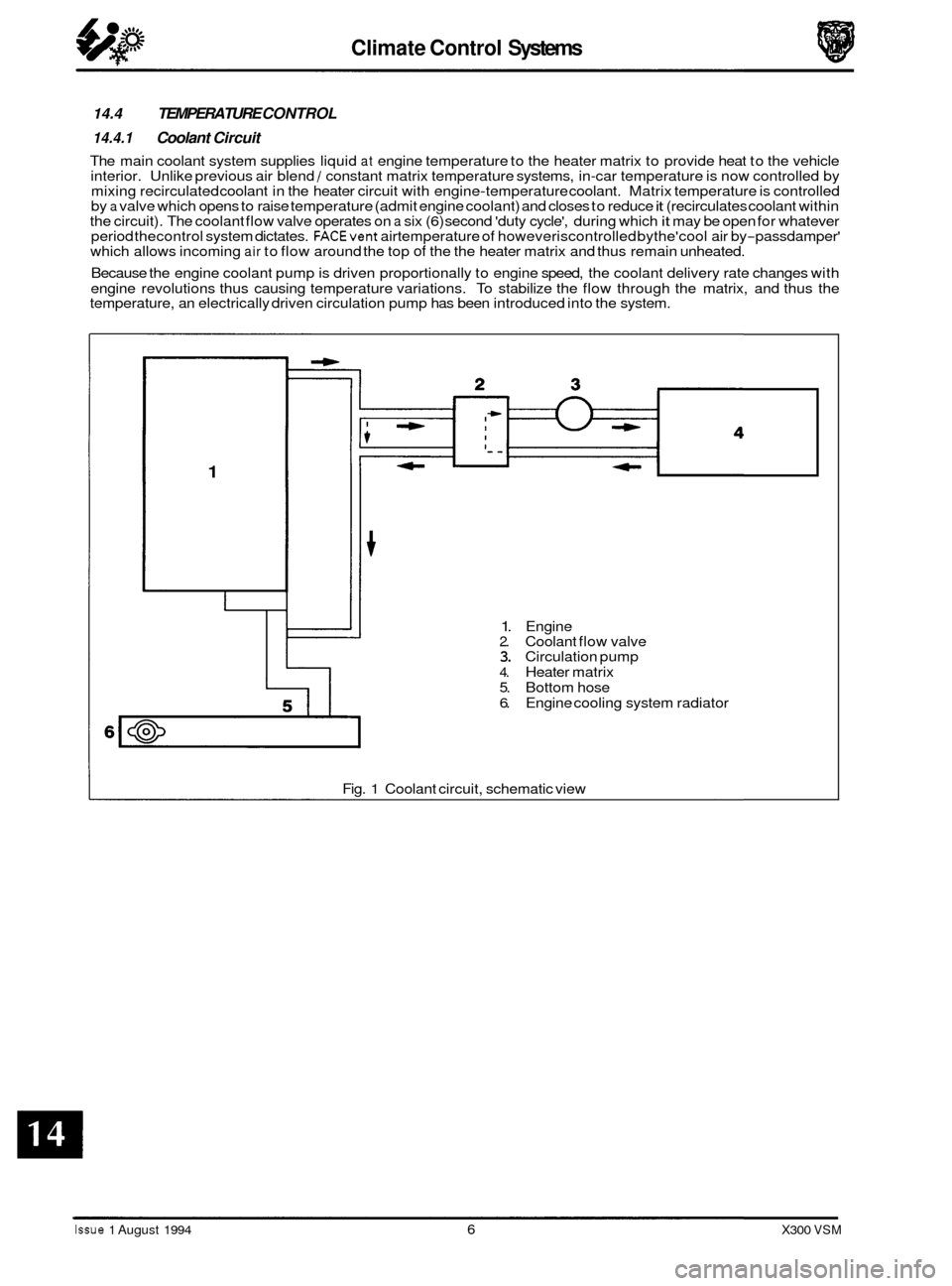
The main coolant system supplies liquid at engine temperature to the heater matrix to provide heat to the vehicle
interior. Unlike previous air blend / constant matrix temperature systems, in-car temperature is now controlled by
mixing recirculated coolant in the heater circuit with engine-temperature coolant. Matrix temperature is controlled
by a valve which opens to raise temperature (admit engine coolant) and closes to reduce it (recirculates coolant within
the circuit). The coolant flow valve operates on a six (6) second 'duty cycle', during which it may be open for whatever
period thecontrol system dictates. FACEvent airtemperature of howeveriscontrolled bythe'cool air by-passdamper'
which allows incoming air to flow around the top of the the heater matrix and thus remain unheated.
Because the engine coolant pump is driven proportionally to engine speed, the coolant delivery rate changes with
engine revolutions thus causing temperature variations. To stabilize the flow through the matrix, and thus the
temperature, an electrically driven circulation pump has been introduced into the system.
1
1. Engine 2. Coolant flow valve 3. Circulation pump
4. Heater matrix
5. Bottom hose
6. Engine cooling system radiator
Fig.
1 Coolant circuit, schematic view
Issue 1 August 1994 6 X300 VSM
Page 320 of 521
Climate Control Systems
Manual Inputs
Automatic inputs
outputs
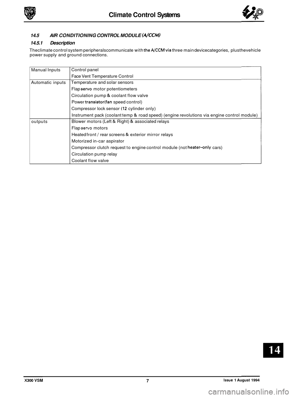
14.5 AIR CONDITIONING CONTROL MODULE (A/CCM)
14.5.1 Description
Theclimate control system peripheralscommunicate with theA/CCMvia three main devicecategories, plusthevehicle
power supply and ground connections.
Control panel Face Vent Temperature Control
Temperature and solar sensors
Flap
servo motor potentiometers
Circulation pump
& coolant flow valve
Power
transistor(fan speed control)
Compressor lock sensor
(12 cylinder only)
Instrument pack (coolant temp
& road speed) (engine revolutions via engine control module)
Blower motors (Left
& Right) & associated relays
Flap
servo motors
Heated front
/ rear screens & exterior mirror relays
Motorized in
-car aspirator
Compressor clutch request to engine control module (not
heater-only cars)
Circulation pump relay
Coolant flow valve
X300 VSM Issue 1 August 1994 7
Page 321 of 521
Climate Control Systems
. Centre vent flap
Foot flap
Defrost flap
I I
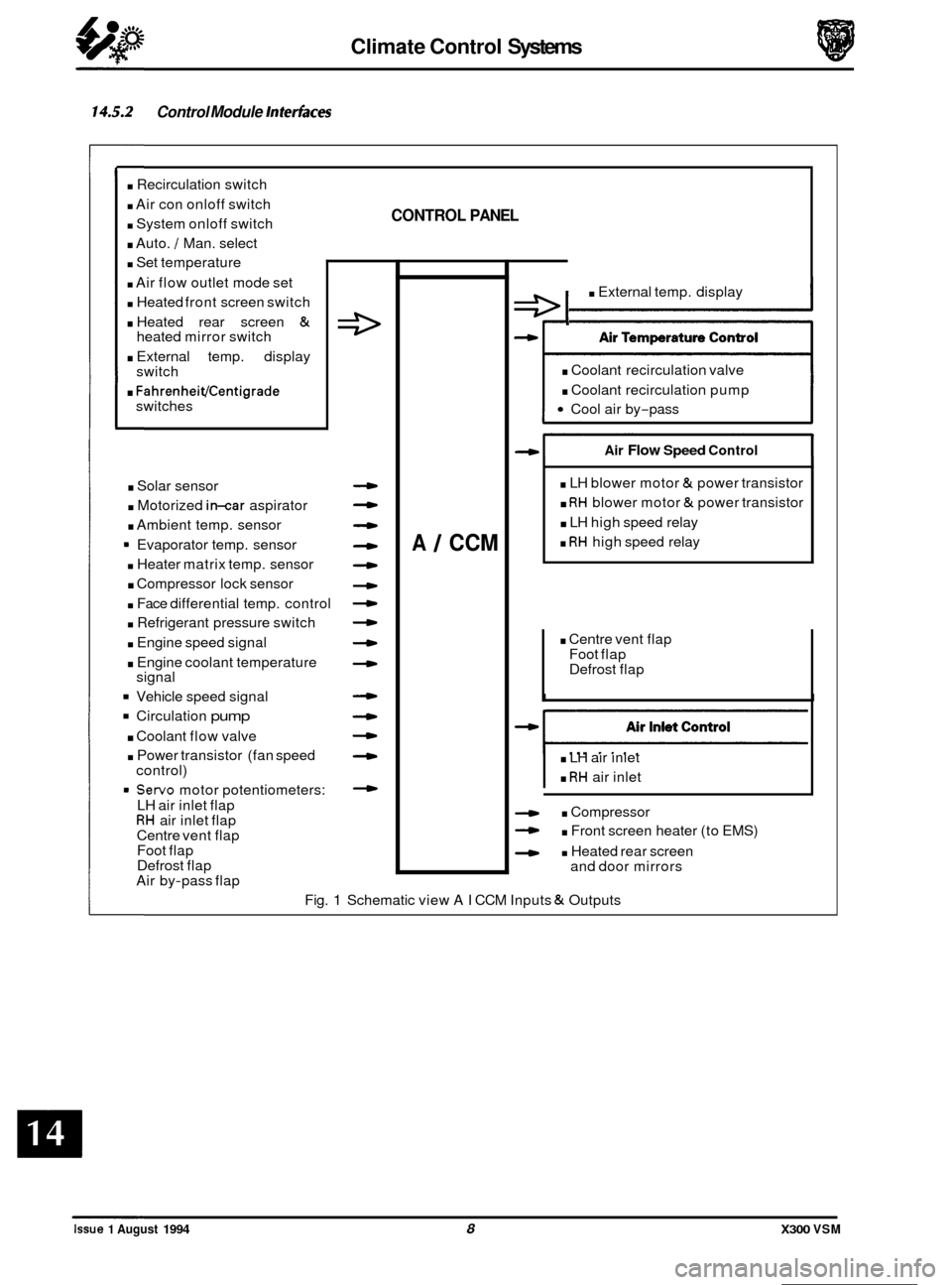
14.5.2 Control Module Interfaces
. Recirculation switch
. Air con onloff switch
. System onloff switch
. Auto. / Man. select
. Set temperature
. Air flow outlet mode set
. Heated front screen switch
. Heated rear screen &
. External temp. display
. FahrenheiVCentigrade
heated mirror switch
switch
switches
. Solar sensor
. Motorized in-car aspirator
. Ambient temp. sensor
9 Evaporator temp. sensor
. Heater matrix temp. sensor
. Compressor lock sensor
. Face differential temp. control
. Refrigerant pressure switch
. Engine speed signal
. Engine coolant temperature
Vehicle speed signal
Circulation pump
. Coolant flow valve
. Power transistor (fan speed
= Servo motor potentiometers:
signal
control)
LH air inlet flap
RH air inlet flap
Centre vent flap
Foot flap
Defrost flap
Air by
-pass flap
CONTROL PANEL
4
-
4
4
4
4
4
4
A 1 CCM
e I . External temp. display
. Coolant recirculation valve
. Coolant recirculation pump
Cool air by-pass
Air Flow Speed Control
. LH blower motor & power transistor
. RH blower motor & power transistor
. LH high speed relay
. RH high speed relay
. LH air inlet
. RH air inlet
. Compressor
- . Front screen heater (to EMS)
- . Heated rear screen
and door mirrors
Fig.
1 Schematic view AI CCM Inputs & Outputs
0
0
0
0
Issue 1 August 1994 8 X300 VSM
Page 322 of 521
Climate Control Systems
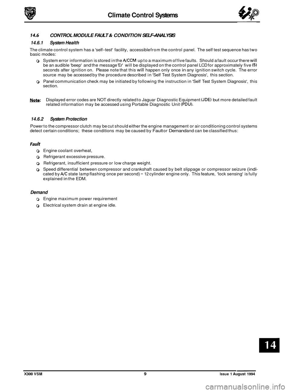
CONTROL MODULE FAULT & CONDITION SELF-ANALYSIS
0 14.6 14.6.1 System Health
The climate control system has a 'self-test' facility, accessible from the control panel. The self test sequence has two
basic modes:
0 System error information is stored in the A/CCM up to a maximum of five faults. Should a fault occur there will
be an audible 'beep' and the message 'Er' will be displayed on the control panel LCD for approximately five (5)
seconds after ignition on. Please note that this will happen only once in any ignition switch cycle. The error
source may be accessed by the procedure described in 'Self Test System Diagnosis', this section.
0 Panel communication check may be initiated by following the instruction in 'Self Test System Diagnosis', this
section.
Nsfe: Displayed error codes are NOT directly related to Jaguar Diagnostic Equipment (JDE) but more detailed fault
related information may be accessed using Portable Diagnostic Unit (PDU).
14.6.2 System Protection
Power to the compressor clutch may be cut should either the engine management or air conditioning control systems
detect certain conditions; these conditions may be caused by Fault or Demand and can be classified thus:
0 Engine coolant overheat,
0 Refrigerant excessive pressure.
0 Refrigerant, insufficient pressure or low charge weight.
0 Speed differential between compressor and crankshaft caused by belt slippage or compressor seizure (indi-
cated by A/C state lamp flashing once per second) - 12 cylinder engine only. This feature, 'lock sensing' is fully
explained
in the EDM.
Demand
0 Engine maximum power requirement
0 Electrical system drain at engine idle.
X300 VSM 9 Issue 1 August 1994
Page 331 of 521
Climate Control Systems
No heat
One vent failing to open
/ close
Poor airflow
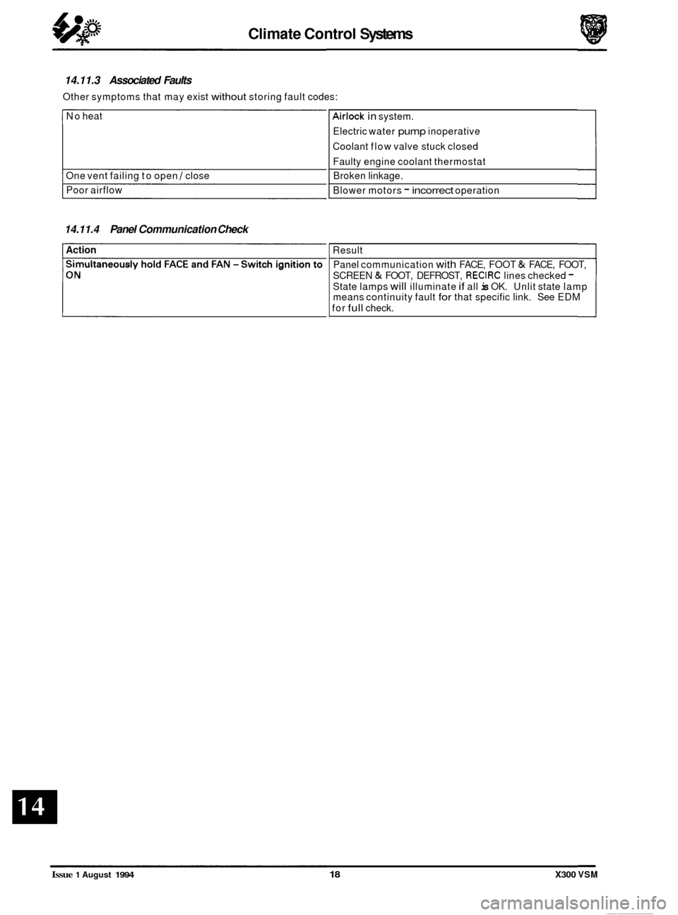
14.11.3 Associated Faults
Other symptoms that may exist without storing fault codes:
Airlock in system.
Electric water
pump inoperative
Coolant flow valve stuck closed
Faulty engine coolant thermostat
Broken linkage.
Blower motors
- incorrect operation
14.11.4 Panel Communication Check
Action Result
Panel communication
with FACE, FOOT & FACE, FOOT,
SCREEN
& FOOT, DEFROST, RECIRC lines checked - State lamps will illuminate if all is OK. Unlit state lamp
means continuity fault for that specific link. See EDM
for
full check.
0
0
0
Issue 1 August 1994 18 X300 VSM
Page 349 of 521
Electrical rl
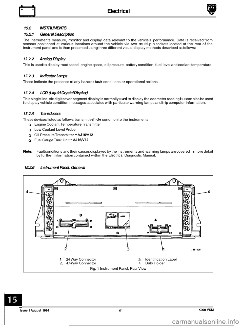
15.2 INSTRUMENTS
15.2.1 General Description
The instruments measure, monitor and display data relevant to the vehicle’s performance. Data is received from
sensors positioned at various locations around the vehicle via two multi-pin sockets located at the rear of the
instrument panel and is than presented using three different visual display methods described as follows:
15.2.2 Analog Display
This is used to display road speed, engine speed, oil pressure, battery condition, fuel level and coolant temperature.
15.2.3 Indicator Lamps
These indicate the presence of any hazard /fault conditions or operational actions.
15.2.4 LCD (Liquid Crystal Disp/ay)
This single line, six digit seven segment display is normally used to display the odometer reading but can also be used
to display vehicle condition messages associated with particular warning lamps and trip computer information.
15.2.5 Transducers
These devices listed as follows transmit vehicle condition to the instruments:
0 Engine Coolant Temperature Transmitter
0 Low Coolant Level Probe
0 Oil Pressure Transmitter - AJ16N12
0 Fuel Gauge Tank Unit - AJlW12
Fault conditions and their causes displayed by the instruments and warning lamps are covered in more detail
by further information contained within the
Electrical Diagnostic Manual.
15.2.6 Instrument Panel, General
2 I I 3 1
1. 24 Way Connector 3. Identification Label 2. 4% Way Connector 4. Bulb Holder
Fig.
1 Instrument Panel, Rear View
X300 VSM Issue 1 August 1994 8
c
Page 350 of 521
31
30
29
28 27
26
4 26 24 21 23 22 7 20 19 18 18 17 8
a
10
11
12
13
14
1s
1M-137
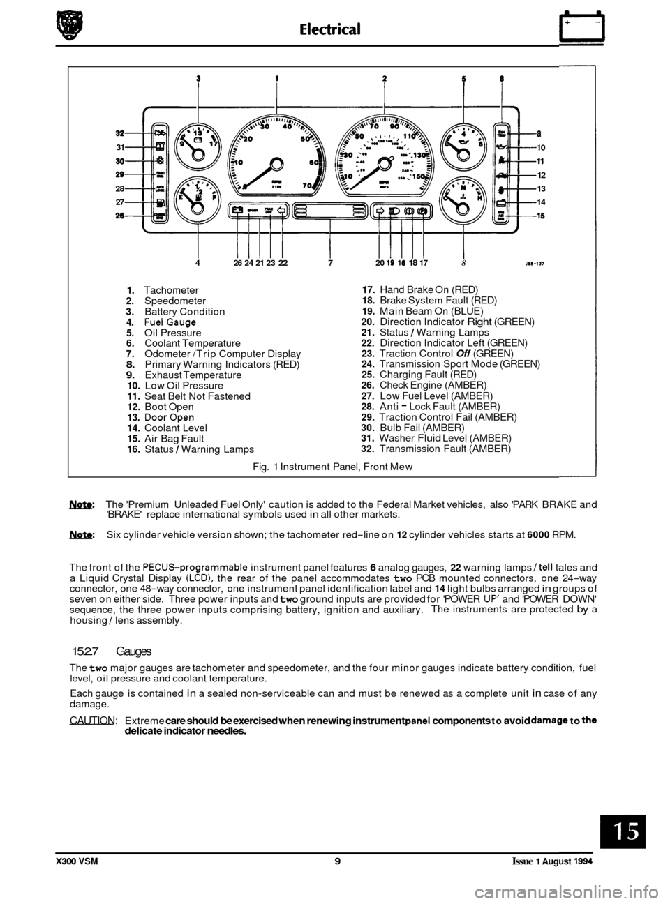
1. Tachometer 2. Speedometer
3. Battery Condition 4. FuelGauge 5. Oil Pressure 6. Coolant Temperature 7. Odometer /Trip Computer Display 8. Primary Warning Indicators (RED) 9. Exhaust Temperature 10. Low Oil Pressure 11. Seat Belt Not Fastened 12. Boot Open 13. DoorOpen 14. Coolant Level 15. Air Bag Fault 16. Status / Warning Lamps
17. Hand Brake On (RED) 18. Brake System Fault (RED)
19. Main Beam On (BLUE) 20. Direction Indicator Right (GREEN) 21. Status / Warning Lamps 22. Direction Indicator Left (GREEN) 23. Traction Control Off (GREEN) 24. Transmission Sport Mode (GREEN) 25. Charging Fault (RED) 26. Check Engine (AMBER)
27. Low Fuel Level (AMBER) 28. Anti - Lock Fault (AMBER) 29. Traction Control Fail (AMBER) 30. Bulb Fail (AMBER) 31. Washer Fluid Level (AMBER) 32. Transmission Fault (AMBER)
Fig.
1 Instrument Panel, Front Mew
w: The 'Premium Unleaded Fuel Only' caution is added to the Federal Market vehicles, also 'PARK BRAKE and
'BRAKE' replace international symbols used in all other markets.
m: Six cylinder vehicle version shown; the tachometer red-line on 12 cylinder vehicles starts at 6000 RPM.
The front of the
PECUSprogrammable instrument panel features 6 analog gauges, 22 warning lamps /tell tales and
a Liquid Crystal Display (LCD), the rear of the panel accommodates two PCB mounted connectors, one 24-way
connector, one 48-way connector, one instrument panel identification label and 14 light bulbs arranged in groups of
seven on either side. Three power inputs and two ground inputs are provided for 'POWER UP' and 'POWER DOWN'
sequence, the three power inputs comprising battery, ignition and auxiliary. The instruments are protected by a
housing
/ lens assembly.
15.2.7 Gauges
The two major gauges are tachometer and speedometer, and the four minor gauges indicate battery condition, fuel
level, oil pressure and coolant temperature.
Each gauge is contained
in a sealed non-serviceable can and must be renewed as a complete unit in case of any
damage.
CAUTION: Extreme care should be exercised when renewing instrument pand components to avoid damago to the delicate indicator needles.
X300 VSM 9 Issue 1 August 1994