key JAGUAR XJ6 1994 2.G Owner's Manual
[x] Cancel search | Manufacturer: JAGUAR, Model Year: 1994, Model line: XJ6, Model: JAGUAR XJ6 1994 2.GPages: 521, PDF Size: 17.35 MB
Page 400 of 521
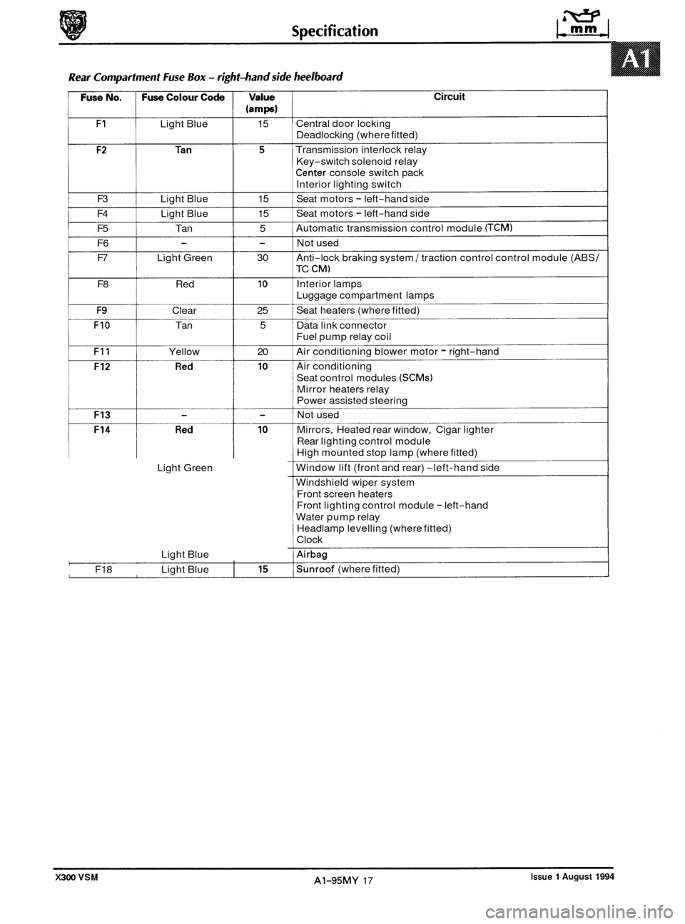
(amps)
F1 Light Blue 15
F3 Light Blue 15
F4 Light Blue 15
F5 Tan 5
F6 F7 Light Green 30
- -
F8 Red 10
F9 Clear 25
FIO Tan 5
F11 Yellow 20 0
Light Green
Light Blue
F18 Light Blue
0'
I
Circuit
Central door locking
Deadlocking (where fitted)
Transmission interlock relay
Key
-switch solenoid relay
Center console switch pack
Interior lighting switch
Seat motors
- left-hand side
Seat motors
- left-hand side
Automatic transmission control module
(TCM)
Not used
Anti
-lock braking system / traction control control module (ABS /
TC CM)
Interior lamps
Luggage compartment lamps
Seat heaters (where fitted)
Data link connector
Fuel pump relay coil
Air conditioning blower motor
- right-hand
Air conditioning
Seat control modules
(SCMs)
Mirror heaters relay
Power assisted steering
Not used
Mirrors, Heated rear window, Cigar lighter
Rear lighting control module
High mounted stop lamp (where fitted)
Window lift (front and rear)
-left-hand side
Windshield wiper system Front screen heaters
Front lighting control module
- left-hand
Water pump relay
Headlamp levelling (where fitted)
Clock
Airbag
Sunroof (where fitted)
Issue 1 August 1994 AI-95MY 17 X300 VSM
Page 410 of 521
General Fitting Instructions
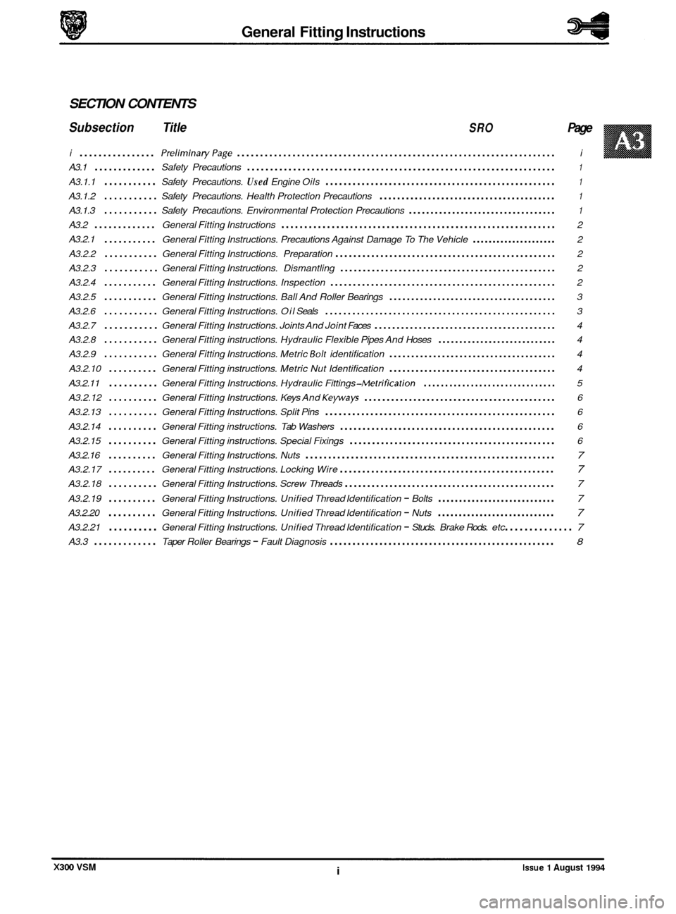
SECTION CONTENTS
Subsection Title SRO Page
i ................ PreliminaryPage ..................................................................... i
A3.1 ............. Safety Precautions ................................................................... 1
A3.1.1 ........... Safety Precautions. Used Engine Oils ................................................... 1
A3.1.2 ........... Safety Precautions. Health Protection Precautions ........................................ 1
A3.1.3 ........... Safety Precautions. Environmental Protection Precautions .................................. 1
A3.2 ............. General Fitting Instructions ............................................................ 2
A3.2.1
........... General Fitting Instructions. Precautions Against Damage To The Vehicle ..................... 2
A3.2.2
........... General Fitting Instructions. Preparation ................................................. 2
A3.2.3
........... General Fitting Instructions. Dismantling ................................................ 2
A3.2.4
........... General Fitting Instructions. Inspection .................................................. 2
A3.2.5
........... General Fitting Instructions. Ball And Roller Bearings ...................................... 3
A3.2.6
........... General Fitting Instructions. Oil Seals ................................................... 3
A3.2.7
........... General Fitting Instructions. Joints And Joint Faces ......................................... 4
A3.2.8
........... General Fitting instructions. Hydraulic Flexible Pipes And Hoses ............................ 4
A3.2.9
........... General Fitting Instructions. Metric Bolt identification ...................................... 4
A3.2.10
.......... General Fitting instructions. Metric Nut Identification ...................................... 4
A3.2.11
.......... General Fitting Instructions. Hydraulic Fittings -Metrification ............................... 5
A3.2.12
.......... General Fitting Instructions. Keys And Keyways ........................................... 6
A3.2.13
.......... General Fitting Instructions. Split Pins ................................................... 6
A3.2.14
.......... General Fitting instructions. Tab Washers ................................................ 6
A3.2.15
.......... General Fitting instructions. Special Fixings .............................................. 6
A3.2.16
.......... General Fitting Instructions. Nuts ....................................................... 7
A3.2.17 .......... General Fitting Instructions. Locking Wire ................................................ 7
A3.2.18 .......... General Fitting Instructions. Screw Threads ............................................... 7
A3.2.19 .......... General Fitting Instructions. Unified Thread Identification - Bolts ............................ 7
A3.2.20 .......... General Fitting Instructions. Unified Thread Identification - Nuts ............................ 7
A3.2.21 .......... General Fitting Instructions. Unified Thread Identification - Studs. Brake Rods. etc .............. 7
A3.3 ............. Taper Roller Bearings - Fault Diagnosis .................................................. 8
X300 VSM i Issue 1 August 1994
Page 417 of 521
General Fitting Instructions
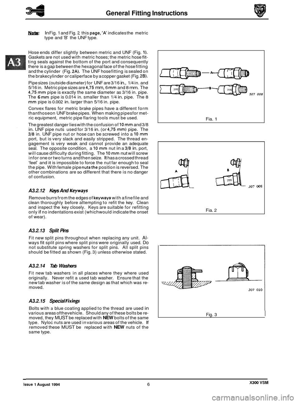
In Fig. 1 and Fig. 2, this page,’K indicates the metric
type and ’B’ the UNF type.
Hose ends differ slightly between metric and UNF (Fig.
1). Gaskets are not used with metric hoses; the metric hose fit- ting seals against the bottom of the port and consequently
there is a gap between the hexagonal face of the hose fitting
and the cylinder (Fig.
2A). The UNF hose fitting is sealed on
the brakecylinder or caliperface by a copper gasket (Fig.
2B).
Pipe sizes (outside diameter) for UNF are 3/16 in., 1/4 in. and
5/16 in. Metric pipe sizes are 4,75 mm, 6 mm and 8 mm. The 4,75 mm pipe is exactly the same diameter as 3/16 in. pipe.
The 6 mm pipe is 0.014 in. smaller than 1/4 in. pipe. The 8
mm pipe is 0.002 in. larger than 5/16 in. pipe.
Convex flares for metric brake pipes have a different form
thanthoseon UNF brake pipes. When making pipesfor met
- ric equipment, metric pipe flaring tools must be used.
The greatest danger lies with the confusion of
10 mm and 3/8 in. UNF pipe nuts used for 3/16 in. (or 4,75 mm) pipe. The 318 in. UNF pipe nut or hose can be screwed into a 10 mm port, but is very slack and easily stripped. The thread en- gagement is very weak and cannot provide an adequate
seal. The opposite condition, a 10 mm nut in a 318 in. port,
will cause difficulty during fitting. The
10 mm nut will screw
in for one or two turns and then seize. It has a crossed thread
‘feel’ and
it is impossible to force the nut far enough to seal
the pipe. With female pipe nutsthe position is reversed. The
other combinations are so different that there is no danger
of confusion.
A3.2.12 Keys And Keyways
Remove burrs from the edges of keyways with a fine file and
clean thoroughly before attempting to refit the key. Clean
and inspect the key closely. Keys are suitable for refitting
only
if no indentations exist (which would indicate the onset
of wear).
A3.2.13 Split Pins
Fit new split pins throughout when replacing any unit. Al- ways fit split pins where split pins were originally used. Do not substitute spring washers for split pins. All split pins
should be fitted as shown (Fig. 3) unless otherwise stated.
A3.2.14 Tab Washers
Fit new tab washers in all places where they where used
originally. Never refit a used tab washer. Ensure that the
new tab washer is of the same design as that which was re
- moved.
A3.2.15 Special Fixing
Bolts with a blue coating applied to the thread are used in various areas ofthevehicle. Should any of these bolts be re- moved, they MUST be replaced with NEW bolts of the same
type. Nyloc nuts are used in various areas of the vehicle. If removed these MUST be replaced with NEW nuts of the
same type.
-A
507 008
Fia. 1
Fia. 2
Fig. 3 I
X300 VSM Issue 1 August 1994 6
Page 424 of 521
SECTION CON TENTS
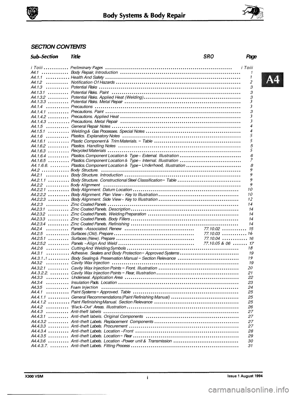
Suh-Section Title SRO Page
i Toiii ............ PreliminaryPages ................................................................ i Toiii
A4.1
............. Body Repair, Introduction ............................................................. 1
A4.1.1 ........... Health And Safety .................................................................... 1
A4.1.2 ........... Notification Of Hazards ............................................................... 2
A4.1.3 ........... Potential Risks ....................................................................... \
3
A4.1.3.1
.......... Potential Risks. Paint ................................................................. 3
A4.1.3.2
.......... Potential Risks. Applied Heat (Welding) .................................................. 3
A4.1.3.3 .......... Potential Risks. Metal Repair ........................................................... 3
A4.1.4 ........... Precautions ........................................................................\
. 3
A4.1.4.1 ..........
A4.1.4.2 ..........
A4.1.4.3 ..........
A4.1.5 ...........
A4.1.5.1 ..........
A4.1.6 ...........
A4.1.6.1 ..........
A4.1.6.2 ..........
A4.1.6.3 ..........
A4.1.6.4 ..........
A4.1.6.5 ..........
A4.1.6.6. .........
Precautions. Paint .................................................................... 3
Precautions. Applied Heat
............................................................. 3
Precautions. Metal Repair ............................................................. 3
General Repair Notes ................................................................. 4
Welding & Gas Processes. Special Notes ................................................. 4
Plastic Component & Trim Materials. - Table ............................................. 5
Plastics. Explanatory Notes ............................................................ 5
Plastics. Handling Notes .............................................................. 5
Recycled Materials
................................................................... 5
Plastics. Component Location & Type - External. Illustration ................................. 6
Plastics. Component Location
& Type - Internal. Illustration ................................. 7
Plastics. Component Location & Type - Underhood. Illustration .............................. 8
A4.2 ............. Body Structure. ...................................................................... 9
A4.2.1 ........... Body Structure. Introduction ........................................................... 9
A4.2.2.1 .......... Body Alignment. Datum Location ...................................................... 10
A4.2.2.2 .......... Body Alignment. Plan View - Key to Illustration .......................................... 10
A4.2.2.3 .......... Body Alignment. Side View - Key to Illustration .......................................... 12
A4.2.3 ........... Zinc Coated Panels .................................................................. 14
A4.2.3.1 .......... Zinc Coated Panels. Description ....................................................... 14
A4.2.3.2
.......... Zinc Coated Panels. Welding Preparation ............................................... 14
A4.2.3.3
.......... Zinc Coated Panels. Body Fillers ....................................................... 14
A4.2.3.4
.......... Zinc Coated Panels. Refinishing ....................................................... 14
A4.2.4
........... Panels -Associated. Renew ..................................... 77.10.02 ............ 15
A4.2.5
........... Surfaces (Old). Prepare .......................................... 77.10.03 ............ 16
A4.2.5.1 .......... Surfaces (New). Prepare ......................................... 77.10.04 ............ 16
A4.2.5.2 .......... Panels -Align And Weld ........................................ 77.10.05 & 06 ....... 17
A4.2.6 ........... Cutting And Welding Symbols ......................................................... 18
A4.3.1 ........... Adhesive. Sealers and Body Protection - Approved Systems ................................ 19
A4.3.
1 . 1 .......... Body Sealing & Preservation Manual - Section Relevance ................................. 19 A4.3.2 ........... Cavity Wax Injection ................................................................ 19
A4.3.2.1
.......... Cavity Wax Injection Points - Front. Illustration .......................................... 20
A4.3.2.2. ......... Cavity Wax Injection Points - Rear, Illustration ........................................... 21
A4.3.3 ........... Underseal. Application Area .......................................................... 22
A4.3.4
........... Insulation Pads. Location ............................................................. 23
A4.3.5
........... Foamlnjection ..................................................................... 24
A4.4.1 ........... Paint Systems - Approved. Table ...................................................... 25
A4.4.1.1
.......... General Recommendations (Paint Refinishing Manual) .................................... 25
A4.4.1.2
.......... Paint Refinishing Manual. Section Relevance ............................................ 25
A4.4.2
........... ‘Black-Out’ Areas. Illustration ......................................................... 26
A4.4.3 ........... Anti-theft labels .................................................................... 27
A4.4.3.1
.......... Anti-theft labels. Original Components ................................................ 27
A4.4.3.2
.......... Anti-theft Labels. Replacement Components ............................................ 27
A4.4.3.3 .......... Anti-theft Labels. Procurement ........................................................ 27
A4.4.3.4
.......... Anti-theft Labels. Location -Front ..................................................... 28
A4.4.3.5
.......... Anti-theft Labels. Location - Rear ...................................................... 29
A4.4.3.7.
......... Anti-theft Labels. Fitting Process ....................................................... 31
A4.2.1.1
.......... Body Structure.
Constructional Steel Classification - Table .................................. 9
A4.2.2 ........... BodyAlignment ..................................................................... 9
A4.4.3.6 .......... Anti-theft Labels. Location -Power unit & Transmission ................................... 30
Page 437 of 521

Body Systems & Body Repair
Location
Centre line of the front crossmember rear mounting, at the
main floor
RH longitudinal
A4.2.2.1 Datum location, Example
The FRONT MASTER DATUM (front crossmember rear mounting at the inner face ofthe main floor RH longitudi- nal) is nominally 359,5mm to the right-hand side of the body center line. The LH side front datum is measured 717,0/ 721,Omm from the RH. Please refer to the illustration on the following page.
Expressed as
a true position in three planes, the front master datum is:
Position
X 300,O
Y 359.5 Z -50.0
0
Datum
Front Master Datum
Plan
A4.2.2.2 Key, Plan View
Please refer to the illustration on the opposite page.
Key Location
1
2
3
4
5 Driveshaft centre bearing fixings
6
7
8
9
10 Front
face body
- bumper strut / mounting point
Rearmost hole, Vee
-mount to crush tube
Front Master Datum Plan, centre line
of the front crossmember rear mounting at the main floor RH longi-
tudinal
Rearmost hole, transmission mounting
at the main floor RH longitudinal
Rear Master Datum Plan, rear longitudinal
Tapped boss, rear suspension
'A' frame mounting bush
Rear suspension spring
-pan damper mounting
Rear suspension differential strut mounting
Rear face body
- bumper strut / mounting point
X300 VSM Issue 1 August 1994 10
Page 439 of 521

E 12
Rear face bodv - bumDer strut / mountina Doint
Body Systems
I
& Body
side vww
the illustration on the opposite page.
Repair
Location
Front face body - bumper strut / mounting point
Front Master Datum Vertical. centre line of the front crossmember rear mountina
Front
face body - bumper strut / mounting point
Front Master Datum Vertical, centre line of the front crossmember rear mounting
Transmission mountings
at the main floor longitudinal
Driveshaft centre bearing fixings
Rear Master Datum
Vertical, rear longitudinal
Tapped boss, rear suspension
'A' frame mounting bush
Rear suspension spring
-pan damper mounting
Rear suspension differential strut mounting
Rear face body
- bumper strut / mounting point
Transmission
mountings
at the main floor longitudinal
Driveshaft centre bearing fixings
Rear Master Datum
Vertical, rear longitudinal
Tapped boss, rear suspension
'A' frame mounting bush
Rear suspension spring
-pan damper mounting
Rear
susoension differential strut mounting
Wheel centre to
bummr cover face I
Wheel base I
Wheel centre to bumper cover face
Body Systems & Body Repair
A4.2.2.3 Key, Side Vww
Please refer to the illustration on the opposite page.
0
0
0
X300 VSM Issue 1 August 1994 12
Page 445 of 521
Body Systems & Body Repair
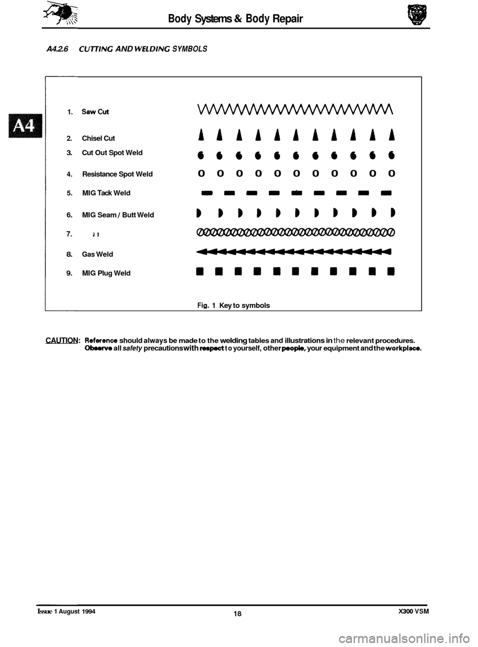
A4.2.6 CU77/NG AND WELDlNG SYMBOLS
1. SawCut
2. Chisel Cut AkAAAkAAkAA
666666@6646
4. Resistance Spot Weld 00000000000
3. Cut Out Spot Weld
5. MIG Tack Weld DmmDmm=m=
6. MIG Seam / Butt Weld BBBBBBBBBBB
7. Braze
8. Gas Weld
9. MIG Plug Weld WIIBIIBBIII
Fig. 1 Key to symbols
CAUTION: Reference should always be made to the welding tables and illustrations in the relevant procedures. Obsenfo all safety precautions with respect to yourself, other peopIe, your equipment and the workplace.
0
0
X300 VSM 18 Issue 1 August 1994
Page 477 of 521
page e
Sub-Section Title SRO
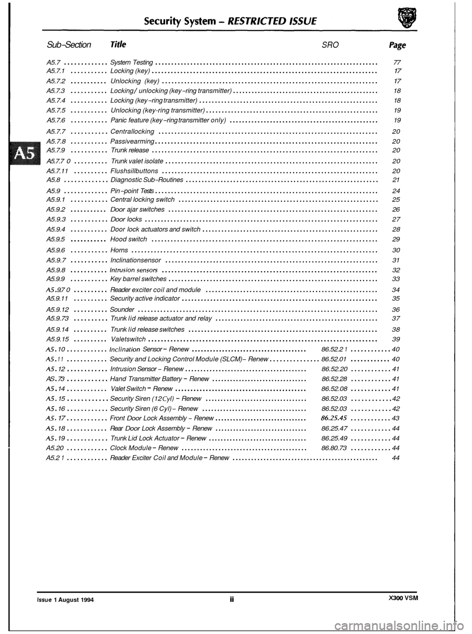
A5.7 ............. System Testing ...................................................................... 77
A5.7.1
........... Locking (key) ....................................................................... \
17
A5.7.2 ........... Unlocking (key) .................................................................... 17
A5.7.3 ........... Locking / unlocking (key-ring transmitter) ............................................... 18
A5.7.4
........... Locking (key-ring transmitter) ......................................................... 18
A5.7.5
........... Unlocking (key-ring transmitter) ....................................................... 19
A5.7.6
........... Panic feature (key-ring transmitter only) ................................................ 19
A5.7.7
........... Centrallocking ..................................................................... 20
A5.7.8
........... Passivearming ...................................................................... 20
A5.7.9
........... Trunk release ....................................................................... \
20
A5.7.7
0 .......... Trunk valet isolate ................................................................... 20
A5.7.11
.......... Flushsillbuttons .................................................................... 20
A5.9
............. Pin-point Tests ...................................................................... 24
A5.8
............. Diagnostic
Sub-Routines ............................................................. 21
A5.9.1
........... Central locking switch ............................................................... 25
A5.9.2
........... Door ajar switches .................................................................. 26
A5.9.3
........... Door locks ........................................................................\
. 27
A5.9.4
........... Door lock actuators and switch ........................................................ 28
A5.9.5
........... Hood switch ....................................................................... \
29 e
A5.9.6 ........... Horns ........................................................................\
..... 30
A5.9.7
........... Inclinationsensor ................................................................... 31
A5.9.8
........... Intrusionsensors .................................................................... 32
A5 . 9.7 0 .......... Reader exciter coil and module ....................................................... 34
A5.9.12
.......... Sounder ........................................................................\
... 36
A5.9.14
.......... Trunk lid release switches ............................................................ 38
A5.9.15
.......... Valetswitch ........................................................................\
39
A5 . 10 ............ Inclination Sensor - Renew ...................................... 86.52.2 1 ............ 40
A5 . 12 ............ Intrusion Sensor - Renew ........................................ 86.52.20 ............ 41
A5 . 14 ............ Valet Switch - Renew ........................................... 86.52.08 ............ 41
A5.9.9
........... Key
barrel switches .................................................................. 33
A5.9.11
.......... Security active indicator .............................................................. 35
A5.9.73
.......... Trunk lid release actuator and relay .................................................... 37
A5 . 11 ............ Security and Locking Control Module (SLCM) - Renew ............... 86.52.01 ............ 40
AS
. 73 ............ Hand Transmitter Battery - Renew ................................ 86.52.28 ............ 41
A5 . 15 ............ Security Siren (12 Cyl) - Renew .................................. 86.52.03 ............ 42
A5 . 16 ............ Security Siren (6 Cyl) - Renew ................................... 86.52.03 ............ 42
A5 . 17 ............ Front Door Lock Assembly - Renew ............................... 86.25.45 ............ 43
A5 . 18 ............ Rear Door Lock Assembly - Renew ............................... 86.25.47 ............ 44
Trunk Lid Lock Actuator - Renew ................................. 86.25.49 ............ 44
Clock Module - Renew ......................................... 86.80.73 ............ 44
Reader Exciter Coil and Module - Renew ............................................... 44
e
A5 . 19 ............
A5.20 ............
A5.2 1 ............
e
X300 VSM Issue 1 August 1994 ii
Page 478 of 521
0
c
doors, windows, trunk, hood and sliding roof.
I Method I UK / EUROPE
of IXJ16I1SOVIIDAIM
Operation Sport XJ12 /DD6
Locking
Central locking Key X X X
Remote central locking Remote X X X
Deadlocking Remote/ X X X
Two stage unlock Remote/
- - - Key
Key
Drive away locks Auto X/DD X/DD X/DD
Switch
close
Interior trunk lid release Switch
Flush
sill buttons /
intrusion override
security
Security system (base)
Intrusion sensing (full)
Inclination sensing
Passive arming
Panic alarm
Audible tones (error
/
deadlock)
Engine immobilization
*
Auto
.,,,
Remote
Auto
1 XI X X
X D
D D
X/ DD
X
-~~
Security System - RESTRICTED ISSUE
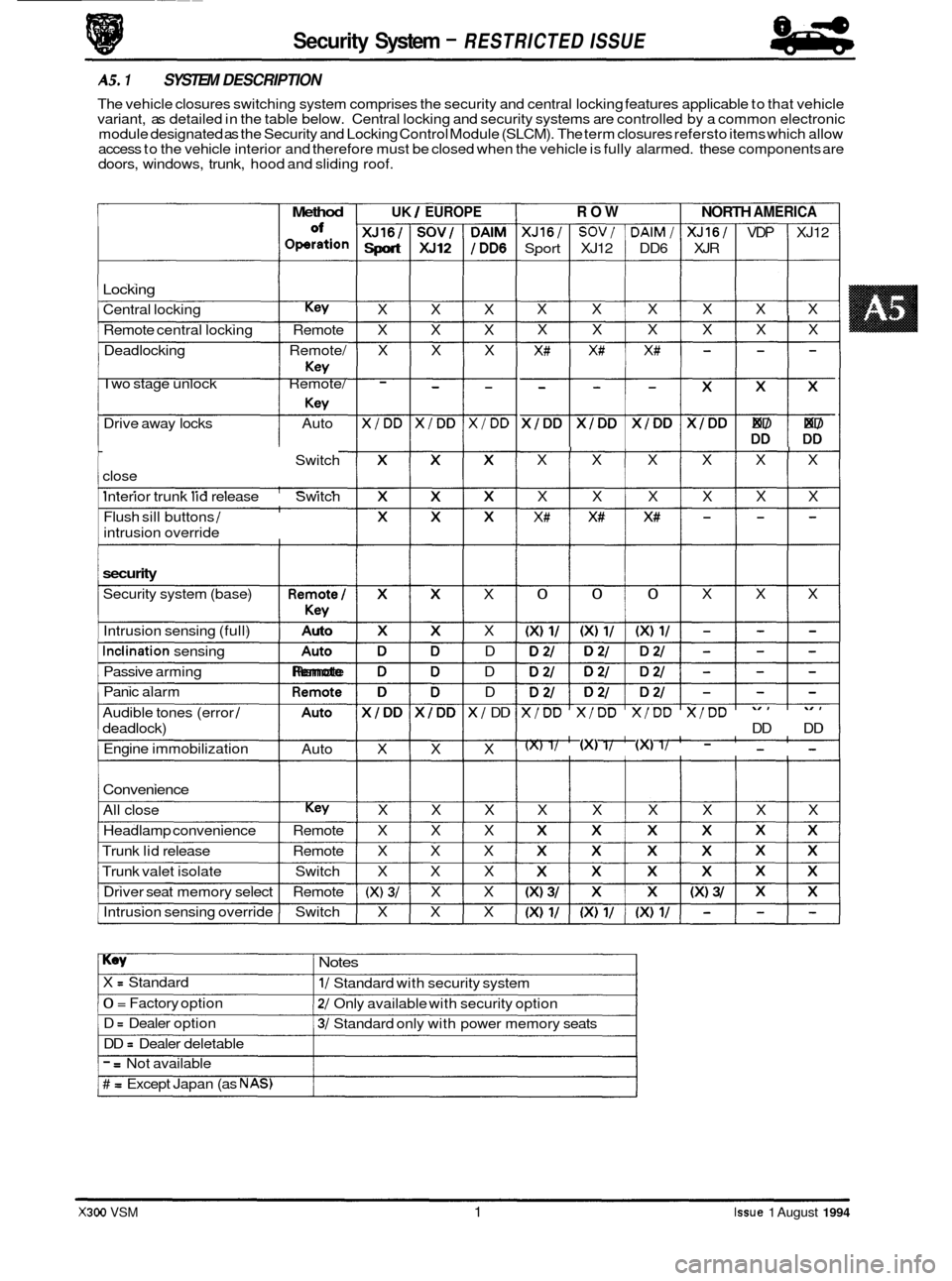
AS. 1 SYSTEM DESCRIPTION
The vehicle closures switching system comprises the security and central locking features applicable to that vehicle
variant, as detailed in the table below. Central locking and security systems are controlled by a common electronic
module designated as the Security and Locking Control Module (SLCM). The term closures refersto items which allow
access to the vehicle interior and therefore must be closed when the vehicle is fully alarmed. these components are
Convenience
All close Key X X X
Headlamp convenience Remote X X X
Trunk lid release Remote X X X
Trunk valet isolate Switch X X X
Driver seat memory select Remote
(X) 3/ X X
Intrusion sensing override Switch X X X
ROW NORTH AMERICA
XJ16/ SOV/ DAlM/ XJ16/ VDP XJ12
Sport XJ12 DD6 XJR
X X X X X X
I X X X X X X
X# X# X# - - -
$$$$$ DD DD
I I I I I X X X X X X
X X X X X X
X# X# X# - - -
I 0 0 0 X X X
X/DD X/DD X/DD X/DD
DD DD
(X) 1/ (XI 1/ (XI 1/ - - -
X X X X X X
Key Notes
X = Standard
0 = Factory option
D
= Dealer option
DD
= Dealer deletable
1/ Standard with security system
2/ Only available with security option
3/ Standard only with power memory seats
- = Not available
# = Except Japan (as NAS)
X300 VSM 1 Issue 1 August 1994
Page 480 of 521
I 03 I Door lock actuators (4 off) 1 part of door assemblv I I
Issue 1 August 1994 X300 VSM 3 I
1 04 I Door lock switches (2 off) I part of door latch assembly I I
1 05 IHoodswitch 1 located above siren I I
1 06 IHorn 1 located on front RH side of en(
1 07 I Inclination sensor I behind luggage compartment LH liner I I
I 08 I Intrusion sensor (LH) I located above LH door behind roof lining I
I 09 I intrusion sensor (RH) 1 located above LH door behind roof lining I
I
1 1 part of door latch assembly I 10 I Key barrel switches (2 off)
1 11 I Key fob transmitter 1 part of key fob I I
I 12 I Key transponder 1 part of key I I
I 13 I Reader exciter coil 1 part of ignition switch I I
I 14 I Reader exciter module 1 part of steering column assembly I I
1 15 I Relays (deadlock) I I I
1 18 I Security active indicator part of central locking switch I I
I 19 I Securitv and lockina control module (SLCM) located in luaaaae compartment behind LH liner I I
1 20 ISounder , located on front RH side of engine bay I I
1 25 IValet switch 1 in centre console compartment I I
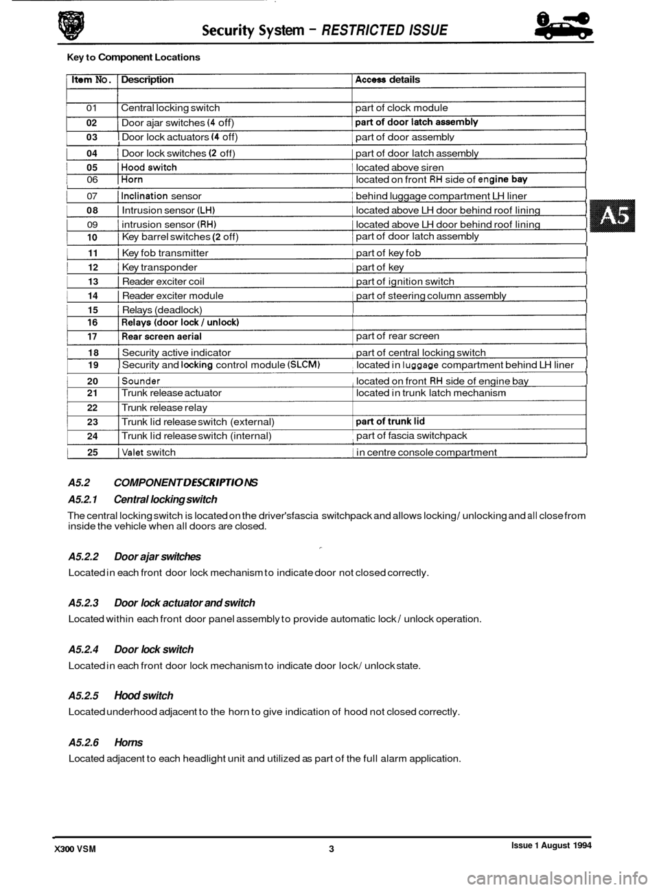
A5.2 COMPONENT DESCR/PT/O NS I
stem - RESTRICTED ISSUE
Key to Component Locations
Item No. Description Access details
01 Central locking switch part of clock module
02
1 I
Door ajar switches (4 off)
I I
part of rear screen
I 21 I Trunk release actuator located in trunk latch mechanism
22 I Trunk release relay
23
24 I Trunk lid release switch (external)
I Trunk lid release switch (internal) part of
fascia switchpack ,
A5.2.1 Central locking switch
A5.2.2 Door ajar switches
Located in each front door lock mechanism to indicate door not closed correctly.
-
The central locking switch is located on the driver'sfascia switchpack and allows locking / unlocking and all close from
inside the vehicle when all doors are closed.
A5.2.3
Located within each front door panel assembly to provide automatic lock / unlock operation.
Door lock actuator and switch
A5.2.4 Door lock switch
Located in each front door lock mechanism to indicate door lock/ unlock state.
A5.2.5 Hood switch
Located underhood adjacent to the horn to give indication of hood not closed correctly.
A5.2.6 Horns
Located adjacent to each headlight unit and utilized as part of the full alarm application.