crossmember JAGUAR XJ6 1994 2.G Workshop Manual
[x] Cancel search | Manufacturer: JAGUAR, Model Year: 1994, Model line: XJ6, Model: JAGUAR XJ6 1994 2.GPages: 521, PDF Size: 17.35 MB
Page 33 of 521
gg Jacking, Lifting & Vehicle Recovery
.-
- 2.1.4.1
Front - One Wheel
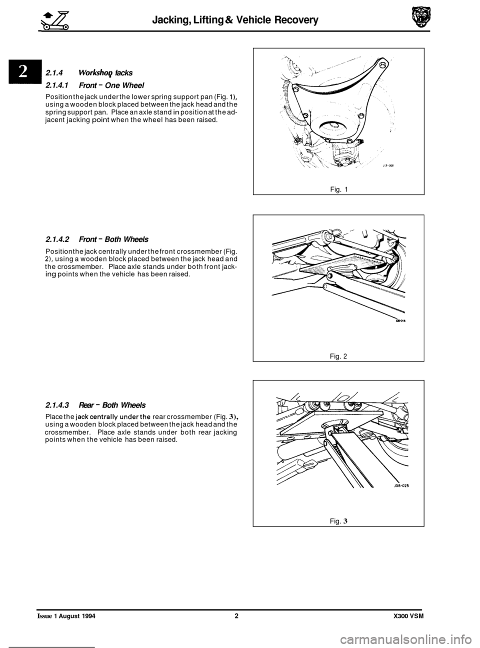
Position the jack under the lower spring support pan (Fig. I), using a wooden block placed between the jack head and the
spring support pan. Place an axle stand
in position at the ad- jacent jacking point when the wheel has been raised.
2.1.4.2 Front - Both Wheels
Position the jack centrally under the front crossmember (Fig. 2), using a wooden block placed between the jack head and
the crossmember. Place axle stands under both front jack- ing points when the vehicle has been raised.
2.1.4.3 Rear - Both Wheels
Place the jackcentrally underthe rear crossmember (Fig. 3), using a wooden block placed between the jack head and the
crossmember. Place axle stands under both rear jacking
points when the vehicle has been raised.
I 2.1.4 WorkshoD lacks
Fig. 1
Fig. 2
Fig. 3
Issue 1 August 1994 2 X300 VSM
Page 43 of 521
Engine (AJ16)
3.1.2 ENGlNE/ TRANSMlSSlON UN/& RENEW
SRO 12.41.02/20
The engine/transmission unit on the AJ 16 normally aspirated and supercharged engined vehicles are fitted ontothree
engine mounting/bracket assemblies. The two front engine mountings for the 3.2/4.0 liter normally aspirated and the
4.0 liter supercharged engined vehicles are identical. They are fitted to the front crossmember on either side of the
engine bay. Rubber to metal
engine/transmission rear mounts used for both engine types, are secured to a support
bracket which traverses the two body underframe longitudinal members. For access to remove the engine carry out the following procedures:
WARNING: WHEN WORKING WlTHlN THE ENGINE COMPARTMENT, KEEP CLEAR OF THE RADIATOR COOLING
FANS AS THEY COULD START WITHOUT WARNING EVEN IF THE ENGINE IS NOT RUNNING.
. Remove the hood, see SRO 76.16.01, section 13
. Remove the air cleaner assembly.
. Depressurize the fuel system, see SRO 19.50.02, section 5.1.
Disconnect the battery.
. In line with the relevant SRO's and sections, remove all appropriate obstructing parts, including their fixing and
. Disconnect all mechanical and isolate all electrical linkages leading to and from the engine.
. De-gas the airconditioning system, see section 14, Charge Recovery (System depressurization).
mounting
arrangements.
CAUTION : Do not vent refrigerant directly to the atmosphere and always use Jaguar approved recovery/recycle/re- charge equipment.
. Drain the engine oil, see 3.1.3 this section.
. Drain the coolant, see SRO 26.10.01, section 4.1.
WARNING: DO NOT REMOVE THE HEADER TANK PRESSURE CAP WHILE THE ENGINE IS HOT. IF THE CAP MUST
BE REMOVED, PROTECT THE HANDS AGAINST ESCAPING STEAM AND SLOWLY TURN THE CAP ANTI- CLOCKWISE UNTILTHE EXCESS PRESSURE CAN ESCAPE. LEAVETHE CAP IN THIS POSITION UNTIL ALL
STEAM AND PRESSURE HAS ESCAPED AND THEN REMOVE THE CAP COMPLETELY.
Before lifting the complete engine/transmission unit with an engine hoist from the engine bay, ensure that two engine
lifting brackets (tool 18G. 1465) are secured equally spaced to the inlet manifold studs. The engine lifting brackets
should be positioned towards the front and the rear of the assembly. Ensure the front of the vehicle is jacked
up secure- ly on stands when removing the assembly.
e
0
0
X300 VSM Issue 1 August 1994 2
Page 45 of 521
Engine (AJ16)
3.1.5 FRONT ENGINEMOUNTING BRACKETASSEMBLY, RENEW
SRO 12.45.01 LH
SRO 12.45.03 RH
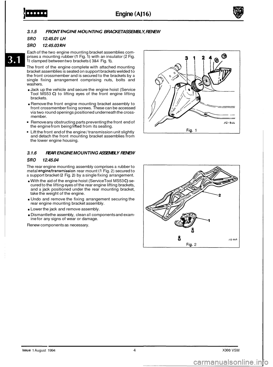
Each of the two engine mounting bracket assemblies com- prises a mounting rubber (1 Fig. 1) with an insulator (2 Fig.
1) clamped between two brackets ( 3&4 Fig. I).
The front of the engine complete with attached mounting
bracket assemblies is seated on support brackets welded to
the front crossmember and is secured to the brackets by
a single fixing arrangement comprising nuts, bolts and
washers.
. Jack up the vehicle and secure the engine hoist (Service
Tool MS53 C) to lifting eyes of the front engine lifting
brackets.
. Remove the front engine mounting bracket assembly to
front crossmember fixing screws. These can be accessed
via
two round openings positioned underneath the cross- member.
= Remove any obstructing parts preventing the front end of
the engine from being lifted from its seating.
Lift the front end of the engine / transmission unit slightly
and detach the front mounting bracket assemblies from
the lower engine housing.
3.1.6
SRO 12.45.04 REAR
ENGINE MOUNTING ASSEMBLY RENEW
The rear engine mounting assembly comprises a rubber to
metal engine/transmission rear mount (1 Fig. 2) secured to a support bracket (2 Fig. 2) by a single fixing arrangement.
. With the aid of the engine hoist (Service Tool MS53 C) se- cured to the lifting eyes of the rear engine lifting brackets,
and a jack positioned under the rear mounting bracket,
take the weight of the engine.
. Undo and remove the fixing arrangement securing the
rear engine mounting bracket assembly.
. Lower the jack and remove assembly.
. Dismantle the assembly, clean all components and exam- ine for any signs of wear or damage.
Renew components as necessary.
J12-8LL
Fig. 1
J 12- 8 LS
Fig. 2
8
Issue 1 August 1994 4 X300 VSM
Page 49 of 521
3.2.2 ENGINE - GEARBOX/ TRANSMISSION
ASSEMBLY, RENEW
SRO 12.37.01/90
The engine /transmission unit on the V12 6.0 liter model is mounted on three engine mounting / bracket assemblies
fitted to the front crossmember on either side of the engine bay. The engine/ transmission rear mount is a mounting
bracket and spring assembly fitted and secured to body underframe longitudinal members. For access to remove the
engine carry
out the following procedures:
WARNING: WHEN WORKING WITHIN THE ENGINE COMPARTMENT, KEEP CLEAR OF THE RADIATOR COOLING
FANS AS THEY COULD START WITHOUT WARNING, EVEN IF THE ENGINE IS NOT RUNNING.
. Remove the hood, see SRO 76.16.01, section 13.
. Remove the two air cleaner assemblies, see SRO’s 19.10.01 & 19.10.02.
. Remove the engine cover, see SRO 12.29.93 (V12 Engine Service Manual).
Depressurize the fuel system, see SRO 19.50.02, section 5.1.
In line with the relevant SRO’s and sections, remove all appropriate obstructing parts, including their fixing and
. Disconnect all mechanical and isolate all electrical linkages leading to and from the engine.
. De-gas the air conditioning system, see section 14, Charge Recovery (System depressurization).
Disconnect
the battery.
mounting arrangements.
CAUTION: Do
not vent refrigerant directly to the atmosphere and always use Jaguar approved recovery/recycle/ra charge equipment.
Drain the engine oil, see 3.2.3 this section.
Drain the coolant, see SRO 26.10.01, section 4.1.
WARNING: DO NOT REMOVE THE HEADER TANK PRESSURE CAP WHILE THE ENGINE IS HOT. IF THE CAP MUST
BE REMOVED, PROTECT THE HANDS AGAINST ESCAPING STEAM AND SLOWLY TURN THE CAP ANTI- CLOCKWISE UNTIL THE EXCESS PRESSURE CAN ESCAPE. LEAVE THE CAP IN THIS POSITION UNTIL ALL
STEAM AND PRESSURE HAS ESCAPED AND THEN REMOVE THE CAP COMPLETELY.
Before
lifting the complete engine/transmission unit with an engine hoist from the engine bay, ensure that two engine
lifting brackets (tool 18G. 1465) are secured equallyspaced to the inlet manifold studs. The four engine lifting brackets
should be positioned towards the front and the rear of the assembly. Ensure the front of thevehicle is jacked
up secure- ly on stands when removing the assembly.
X300 VSM Issue 1 August 1994 2
Page 51 of 521
Engine (V12)
3.2.5 OIL COOLER, RENEW
SRO 12.60.68
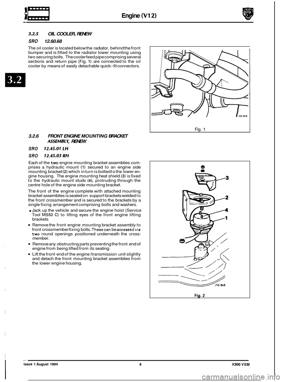
The oil cooler is located below the radiator, behind the front
bumper and is fitted to the radiator lower mounting using
two securing bolts. The cooler feed pipe comprising several
sections and return pipe (Fig.
1) are connected to the oil
cooler by means of easily detachable quick
-fit connectors.
3.2.6 FRONT ENGINE MOUNTING BRACKET
SRO 12.45.01 LH
SRO 12.45.03 RH
Each of the two engine mounting bracket assemblies com- prises a hydraulic mount (1) secured to an engine side
mounting bracket (2) which in turn is bolted to the lower en- gine housing. The engine mounting heat shield (3) is fixed
to the hydraulic mount studs (41, protruding through the
centre hole of the engine side mounting bracket.
The front of the engine complete with attached mounting
bracket assemblies is seated on support brackets welded to
the front crossmember and is secured to the brackets by a
single fixing arrangement comprising bolts and washers.
. Jack up the vehicle and secure the engine hoist (Service
Tool MS53 C) to lifting eyes of the front engine lifting
brackets
Remove the front engine mounting bracket assembly to
front crossmember fixing bolts.
Thesecan be accessedvia two round openings positioned underneath the cross- member.
Remove any obstructing parts preventing the front end of
engine from being lifted from its seating.
Lift the front end of the engine /transmission unit slightly
and detach the front mounting bracket assemblies from
the lower engine housing.
ASSEMBLV, RENEW
Fig. 1
4 X300 VSM Issue 1 August 1994
Page 183 of 521
-5 Driveshafts & Final Drive
0
Fixing
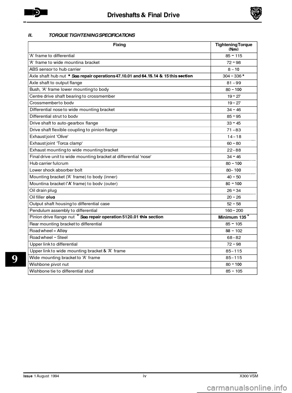
11. TORQUE TIGHTENING SPECIFICATIONS
Tightening Torque
(Nm)
'A' frame to differential 85 - 115
'A' frame to wide mountina bracket 72 - 98
ABS sensor to hub carrier
Axle shaft hub nut
* See repair operations 47.10.01 and 64.15.14 & 15 this don
8- 10
304 - 336 *
Axle shaft to output flange
Bush,
'A' frame lower mounting to body
81 -99
80
- 100
Centre drive shaft bearing to crossmember 19 - 27
Crossmember to bodv 19 - 27
Differential nose to wide mounting bracket - 34 - 46
Issue 1 August 1994 iv X300 VSM
Differential strut to bodv 85 - 95
Drive shaft to auto-gearbox flange
Drive shaft flexible coupling to pinion flange 33 - 45
71
-83
Exhaust joint 'Olive'
Exhaust joint 'Torca clamp' -. 14-18
60
- 80
Exhaust mounting to wide mounting bracket
Final drive unit to wide mounting bracket at differential 'nose'
Hub carrier fulcrum 22-88
34
- 46
80
- 100 ___
Lower shock absorber bolt
Mounting bracket
('A' frame) to body (inner)
Mountina bracket
('A' frame) to bodv (outer)
- 80- 100
40 - 50
80 - 100
Oil drain plug __ 26 - 34
Oil filler DIU~ 20 - 26
Output shaft housing to differential case
Pendulum assembly to differential
Pinion drive flange nut
* See repair operation 5120.01 this section
Road wheel -Alloy
Road wheel - Steel
Upper link to differential
Rear
mounting bracket to differential
52 - 58
160
- 200
Minimum 135 *
85 - 105
88 - 102
68
-82
72
- 98 ~~~~~
Upper
link to wide mounting bracket & 'A' frame
Wide mounting bracket to
'A' frame
85-115
85
-115
Wishbone pivot nut
Wishbone tie to differential stud 80 - 100
85 - 105
Page 187 of 521
Driveshafts & Final Drive
9.2 DRIVE SHAm, ALIGN
SRO 47.15.51
CAUTION: To preserve 'drive line' refinement, individual parts, other than fixings, MUST NOT be renewed. In the
event of any balance or drive shaft component related problem, the complete assembly must be renewed.
Under no circumstances must the flexible coupling (or its fixings) be loosened or removed from the drive
shaft flange.
Preliminary Checks
Before this procedure is actioned it is advisable to ensure that:
The gearbox mounting center stud is positioned centrally in relation to the crossmember inspection hole.
The crossmember is central on the body fixings and not 'hard over' to one side.
The differential spigot radial
run-out is within specification, see preliminary pages.
If the vehicle has been standing for
a period the tires may be 'flat-spotted'. If so, this will clear in approximate.;
400 km (250 miles). After this distance the source of vibration should be reassessed.
12 Cylinder
8 Remove exhaust center section.
All
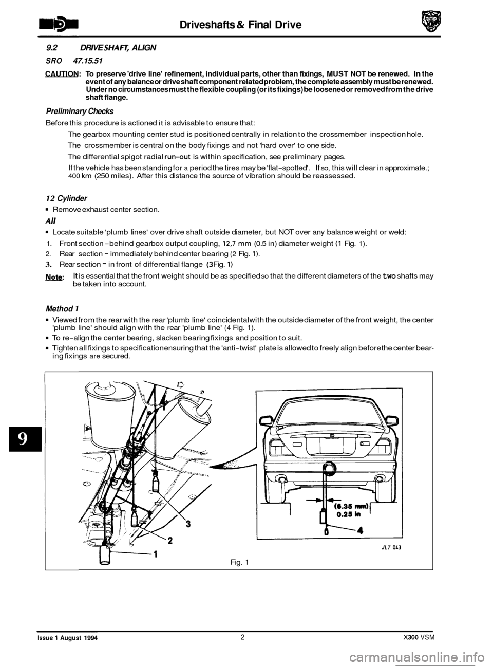
8 Locate suitable 'plumb lines' over drive shaft outside diameter, but NOT over any balance weight or weld:
1.
2.
3.
l\lnfe:
Front section -behind gearbox output coupling, 12,7 mm (0.5 in) diameter weight (1 Fig. 1).
Rear section - immediately behind center bearing (2 Fig. 1).
Rear section - in front of differential flange (3 Fig. 1)
It is essential that the front weight should be as specified so that the different diameters of the two shafts may
be taken into account.
Method 1
8 Viewed from the rear with the rear 'plumb line' coincidental with the outside diameter of the front weight, the center
8 To re-align the center bearing, slacken bearing fixings and position to suit.
8 Tighten all fixings to specification ensuring that the 'anti-twist' plate is allowed to freely align before the center bear-
'plumb line' should align with the rear 'plumb line' (4 Fig. 1).
ing fixings are secured.
Fig. 1
1
JL7 OL3
0
0
0
0 ~~~~
Issue 1 August 1994 2 X300 VSM
Page 189 of 521
Driveshafts & Final Drive
9.3
SRO 51.10.24
Disconnect vehicle battery ground lead.
. Support the vehicle at the rear.
OUTPUT SHAFT END FLOAT, CHECK
Mount a dial test indicator (DTI) to the differential housing with the probe resting on the output shaft flange (DTI probe must be parallel to the output shaft center line and NOT at an angle).
. Push the wheel 1 shaft assembly inwards and zero the DTI; pull outwards and note the reading.
. If the end float exceeds 0,15 mm; firstly verify the shim preload and if this is found to be correct, renew the output
shaft bearing. See 51.10.22. this section, for shim check and renew operations.
9.4
SRO 51.20.19
rn Disconnect vehicle battery ground lead.
See operation 51.10.22. this section, for process detail, less bearing 1 oil seal renew.
OUTPUT SHAFT HOUSING ‘0’ RING, RENEW
Prior to removal of shaft assembly check output shaft end float in accordance with operation 51.10.24.
9.5 OIL SEAL - PINION FLANGE, RENEW
SRO 51.20.01
. Disconnect vehicle battery ground lead.
. Support the vehicle at the rear.
. Disconnect main handbrake cable at compensator.
’Match mark‘ the FLEXIBLE COUPLING to the differential DRIVE FLANGE and remove fixings.
Remove fixings center bearing to crossmember and push drive shaft rear section forward to disengage from pinion
spigot.
CAUTION: Under no circumstances must the flexible coupling (or its fixings) be loosened or removed from the drive
shaft flange.
Support the drive shaft, do not allow it to hang.
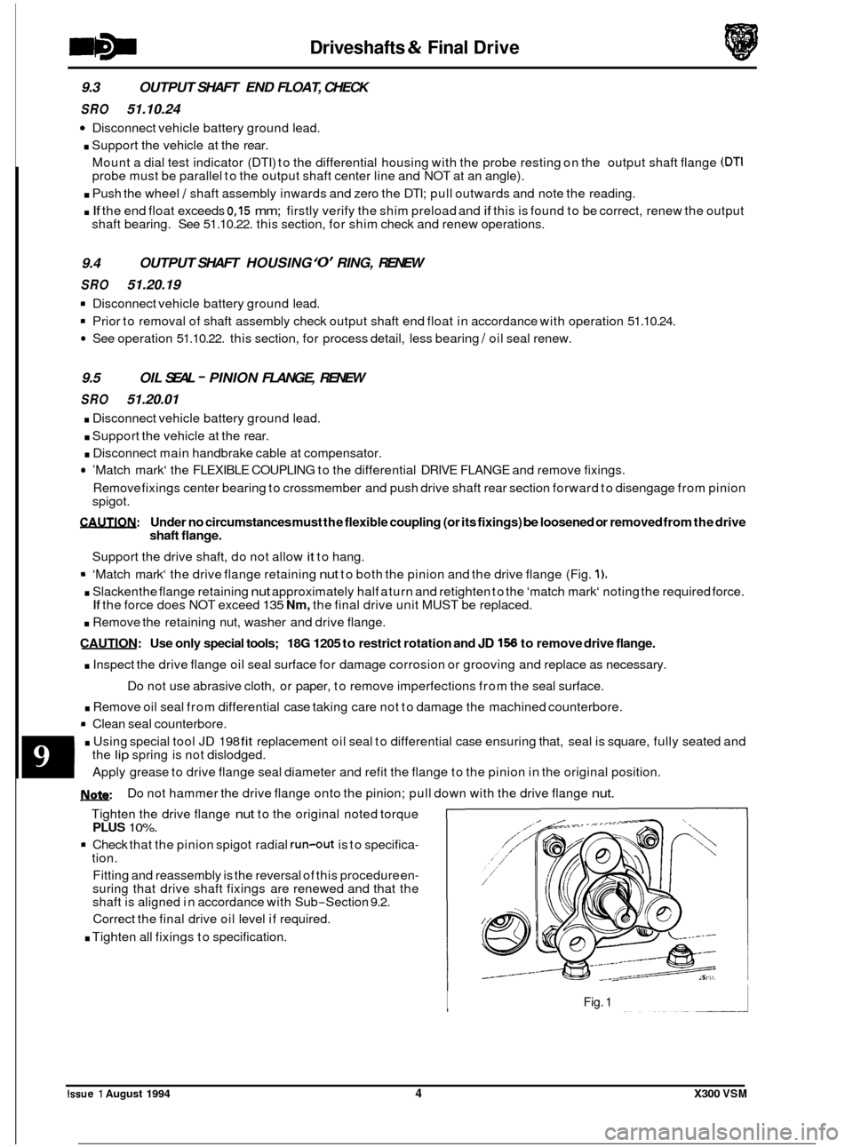
9 ‘Match mark‘ the drive flange retaining nut to both the pinion and the drive flange (Fig. 1).
. Slacken the flange retaining nut approximately half a turn and retighten to the ‘match mark‘ noting the required force.
. Remove the retaining nut, washer and drive flange.
CAUTION: Use only special tools; 18G 1205 to restrict rotation and JD 156 to remove drive flange.
. Inspect the drive flange oil seal surface for damage corrosion or grooving and replace as necessary.
. Remove oil seal from differential case taking care not to damage the machined counterbore.
rn Clean seal counterbore.
. Using special tool JD 198 fit replacement oil seal to differential case ensuring that, seal is square, fully seated and
If the force does NOT exceed 135 Nm, the final drive unit MUST be replaced.
Do not use abrasive cloth, or paper, to remove imperfections from the seal surface.
the
lip spring is not dislodged.
Apply grease to drive flange seal diameter and refit the flange to the pinion in the original position.
U: Do not hammer the drive flange onto the pinion; pull down with the drive flange nut.
Tighten the drive flange nut to the original noted torque PLUS 10%.
* Check that the pinion spigot radial run-out is to specifica- tion.
Fitting and reassembly is the reversal of this procedure en
- suring that drive shaft fixings are renewed and that the
shaft is aligned in accordance with Sub-Section 9.2.
Correct the final drive oil level if required.
. Tighten all fixings to specification.
Fig. 1
0
Issue 1 August 1994 4 X300 VSM
Page 191 of 521
Driveshafts & Final Drive
9.8 FINAL DRWE UNIT RENEW
SRO 51.25.13
. Disconnect vehicle battery ground lead.
. Support the vehicle at the rear and remove the rear road
wheels.
Disconnect brake pad wear sensor multi-plug at RH hub
carrier and remove tie straps from wishbone. Release
ABS speed sensors at
RH and LH hub carriers and remove
tie straps from wishbones.
. Remove rear brake calipers, see Section 12, and support
at bump stop. Disconnect main handbrake cable at com- pensator, short cables at joining piece and remove com- pensator.
. Remove fixings, FLEXIBLE coupling to differential DRIVE FLANGE.
CAUTIW: Under no circumstances must the flexible
coupling (or itsfixings) be loosened or removed
from the drive shaft flange.
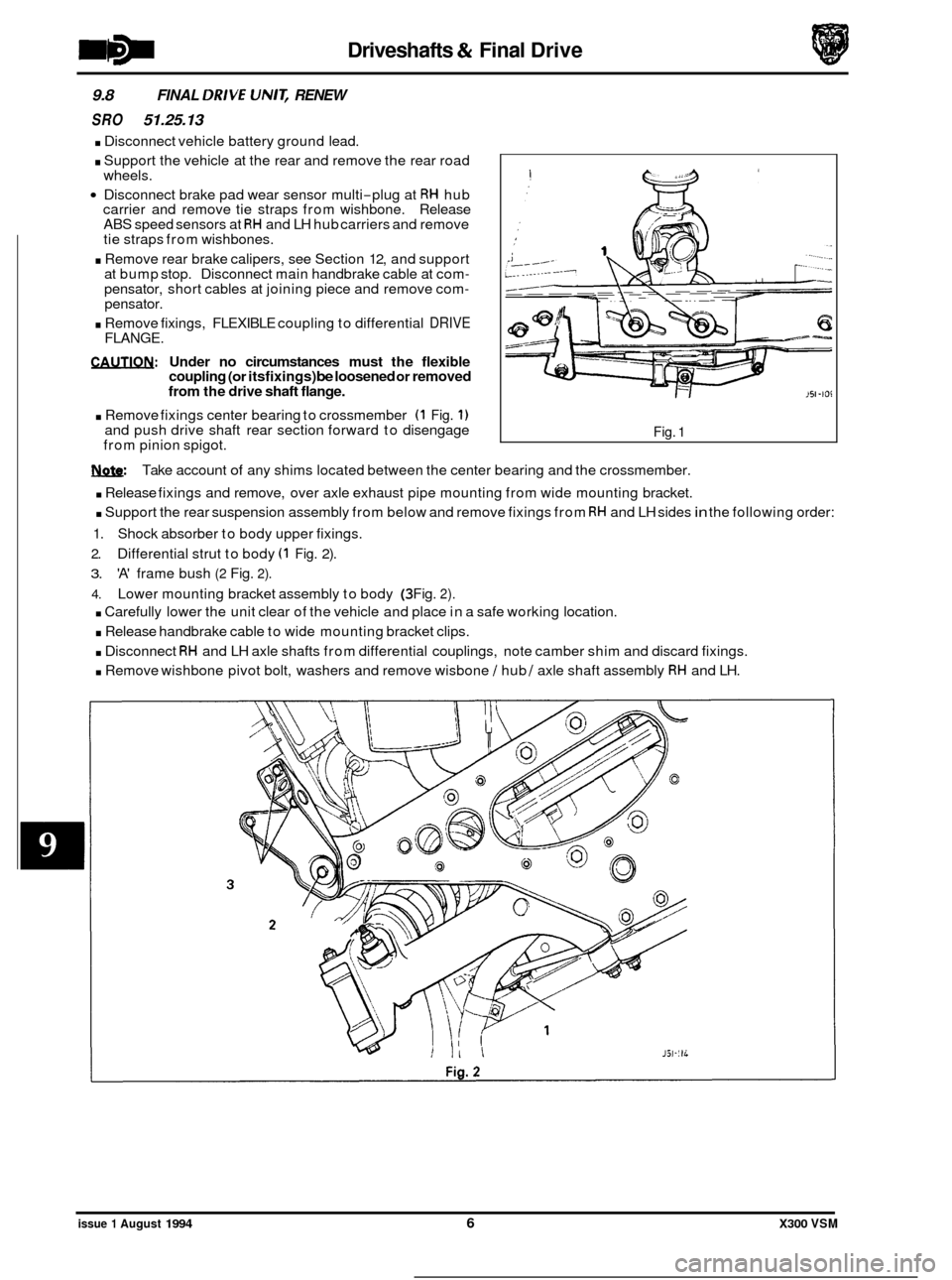
. Remove fixings center bearing to crossmember (1 Fig. 1) and push drive shaft rear section forward to disengage
from pinion spigot. Fig. 1
w: Take account of any shims located between the center bearing and the crossmember.
. Release fixings and remove, over axle exhaust pipe mounting from wide mounting bracket.
. Support the rear suspension assembly from below and remove fixings from RH and LH sides in the following order:
1. Shock absorber to body upper fixings.
2. Differential strut to body (1 Fig. 2).
3. 'A' frame bush (2 Fig. 2).
4. Lower mounting bracket assembly to body (3 Fig. 2).
. Carefully lower the unit clear of the vehicle and place in a safe working location.
. Release handbrake cable to wide mounting bracket clips.
. Disconnect RH and LH axle shafts from differential couplings, note camber shim and discard fixings.
. Remove wishbone pivot bolt, washers and remove wisbone / hub / axle shaft assembly RH and LH.
issue 1 August 1994 6 X300 VSM
Page 198 of 521
TORQUE TIGHTENING SPECIFICATIONS
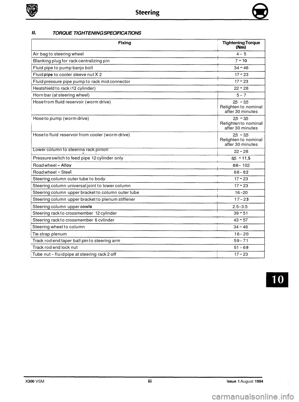
Fixing Tightening Torque
(Nm)
Air bag to steering wheel
Blanking plug for rack centralizing pin 4-5
7
- 10
Fluid pipe to pump banjo bolt
Fluid
pipe to cooler sleeve nut X 2 34
- 46
17
- 23
Fluid pressure pipe pump to rack mid connector
Heatshield to rack
(12 cvlinder)
17 - 23
22
- 28
Horn bar (at steering wheel)
Hose from
fluid reservoir (worm drive)
Hose
to pump (worm drive)
Hose to fluid reservoir from cooler (worm drive)
Lower column to steerina rack pinion
5-7
2,5
- 3,5
Retighten to nominal
after 30 minutes
Retighten to nominal
after
30 minutes
Retighten to nominal
after
30 minutes
2,5 - 3,5
2,5
- 3,5
22
- 28
Pressure switch to feed pipe 12 cylinder only 8,5 - 11,5
Road wheel -Alloy 88- 102
Road wheel - Steel 68-82
Steering column outer tube to bodv 17 - 23
Steering column universal joint to lower column
Steering column upper bracket to column outer tube
Steering column upper bracket to plenum stiffener 17 - 23
16
-20
17
-23 ~~
I Steering
column upper COWIS I ~ 2.5-3.5
Steering
rack to crossmember 12 cylinder
Steering rack to crossmember
6 cvlinder
39 - 51
43
- 57
Steering wheel to column 34 - 46
Tie strap plenum 16-20
Track rod end taper ball pin to steering arm
Track rod end lock nut 59-71
51
-69
17
- 23 Tube nut -fluid pipe at steering rack 2 off
X300 VSM iii Issue 1 August 1994