fuel type JAGUAR XJ6 1994 2.G Workshop Manual
[x] Cancel search | Manufacturer: JAGUAR, Model Year: 1994, Model line: XJ6, Model: JAGUAR XJ6 1994 2.GPages: 521, PDF Size: 17.35 MB
Page 43 of 521
Engine (AJ16)
3.1.2 ENGlNE/ TRANSMlSSlON UN/& RENEW
SRO 12.41.02/20
The engine/transmission unit on the AJ 16 normally aspirated and supercharged engined vehicles are fitted ontothree
engine mounting/bracket assemblies. The two front engine mountings for the 3.2/4.0 liter normally aspirated and the
4.0 liter supercharged engined vehicles are identical. They are fitted to the front crossmember on either side of the
engine bay. Rubber to metal
engine/transmission rear mounts used for both engine types, are secured to a support
bracket which traverses the two body underframe longitudinal members. For access to remove the engine carry out the following procedures:
WARNING: WHEN WORKING WlTHlN THE ENGINE COMPARTMENT, KEEP CLEAR OF THE RADIATOR COOLING
FANS AS THEY COULD START WITHOUT WARNING EVEN IF THE ENGINE IS NOT RUNNING.
. Remove the hood, see SRO 76.16.01, section 13
. Remove the air cleaner assembly.
. Depressurize the fuel system, see SRO 19.50.02, section 5.1.
Disconnect the battery.
. In line with the relevant SRO's and sections, remove all appropriate obstructing parts, including their fixing and
. Disconnect all mechanical and isolate all electrical linkages leading to and from the engine.
. De-gas the airconditioning system, see section 14, Charge Recovery (System depressurization).
mounting
arrangements.
CAUTION : Do not vent refrigerant directly to the atmosphere and always use Jaguar approved recovery/recycle/re- charge equipment.
. Drain the engine oil, see 3.1.3 this section.
. Drain the coolant, see SRO 26.10.01, section 4.1.
WARNING: DO NOT REMOVE THE HEADER TANK PRESSURE CAP WHILE THE ENGINE IS HOT. IF THE CAP MUST
BE REMOVED, PROTECT THE HANDS AGAINST ESCAPING STEAM AND SLOWLY TURN THE CAP ANTI- CLOCKWISE UNTILTHE EXCESS PRESSURE CAN ESCAPE. LEAVETHE CAP IN THIS POSITION UNTIL ALL
STEAM AND PRESSURE HAS ESCAPED AND THEN REMOVE THE CAP COMPLETELY.
Before lifting the complete engine/transmission unit with an engine hoist from the engine bay, ensure that two engine
lifting brackets (tool 18G. 1465) are secured equally spaced to the inlet manifold studs. The engine lifting brackets
should be positioned towards the front and the rear of the assembly. Ensure the front of the vehicle is jacked
up secure- ly on stands when removing the assembly.
e
0
0
X300 VSM Issue 1 August 1994 2
Page 76 of 521
striker and the-fuel cap stowage magnet.
The fuel bowl, retained around the filler neck by a clip, containing a drain tube filter located over the mating drain tube,
is rubber moulded onto a steel armature and fitted to the BIW decking panel by five M5 nuts.
The fuel lid latching assembly fitted to the metal armature of the fuel bowl by an M5 nut, includes the locking pin and
the operating actuator.
The actuator operates from the central locking system driven by the security and locking control module
(SLCM).
The fuel tank, mounted across thevehicle behind the passenger compartment rear bulkhead, is held in position by two
retaining straps, tightened by two M5 fixing arrangements.
The fuel tank of AJ16 engined vehicles contains one fuel pump, supplying fuel to the normally aspirated engine and
two fuel pumps, supplyingfuel to the supercharged engine. They are regenerative turbine pumps supplied by
Nippon- Denso. Nominal operating pressure is 3 bar (3.7 bar for supercharged engine) above the manifold depression and
pump delivery is 90 litredhour minimum at 13.2 volts, 3 bar outlet pressure. The pump(s) draw a nominal current of 7 amperes at 13 volts, 3 bar outlet pressure, ambient temperatures. Built in to the pump assembly is a over-pressure
relief valve which blows at 4.5 - 8.5 bar.
Fuel is drawn by the pumps from the fuel tank and is then supplied to the fuel rail via a
70 micron filter and the fuel
feed line connected in series by fuel filter.
The amount of fuel being injected into the engine
is controlled by the fuel injectors combined with the engine control module (ECM). - Any excessive fuel flowing through the system, is returned to the fuel tankvia the fuel regulator valve mounted on the
fuel rail, the fuel return line and the check valve also located inside the tank.
The two filters prevent contaminants from entering the fuel rail and possible damage to the fuel injectors, the engine,
the pump and the underfloor filter.
The fuel pumps are switched on and off by relays controlled by the engine control module
(ECM).
The second fuel pump for the supercharged engine operates only in the higher speed range, switching on at 4000rpm and off at 3200rpm.
The fuel lines are made up of an assembly, combining steel under floor pipes and flexible conductive anti-permeation
tubing. In orderto perform speedy remove and refit operations, the underfloor steel lines are linked through the engine
bay bulkhead to the flexible tubing, leading to the fuel rail and the fuel regulator by using positive sealing, quick-fit
type connectors. The same type connectors, are used to connect the fuel feed and return line to the fuel tank.
Connectors used inside the engine bay are of different sizes tocorrespond with the difference in pipe diameter, whereas
the connectors for the feed and return lines at the fuel tank are the same size.
Except for the return line connector at the fuel tank, two release tools, one for each size of connector are required to
release all remaining connectors.
-~
Fuel, Emission Control & Engine Management (AJ16)
5.1.2 GENERAL DESCRIPTION
m: WORKING ON THE FUEL SYSTEM MAY RESULT IN FUEL AND FUEL VAPOUR BEING PRESENT IN THE
ATMOSPHERE. FUEL VAPOUR IS EXTREMELY FLAMMABLE, HENCE GREAT CARE MUST BE TAKEN WHllST WORKING ON THE FUEL SYSTEM. ADHERE STRICTLY TO THE FOLLOWING PRECAUTIONS:
DO NOT
SMOEIN THE WORK AREA.
DISPLAY 'NO SMOKING
' SIGNS AROUND THE AREA.
ENSURE THAT A
CO2 FIRE EXTINGUISHER IS CLOSE AT HAND.
ENSURE THAT DRY SAND
IS AVAILABLE TO SOAK UP ANY FUEL SPILLAGE.
EMPTY FUEL USING SUITABLE FIRE
PROOF EQUIPMENT INTO AN AUTHORIZED EXPLOSIOWROOF
CONTAINER.
DO NOT EMPTY FUEL
INTO A PIT.
ENSURE THAT WORKING AREA
IS WELL VENTILATED.
ENSURE THAT ANY WORK ON THE FUEL SYSTEM
IS ONLY CARRIED OUT BY EXPERIENCED AND WELL
QUALIFIED MAINTENANCE PERSONNEL.
The fuel filler assembly, supplied complete with serviceable lid, hinge and hinge spring, is fixed to the Body-in-White
(BIW) decking panel by two M5 nuts. Additional parts of the assembly comprise a adjustable rubber buffer, a snap-in
X300 VSM 3 Issue 1 August 1994
Page 92 of 521
striker and the fuel cap stowage magnet.
The fuel bowl, retained around the filler neck by a clip, containing a drain tube filter located
overthe mating drain tube,
is rubber moulded onto a steel armature and fitted to the BIW decking panel. by five M5 nuts.
The fuel lid latching assembly fitted to the metal armature of the fuel bowl by an M5 nut, includes the locking pin and
the operating actuator.
The actuator operates from the central locking system driven by the Security and Locking Control Module (SLCM).
The fuel tank, mounted across the vehicle behind the passenger compartment rear bulkhead, is held in position by two
retaining straps, tightened by two M5 fixing arrangements.
VI2 engined vehicles are equipped with two fuel pumps located inside the tank. They are regenerative turbine pumps
supplied by Nippon Denso. Nominal operating pressure is 3 bar above the manifold depression and pump delivery
is 90 litres/hour minimum at 13.2 volts, 3 bar outlet pressure. The pump draws a nominal current of 7 amperes at 13 volts, 3 bar outlet pressure, ambient temperatures. Built in to the pump assembly is a over-pressure relief valve which
blows at 4.5 - 8.5 bar.
Fuel is drawn by the pumps from the fuel tank and is then supplied to the fuel rail via a
70 micron filter and the fuel
feed line connected in series by fuel filter.
The amount of fuel being injected into the engine is controlled by the fuel injectors combined with the engine control
module (ECM).
Any excessive fuel flowing through the system, is returned to thefuel tankvia the fuel regulator valve mounted on the
fuel rail, the fuel return line and the check valve also located inside the tank.
The two filters prevent contaminants from entering the fuel rail and possible damage to the fuel injectors, the engine,
the pump and underfloor filter.
The second fuel pump is controlled by the engine control module
(ECM) and works of a mapped fuel map. The pumps
'switch on' time depends on the fuel requirement which is depending on the engine load.
The fuel lines are made up of an assembly, combining steel underfloor pipes and flexible conductive anti
-permeation
tubing. In order to perform speedy remove and refit operations, the underfloor steel lines are linked through the engine
bay bulkhead to theflexibletubing, leading to the fuel rail and the fuel regulator by using positive sealing, quick
fit type
connectors. The same type connectors, are used to connect the fuel feed and return line to the fuel tank.
Connectors used inside the engine bay, are of different sizes to correspond with the difference in pipe diameter, where
- as the connectors for the feed and return lines at the fuel tank are the same size.
Except for the return line connector at the fuel tank, two release tools, one for each size of connector, are required to
release all remaining connectors.
Fuel, Emission Control & Engine Management (V12)
5.2.2 GENERAL DESCRIPTION
WARNING: WORKING ON THE FUEL SYSTEM RESULTS IN FUEL AND FUEL VAPOUR BEING PRESENT IN THE AT- MOSPHERE. FUEL VAPOUR IS EXTREMELY FLAMMABLE, HENCE GREAT CARE MUST BE TAKEN WHILST
WORKING ON THE FUEL SYSTEM. ADHERE STRICTLY TO THE FOLLOWING PRECAUTIONS:
PO NOT SMOKF, IN THE WORK AREA.
DISPLAY 'NO SMOKING
' SIGNS AROUND THE AREA.
ENSURE THAT A
CO2 FIRE EXTINGUISHER IS CLOSE AT HAND.
ENSURE THAT DRY SAND
IS AVAILABLE TO SOAK UP ANY FUEL SPILLAGE.
EMPTY FUEL USING SUITABLE FIRE PROOF EQUIPMENT INTO AN AUTHORIZED EXPLOSION PROOF
CONTAINER.
DO NOT EMPTY FUEL INTO A PIT.
ENSURE THAT WORKING AREA IS WELL VENTILATED.
ENSURE THAT ANY WORK ON THE FUEL SYSTEM
IS ONLY CARRIED OUT BY EXPERIENCED AND WELL
QUALIFIED MAINTENANCE PERSONNEL.
The fuel filler assembly, supplied complete with serviceable lid, hinge and hinge spring, is fixed to the Body-in-White (BIW) decking panel by two M5 nuts. Additional parts of the assembly comprise a adjustable rubber buffer, a snap-in
X300 VSM 3 Issue 1 August 1994
Page 351 of 521
IT Electrical
15.2.8 Odometer
With the ignition 'OFF' the odometer is permanently dis-
played but not illuminated. With the ignition 'ON' the odo- meter is displayed and also illuminated.
Trip information or driver information messages may be dis
-
played instead of the 'ODO'. By pressing the 'ODO' button
once or twice the trip and driver information messages can
be deleted and the
'ODO rdisplayed.
W. The odometer value is not stored within the LCD
module.
15.2.9 Trip Computev
This provides information on the vehicle's speed, fuel usage
and distance traveled
all of which are calculated by a micro
processor.
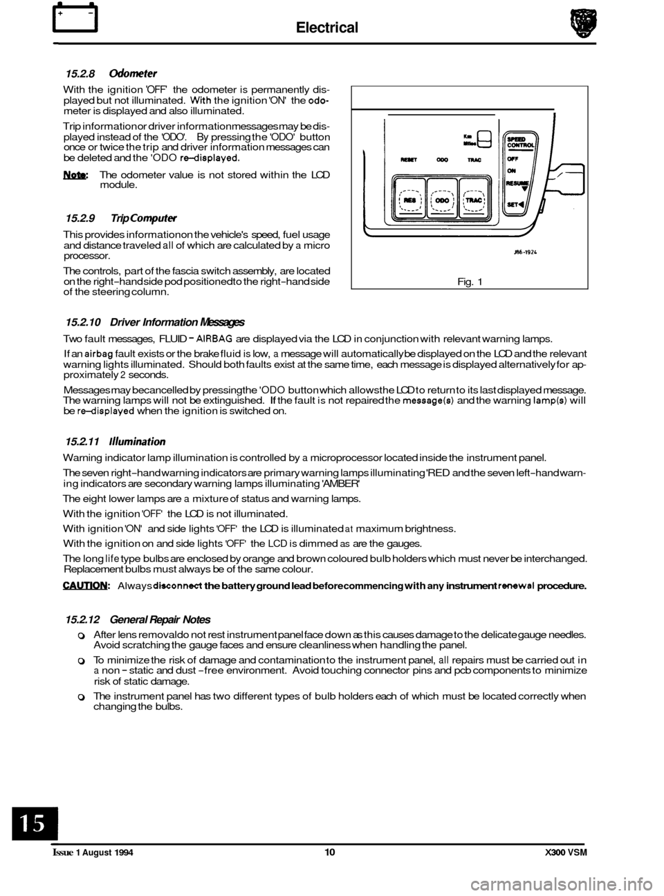
The controls, part of the fascia switch assembly, are located
on the right
-hand side pod positioned to the right-hand side
of the steering column.
I
/
J86-192L
Fig. 1
15.2.10 Driver Information Messages
Two fault messages, FLUID - AIRBAG are displayed via the LCD in conjunction with relevant warning lamps.
If an
airbag fault exists or the brake fluid is low, a message will automatically be displayed on the LCD and the relevant
warning lights illuminated. Should both faults exist at the same time, each message is displayed alternatively for ap
- proximately 2 seconds.
Messages may becancelled
by pressing the 'ODO button which allowsthe LCD to return to its last displayed message.
The warning lamps will not be extinguished. If the fault is not repaired the message(s) and the warning lamp(s) will
be redisplayed when the ignition is switched on.
15.2.11 /llumination
Warning indicator lamp illumination is controlled by a microprocessor located inside the instrument panel.
The seven right
-hand warning indicators are primary warning lamps illuminating 'RED and the seven left-hand warn-
ing indicators are secondary warning lamps illuminating 'AMBER'
The eight lower lamps are
a mixture of status and warning lamps.
With the ignition
'OFF' the LCD is not illuminated.
With ignition
'ON' and side lights 'OFF' the LCD is illuminated at maximum brightness.
With the ignition on and side lights
'OFF' the LCD is dimmed as are the gauges.
The long
life type bulbs are enclosed by orange and brown coloured bulb holders which must never be interchanged.
Replacement bulbs must always be of the same colour.
CAUTIQN: Always dwonnect the battery ground lead before commencing with any instrument rsimwal procedure.
15.2.12 General Repair Notes
0 After lens removal do not rest instrument panel face down as this causes damage to the delicate gauge needles.
Avoid scratching the gauge faces and ensure cleanliness when handling the panel.
0 To minimize the risk of damage and contamination to the instrument panel, all repairs must be carried out in a non - static and dust -free environment. Avoid touching connector pins and pcb components to minimize
risk of static damage.
0 The instrument panel has two different types of bulb holders each of which must be located correctly when
changing the bulbs.
Issue 1 August 1994 10 X300 VSM
Page 384 of 521
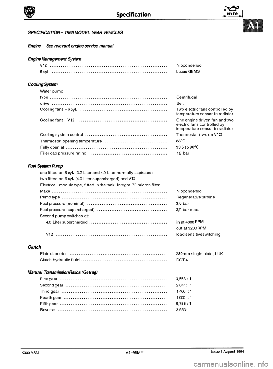
SPECIFICATION - 1995 MODEL YEAR VEHICLES
Engine See relevant engine service manual
Engine Management System
VI2 ............................................................... Nippondenso
6cyl. .............................................................. LucasGEMS
Cooling System
Water pump
type
............................................................... Centrifugal
Cooling fans
- 6 cyl. ................................................ Two electric fans controlled by
Cooling fans
- VI2 ................................................. One engine driven fan and two
Cooling system control
............................................. Thermostat (two on V12)
Thermostat opening temperature .................................... 88OC
Fully open at ....................................................... 93,5 to 96OC
Filler cap pressure rating ........................................... 1,2 bar
drive
.............................................................. Belt
temperature sensor in radiator
electric fans controlled by
temperature sensor
in radiator
Fuel System Pump
one fitted on 6 cyl. (3.2 Liter and 4.0 Liter normally aspirated)
two fitted on 6
cyl. (4.0 Liter supercharged) and VI2
Electrical, module type, fitted in the tank. Integral 70 micron filter.
Make
.............................................................. Nippondenso
Fuel pressure (nominal)
............................................ 3,O bar
Second
pump switches at:
Pump
type
......................................................... Regenerative turbine
Fuel pressure (supercharged)
....................................... 3,7 bar max.
4.0 Liter supercharged ........................................... in at 4000 RPM
out at 3200 RPM
VI2 ............................................................ load sensitiveswitching
Clutch
Plate diameter .....................................................
Clutch hydraulic fluid ............................................... DOT 4
280mm single plate, LUK
Manual Transmission Ratios (Gefragl
First gear .......................................................... 3,553:l
Second gear ....................................................... 2,041: 1
Third gear ......................................................... 1,400 : 1
Fourth gear
........................................................ 1,000 : 1
Fifth gear
.......................................................... 0,755:l
Reverse ........................................................... 3,553: 1
Issue 1 August 1994 X300 VSM AI-95MY 1
Page 391 of 521
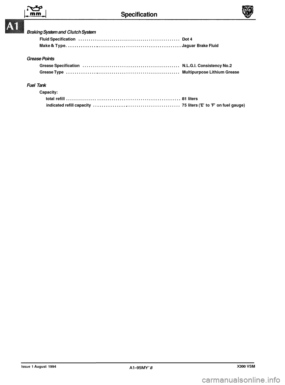
Braking System and Clutch System
Fluid Specification .........
Make & Type. ..............
Grease Points
Grease Specification .......
Grease Type ...............
Fuel Tank
Capacity:
total refill
...............
indicated refill capacity . .
Issue 1 August 1994
Specificat ion
..............
..............
..............
..............
..............
..............
...........
...........
...........
...........
...........
........... ...............
...............
...............
...............
...............
...............
Dot 4
Jaguar
Brake Fluid
N.L.G.I. Consistency
No.2
Multipurpose Lithium Grease
81 liters
75 liters
('E' to 'F' on fuel gauge)
A1-95MY '8 X300 VSM
Page 413 of 521
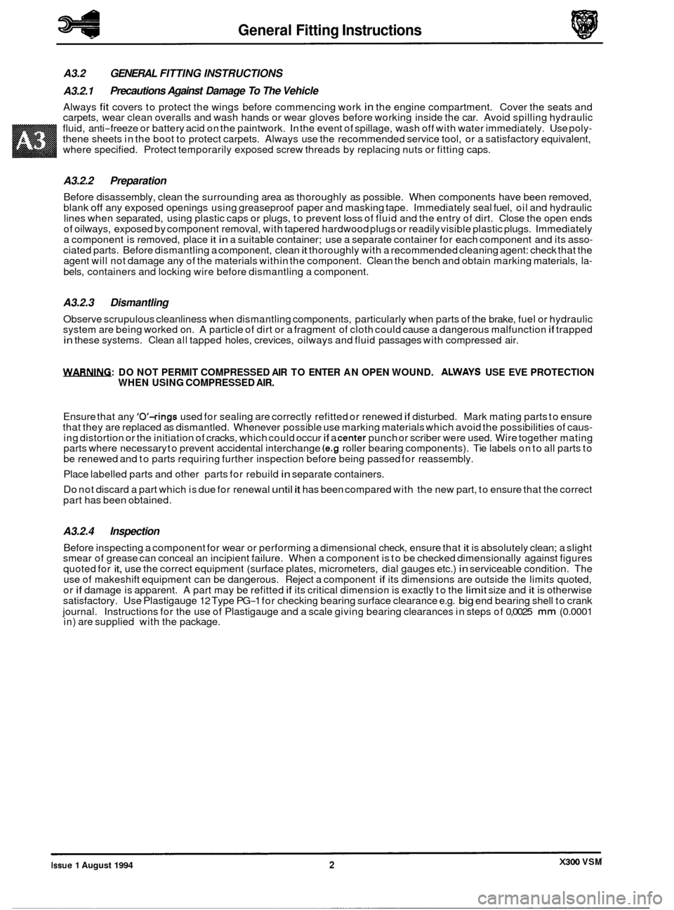
General Fitting Instructions
A3.2 GENERAL FITTING INSTRUCTIONS
A3.2.1
Always fit covers to protect the wings before commencing work in the engine compartment. Cover the seats and
carpets, wear clean overalls and wash hands or wear gloves before working inside the car. Avoid spilling hydraulic
fluid, anti
-freeze or battery acid on the paintwork. In the event of spillage, wash off with water immediately. Use poly- thene sheets in the boot to protect carpets. Always use the recommended service tool, or a satisfactory equivalent,
where specified. Protect temporarily exposed screw threads by replacing nuts or fitting caps.
Precautions Against Damage To The Vehicle
A3.2.2 Preparation
Before disassembly, clean the surrounding area as thoroughly as possible. When components have been removed,
blank off any exposed openings using greaseproof paper and masking tape. Immediately seal fuel, oil and hydraulic
lines when separated, using plastic caps or plugs, to prevent loss of fluid and the entry of dirt. Close the open ends
of oilways, exposed by component removal, with tapered hardwood plugs or readily visible plastic plugs. Immediately
a component is removed, place
it in a suitable container; use a separate container for each component and its asso- ciated parts. Before dismantling a component, clean it thoroughly with a recommended cleaning agent: check that the
agent will not damage any of the materials within the component. Clean the bench and obtain marking materials, la-
bels, containers and locking wire before dismantling a component.
A3.2.3 Dismantling
Observe scrupulous cleanliness when dismantling components, particularly when parts of the brake, fuel or hydraulic
system are being worked on. A particle of dirt or a fragment of cloth could cause a dangerous malfunction if trapped in these systems. Clean all tapped holes, crevices, oilways and fluid passages with compressed air.
WRNIFLG: DO NOT PERMIT COMPRESSED AIR TO ENTER AN OPEN WOUND. ALWAYS USE EVE PROTECTION
WHEN USING COMPRESSED AIR.
Ensure that any 'O'-rings used for sealing are correctly refitted or renewed if disturbed. Mark mating parts to ensure
that they are replaced as dismantled. Whenever possible use marking materials which avoid the possibilities of caus- ing distortion or the initiation of cracks, which could occur if a center punch or scriber were used. Wire together mating
parts where necessary to prevent accidental interchange (e.g roller bearing components). Tie labels on to all parts to
be renewed and to parts requiring further inspection before being passed for reassembly.
Place labelled parts and other parts for rebuild
in separate containers.
Do not discard a part which is due for renewal until it has been compared with the new part, to ensure that the correct
part has been obtained.
A3.2.4 Inspection
Before inspecting a component for wear or performing a dimensional check, ensure that it is absolutely clean; a slight
smear of grease can conceal an incipient failure. When a component is to be checked dimensionally against figures
quoted for
it, use the correct equipment (surface plates, micrometers, dial gauges etc.) in serviceable condition. The
use of makeshift equipment can be dangerous. Reject a component if its dimensions are outside the limits quoted,
or if damage is apparent. A part may be refitted if its critical dimension is exactly to the limit size and it is otherwise
satisfactory. Use Plastigauge 12 Type PG-1 for checking bearing surface clearance e.g. big end bearing shell to crank
journal. Instructions for the use of Plastigauge and a scale giving bearing clearances in steps of
0,0025 mm (0.0001
in) are supplied with the package.
0
0
0
X300 VSM Issue 1 August 1994 2
Page 486 of 521
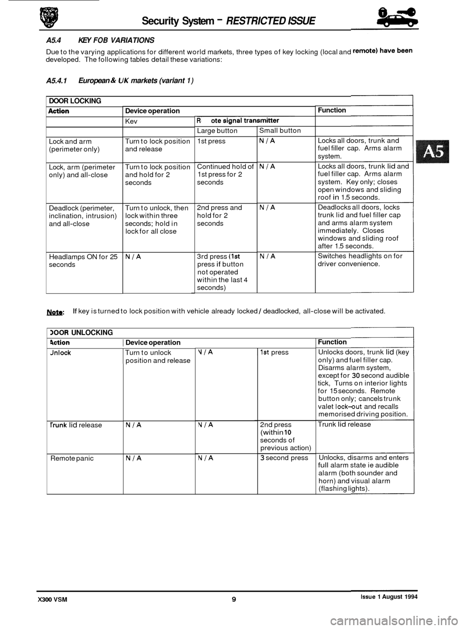
Jnlock Turn to unlock
position and release VIA I 1st press
Security System - RESTRICTED ISSUE
A5.4 KEY FOB VARIATIONS
Due to the varying applications for different world markets, three types of key locking (local and
developed. The following tables detail these variations:
A5.4.1 European & UK markets
(variant 1)
DOOR LOCKING
Function
Device operation
Remote signal transmitter
Kev -
Large button
1st press Small
button
Locks all doors, trunk and
fuel filler cap. Arms alarm
system.
Locks all doors, trunk
lid and
fuel filler cap. Arms alarm
system. Key only; closes
open windows and sliding
roof
in 1.5 seconds.
Deadlocks all doors, locks
trunk lid and fuel filler cap
and arms alarm system
immediately. Closes
windows and sliding roof
after 1.5 seconds.
Switches headlights on for
driver convenience.
Lock
and arm
(perimeter only)
NIA Turn to lock position
and release
Continued hold
of
1st press for 2
seconds NIA
NIA
Lock, arm (perimeter
only) and all
-close Turn
to lock position
and hold for 2
seconds
Deadlock (perimeter,
inclination, intrusion)
and all
-close Turn
to unlock, then
lock within three
seconds; hold in
lock for all close 2nd
press and
hold for 2
seconds
0
Headlamps ON for 25
seconds 3rd
press (1st
press if button
not operated
within the last
4
seconds)
NIA NIA
1ynfn: If key is turned to lock position with vehicle already locked / deadlocked, all-close will be activated.
BOOR UNLOCKING
Function
Unlocks doors, trunk lid (key
only) and fuel filler cap.
Disarms alarm system,
except for
30 second audible
tick, Turns on interior lights
for 15 seconds. Remote
button only; cancels trunk
valet
lock-out and recalls
memorised driving position.
Trunk
lid release
9ction I Device operation
0
0
NIA 2nd press
(within 10
seconds of
previous action)
NIA
NIA
rrunk lid release
Remote panic
NIA 3 second press Unlocks,
disarms and enters full alarm state ie audible
alarm (both sounder and
horn) and visual alarm
(flashing lights).
Issue 1 August 1994 X300 VSM 9