gearbox JAGUAR XJ6 1994 2.G Workshop Manual
[x] Cancel search | Manufacturer: JAGUAR, Model Year: 1994, Model line: XJ6, Model: JAGUAR XJ6 1994 2.GPages: 521, PDF Size: 17.35 MB
Page 8 of 521
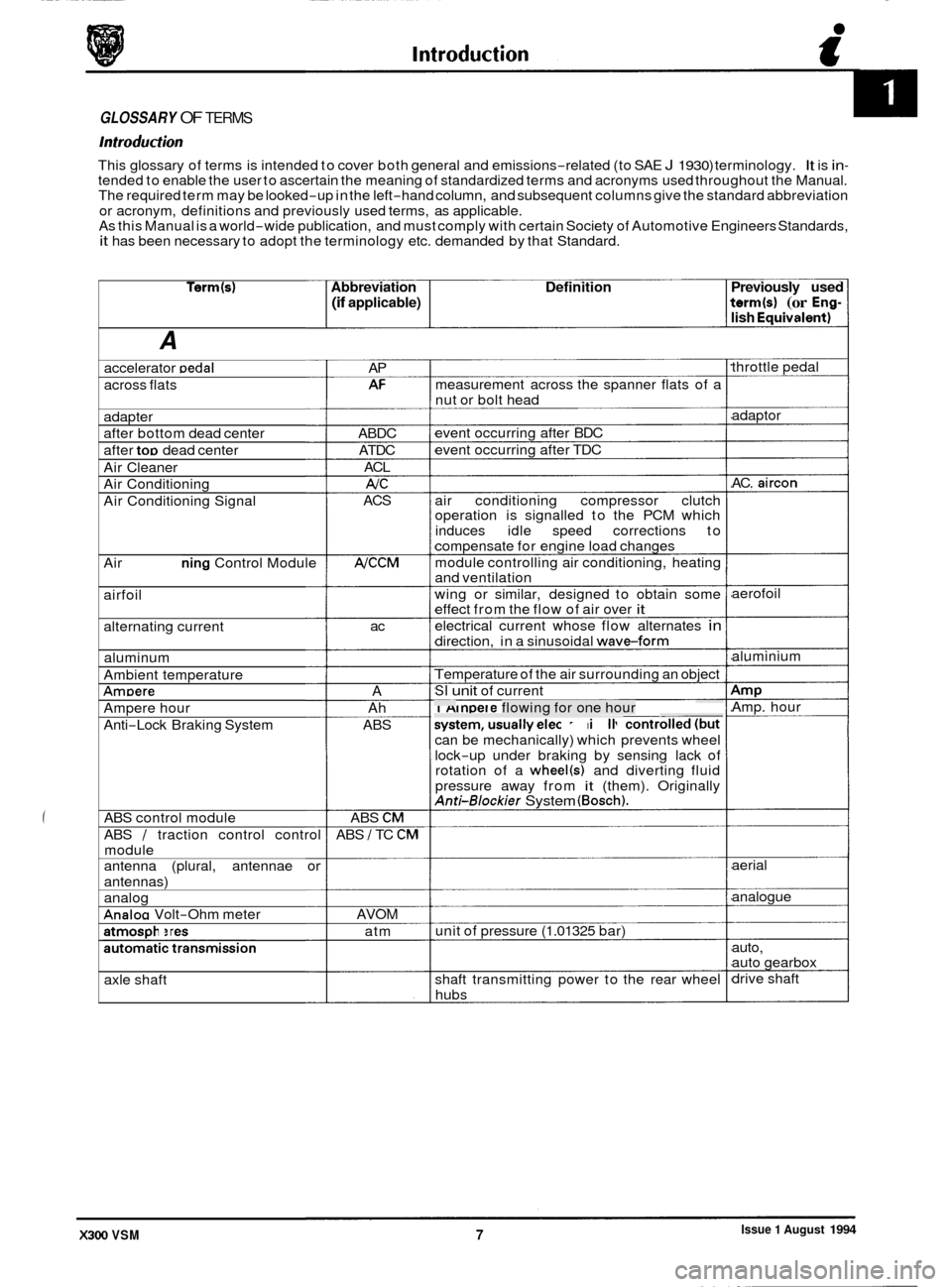
GLOSSARY OF TERMS
Introduction
This glossary of terms is intended to cover both general and emissions-related (to SAE J 1930) terminology. It is in- tended to enable the user to ascertain the meaning of standardized terms and acronyms used throughout the Manual.
The required term may be looked-up in the left-hand column, and subsequent columns give the standard abbreviation
or acronym, definitions and previously used terms, as applicable.
As this Manual is a world
-wide publication, and must comply with certain Society of Automotive Engineers Standards, it has been necessary to adopt the terminology etc. demanded by that Standard.
Term(s) Abbreviation Definition Previously used
(if applicable) term(s) (or Eng- lish Eauivalent)
A
throttle pedal
accelerator Dedal AP
AI= measurement across the spanner flats of a
across flats
nut or bolt head
adaptor
AC.
aircon
adapter
after bottom dead center
after
too dead center event
occurring after BDC
event occurring after TDC
ABDC
ATDC ACL
AIC
ACS
Air
Cleaner
Air Conditioning
Air Conditioning Signal air conditioning
compressor clutch
operation is signalled to the PCM which
induces idle speed corrections to
compensate for engine load changes
module controlling air conditioning, heating
and ventilation
wing or similar, designed to obtain some
effect from the flow of air over
it
electrical current whose flow alternates in
direction, in a sinusoidal waveform
NCCM Air Conditioning Control Module
airfoil aerofoil
alternating current ac
aluminium
aluminum
Ambient temperature Temperature
of the air surrounding an object
SI unit of current AmDere A Amp Amp. hour -~ 1 Ampere flowing for one hour
system, usually ele&o&ally controlled (but ~- __. .. . Ampere hour
Anti
-Lock Braking System Ah
ABS can be mechanically) which prevents wheel
lock
-up under braking by sensing lack of
rotation of a wheel(s) and diverting fluid
pressure away from
it (them). Originally Anti-Blockier System (Bosch).
ABS control module
ABS
/ traction control control
module ABS
CM
ABS I TC CM
aerial
antenna (plural, antennae or
antennas)
analog
Analoa Volt-Ohm meter analogue
AVOM unit of pressure
(1.01325 bar)
atmospheres
automatic transmission atm
auto,
auto gearbox
drive shaft
axle shaft shaft
transmitting power to the rear wheel
hubs
.-
Issue 1 August 1994 X300 VSM 7
Page 20 of 521
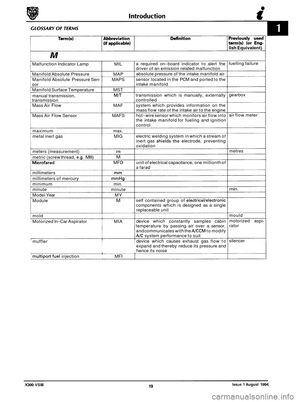
- .. I lish Equivalent)
M
Malfunction Indicator Lamp MIL
Manifold Absolute Pressure MAP
Manifold Absolute Pressure Sen
- MAPS
sor
Manifold Surface Temperature MST
manual transmission,
M/T transmission
Mass Air Flow MAF
Mass Air Flow Sensor MAFS
maximum max.
metal inert gas MIG ~
meters (measurement) m
metric
(screw thread, e.g. M8) M
MFD I Microfarad
millimeters mm
millimeters
of mercury mmHg
minimum min.
minute minute
Model Year MY
Module
M
mold
Motorized In
-Car Aspirator MIA
muffler
multiport fuel injection MFI a required
on
-board indicator to alert the
driver of an emission related malfunction
absolute pressure of the intake manifold air
sensor located in the PCM and ported to the
intake manifold
transmission which is manually, externally
controlled
system which provides information on the
mass flow rate of the intake air to the engine
hot
-wire sensor which monitors air flow into
the intake manifold for fueling and ignition
control
electric welding system in which a stream of
inert gas
shielbs~the electrode, preventing
oxidation
unit of electrical capacitance, one millionth of
a farad
self contained group of electrical/electronic
components which is designed as a single
replaceable unit
device which constantly samples cabin
temperature by passing air over a sensor,
and communicates with the
NCCM to modify
NC system performance to suit
device which causes exhaust gas flow to
expand and thereby reduce its pressure and
hence its noise fuelling failure
gearbox
air flow meter
metres
min.
mould
motorized aspi
-
rator
silencer ~~
X300 VSM 19 Issue 1 August 1994
Page 22 of 521
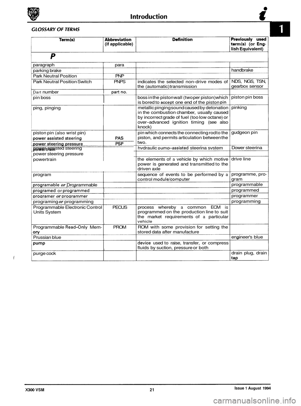
(if applicable) term(s) (or Eng-
lish Equivalent)
paragraph para
parking brake
Park Neutral Position PNP
Park Neutral Position Switch PNPS
Dart number I Dartno.
I pin boss
ping, pinging
piston pin
(also wrist pin)
power assisted steering
power steering pressure
. powertrain
program
Droaramable or Droarammable I
Droaramed or Droarammed I
Droaramer or Droarammer I
programing or programming
Programmable Electronic Control
I PECUS
Units System
I Programmable Read-only Mem- I PROM
on/ Prussian blue
Pump
purge cock I
indicates the selected non-drive modes of
the (automatic) transmission
boss in the piston wall (two per piston) which
is bored to
accept one end of the piston pin
metallic pinging sound caused by detonation
in the combustion chamber, usually caused
by incorrect grade of fuel (too low octane) or
over
-advanced ignition timing (see also knock)
pin which connects the connecting rod to the
piston, and permits articulation between the
two.
hvdraulic
DumD-assisted steerina svstem
the elements of
a vehicle by which motive
power is generated and transmitted to the
driven axle
sequence of events to be performed by
a
control module/comDuter
process whereby a common ECM is programmed on the production line to suit
the market requirements of
a particular vehicle
ROM with some provision for setting the
stored data after manufacture
device used to raise, transfer, or compress
fluids by suction, pressure or both handbrake
NDS, NGS, TSN,
gearbox sensor
piston pin boss
pinking
gudgeon pin
Dower steerina
drive line
programme, pro
-
gram
programmable
programmed
programmer
programming
enaineer's blue
drain plug, drain
tap
Issue 1 August 1994 X300 VSM 21
Page 49 of 521
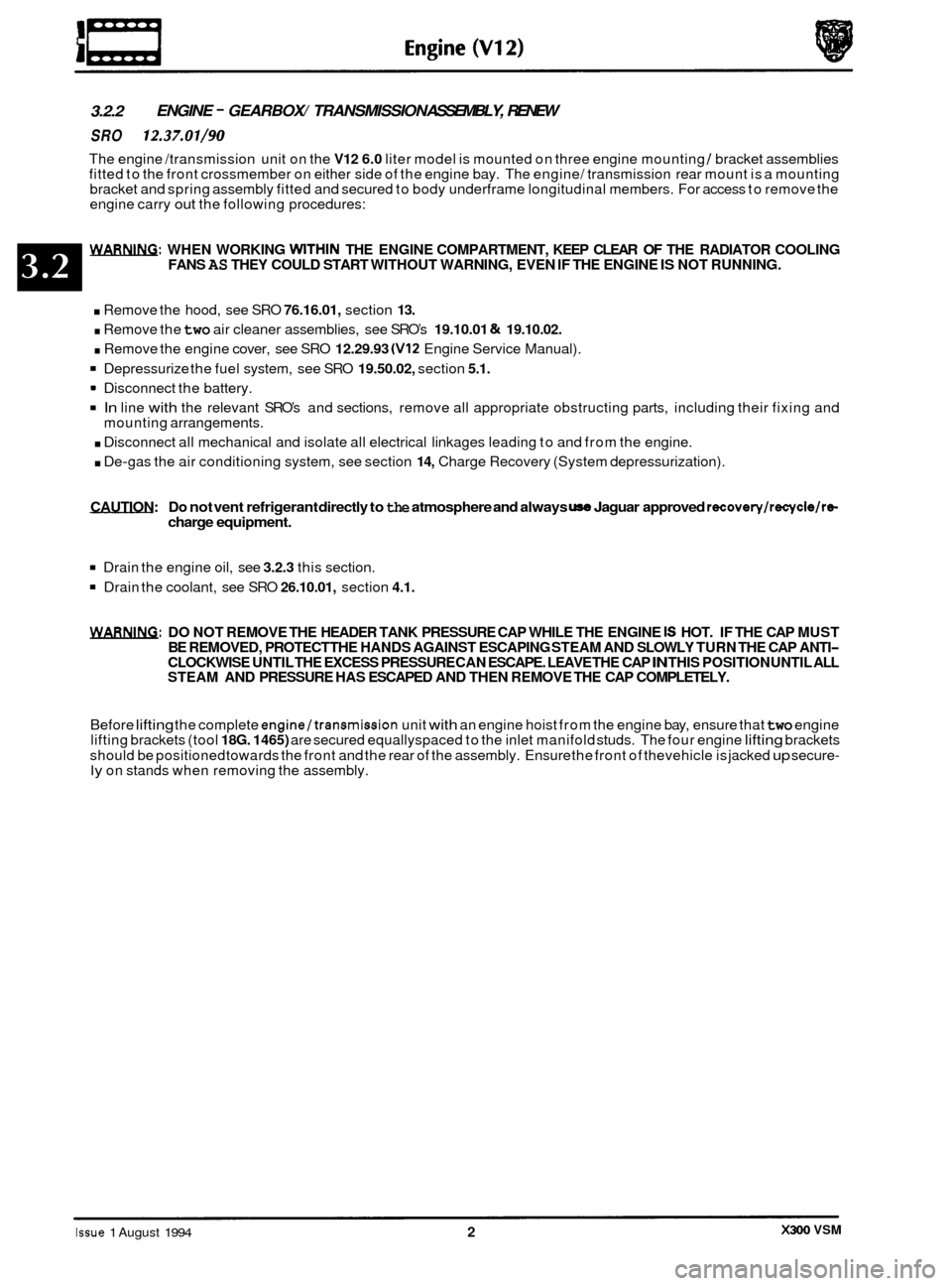
3.2.2 ENGINE - GEARBOX/ TRANSMISSION
ASSEMBLY, RENEW
SRO 12.37.01/90
The engine /transmission unit on the V12 6.0 liter model is mounted on three engine mounting / bracket assemblies
fitted to the front crossmember on either side of the engine bay. The engine/ transmission rear mount is a mounting
bracket and spring assembly fitted and secured to body underframe longitudinal members. For access to remove the
engine carry
out the following procedures:
WARNING: WHEN WORKING WITHIN THE ENGINE COMPARTMENT, KEEP CLEAR OF THE RADIATOR COOLING
FANS AS THEY COULD START WITHOUT WARNING, EVEN IF THE ENGINE IS NOT RUNNING.
. Remove the hood, see SRO 76.16.01, section 13.
. Remove the two air cleaner assemblies, see SRO’s 19.10.01 & 19.10.02.
. Remove the engine cover, see SRO 12.29.93 (V12 Engine Service Manual).
Depressurize the fuel system, see SRO 19.50.02, section 5.1.
In line with the relevant SRO’s and sections, remove all appropriate obstructing parts, including their fixing and
. Disconnect all mechanical and isolate all electrical linkages leading to and from the engine.
. De-gas the air conditioning system, see section 14, Charge Recovery (System depressurization).
Disconnect
the battery.
mounting arrangements.
CAUTION: Do
not vent refrigerant directly to the atmosphere and always use Jaguar approved recovery/recycle/ra charge equipment.
Drain the engine oil, see 3.2.3 this section.
Drain the coolant, see SRO 26.10.01, section 4.1.
WARNING: DO NOT REMOVE THE HEADER TANK PRESSURE CAP WHILE THE ENGINE IS HOT. IF THE CAP MUST
BE REMOVED, PROTECT THE HANDS AGAINST ESCAPING STEAM AND SLOWLY TURN THE CAP ANTI- CLOCKWISE UNTIL THE EXCESS PRESSURE CAN ESCAPE. LEAVE THE CAP IN THIS POSITION UNTIL ALL
STEAM AND PRESSURE HAS ESCAPED AND THEN REMOVE THE CAP COMPLETELY.
Before
lifting the complete engine/transmission unit with an engine hoist from the engine bay, ensure that two engine
lifting brackets (tool 18G. 1465) are secured equallyspaced to the inlet manifold studs. The four engine lifting brackets
should be positioned towards the front and the rear of the assembly. Ensure the front of thevehicle is jacked
up secure- ly on stands when removing the assembly.
X300 VSM Issue 1 August 1994 2
Page 183 of 521
-5 Driveshafts & Final Drive
0
Fixing
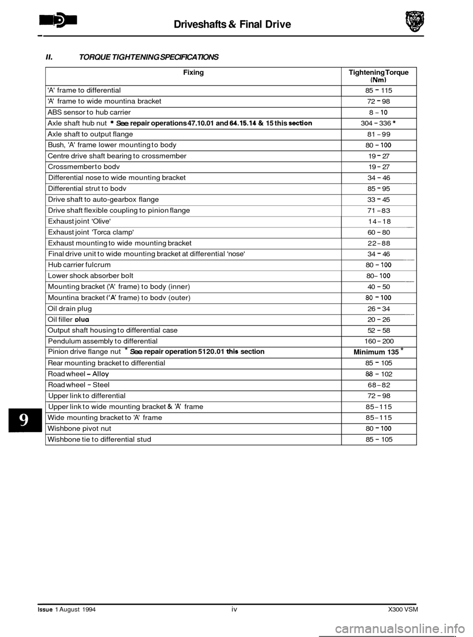
11. TORQUE TIGHTENING SPECIFICATIONS
Tightening Torque
(Nm)
'A' frame to differential 85 - 115
'A' frame to wide mountina bracket 72 - 98
ABS sensor to hub carrier
Axle shaft hub nut
* See repair operations 47.10.01 and 64.15.14 & 15 this don
8- 10
304 - 336 *
Axle shaft to output flange
Bush,
'A' frame lower mounting to body
81 -99
80
- 100
Centre drive shaft bearing to crossmember 19 - 27
Crossmember to bodv 19 - 27
Differential nose to wide mounting bracket - 34 - 46
Issue 1 August 1994 iv X300 VSM
Differential strut to bodv 85 - 95
Drive shaft to auto-gearbox flange
Drive shaft flexible coupling to pinion flange 33 - 45
71
-83
Exhaust joint 'Olive'
Exhaust joint 'Torca clamp' -. 14-18
60
- 80
Exhaust mounting to wide mounting bracket
Final drive unit to wide mounting bracket at differential 'nose'
Hub carrier fulcrum 22-88
34
- 46
80
- 100 ___
Lower shock absorber bolt
Mounting bracket
('A' frame) to body (inner)
Mountina bracket
('A' frame) to bodv (outer)
- 80- 100
40 - 50
80 - 100
Oil drain plug __ 26 - 34
Oil filler DIU~ 20 - 26
Output shaft housing to differential case
Pendulum assembly to differential
Pinion drive flange nut
* See repair operation 5120.01 this section
Road wheel -Alloy
Road wheel - Steel
Upper link to differential
Rear
mounting bracket to differential
52 - 58
160
- 200
Minimum 135 *
85 - 105
88 - 102
68
-82
72
- 98 ~~~~~
Upper
link to wide mounting bracket & 'A' frame
Wide mounting bracket to
'A' frame
85-115
85
-115
Wishbone pivot nut
Wishbone tie to differential stud 80 - 100
85 - 105
Page 186 of 521
Driveshafts & Final Drive
9.1 MAJOR COMPONENT DESCRIPTION
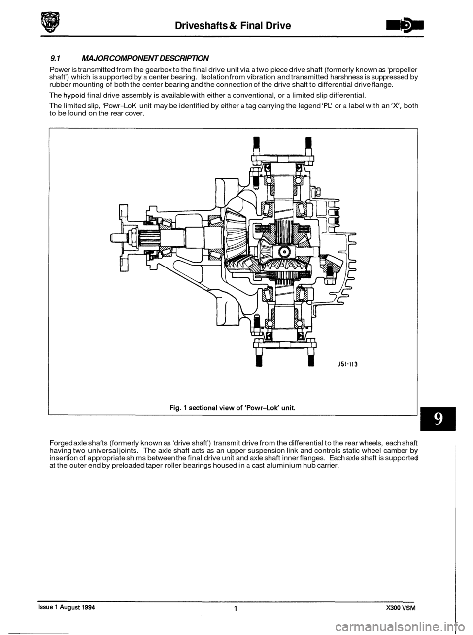
Power is transmitted from the gearbox to the final drive unit via a two piece drive shaft (formerly known as ‘propeller
shaft’) which is supported by a center bearing. Isolation from vibration and transmitted harshness is suppressed by
rubber mounting of both the center bearing and the connection of the drive shaft to differential drive flange.
The
hypoid final drive assembly is available with either a conventional, or a limited slip differential.
The limited slip, ‘Powr
-LoK unit may be identified by either a tag carrying the legend ’PC or a label with an ‘X, both
to be found on the rear cover.
U
Forged axle shafts (formerly known as ‘drive shaft’) transmit drive from the differential to the rear wheels, each shaft
having two universal joints. The axle shaft acts as an upper suspension link and controls static wheel camber by insertion of appropriate shims between the final drive unit and axle shaft inner flanges. Each axle shaft is supported
at the outer end by preloaded taper roller bearings housed in a cast aluminium hub carrier.
Page 187 of 521
Driveshafts & Final Drive
9.2 DRIVE SHAm, ALIGN
SRO 47.15.51
CAUTION: To preserve 'drive line' refinement, individual parts, other than fixings, MUST NOT be renewed. In the
event of any balance or drive shaft component related problem, the complete assembly must be renewed.
Under no circumstances must the flexible coupling (or its fixings) be loosened or removed from the drive
shaft flange.
Preliminary Checks
Before this procedure is actioned it is advisable to ensure that:
The gearbox mounting center stud is positioned centrally in relation to the crossmember inspection hole.
The crossmember is central on the body fixings and not 'hard over' to one side.
The differential spigot radial
run-out is within specification, see preliminary pages.
If the vehicle has been standing for
a period the tires may be 'flat-spotted'. If so, this will clear in approximate.;
400 km (250 miles). After this distance the source of vibration should be reassessed.
12 Cylinder
8 Remove exhaust center section.
All
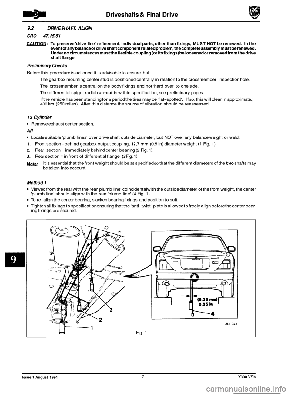
8 Locate suitable 'plumb lines' over drive shaft outside diameter, but NOT over any balance weight or weld:
1.
2.
3.
l\lnfe:
Front section -behind gearbox output coupling, 12,7 mm (0.5 in) diameter weight (1 Fig. 1).
Rear section - immediately behind center bearing (2 Fig. 1).
Rear section - in front of differential flange (3 Fig. 1)
It is essential that the front weight should be as specified so that the different diameters of the two shafts may
be taken into account.
Method 1
8 Viewed from the rear with the rear 'plumb line' coincidental with the outside diameter of the front weight, the center
8 To re-align the center bearing, slacken bearing fixings and position to suit.
8 Tighten all fixings to specification ensuring that the 'anti-twist' plate is allowed to freely align before the center bear-
'plumb line' should align with the rear 'plumb line' (4 Fig. 1).
ing fixings are secured.
Fig. 1
1
JL7 OL3
0
0
0
0 ~~~~
Issue 1 August 1994 2 X300 VSM
Page 200 of 521
10.1 STEERING SYSTEM DESCRIPTION
10.1.1 Steering Column Major Components
Integrated column assembly incorporating power, or manual, reach /tilt mechanism and lock.
Ignition switch.
Ignition interlock solenoid.
Key transponder coil.
Body attachment points.
Depending upon model, the steering column may be adjusted for
tilt and reach, either by electrical or manual means.
Power variants may be either automatically or manually adjusted and all types have the entry / exit feature.
10.1.2 Steering Column Operating Principle
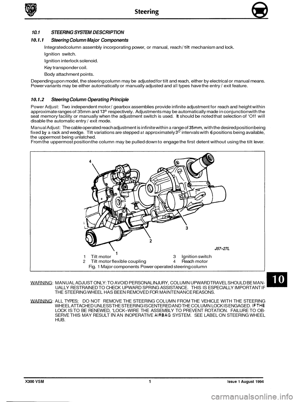
Power Adjust: Two independent motor / gearbox assemblies provide infinite adjustment for reach and height within
approximate ranges of 35mm and
13O respectively. Adjustments may be automatically made in conjunction with the
seat memory facility or manually when the adjustment switch is used. It should be noted that selection of 'Off will
disable the automatic entry / exit mode.
Manual Adjust: The cable operated reach adjustment is infinite within a range of 35mm, with the desired position being
fixed
by a rack and wedge. Tilt variations are stepped at approximately 3O intervals with 6 positions being available,
the uppermost being unlatched.
From the uppermost position the column may be pulled down to engage the first detent without using the
tilt lever.
WARNING: MANUAL ADJUST ONLY: TO AVOID PERSONAL INJURY, COLUMN UPWARD TRAVEL SHOULD BE MAN- UALLY RESTRAINED TO CHECK UPWARD SPRING ASSISTANCE. THIS IS ESPECIALLY IMPORTANT IF
THE STEERING WHEEL HAS BEEN REMOVED FOR MAINTENANCE REASONS.
WARNING: ALL TYPES; DO NOT REMOVE THE STEERING COLUMN FROM THE VEHICLE WITH THE STEERING
WHEEL ATTACHED UNLESS THE STEERING
IS CENTERED AND THE COLUMN LOCK IS ENGAGED. IFTHE
SERVE THIS MAY RESULT IN AN INOPERATIVE AIRBAG SYSTEM. SEE LABEL ON STEERING WHEEL
HUB. LOCK IS TO BE RENEWED, 'LOCK-WIRE THE ASSEMBLY TO PREVENT ROTATION. FAILURE TO OB-
0
X300 VSM 1 Issue 1 August 1994
J57-27L
3 Ignition switch 1 1 Tilt motor 2 Tilt motor flexible coupling 4 Reach motor
Fig.
1 Major components Power operated steering column
Page 276 of 521
Body Components & Trim ~
issue 1 August 1994 X300 VSM 21
13.3.17 Fascia Board, Renew
SRO 76.46.01
. Remove
the battery cover and disconnect the battery.
Remove the drivers side and passenger side underscuttle
pads, see sub
-sections 13.3.19 and 13.3.20.
. Remove the drivers airbag module, see section 15.5.
Remove the steering wheel, section 10.
Remove the drivers side and passenger side fascia closing
. Remove the fascia center veneer panel, see subsection
Remove the fascia board for access, see subsection
. Disconnect the air conditioning differential potentiometer
Remove the differential potentiometer assembly.
. Displace and reposition the through panel connectors
from the fascia assembly.
. Displace the fascia vent motor / gearbox assemblies har- ness multi-plug from the mounting bracket.
. Disconnect and reposition the fascia harness to console
harness
multi-plug from the mounting bracket.
. Disconnect the BPU harness multi-plugs.
Remove the tiestraps securing the harness to the fascia.
. Reposition the fascia on a bench.
= Displace and reposition the solar sensor assembly from
Disconnect the solar sensor harness multi-plug.
Remove the solar sensor assembly.
= Undo and remove the defrost vents securing screws.
Displace and reposition the defrost vent assemblies.
. Disconnect the tweeter speaker harness multi-plugs.
. Remove the defrost vent assemblies.
. Displace the fascia harness grommet from the fascia.
. Route the harness through the aperture.
Remove the fascia harness assembly.
. Undo and remove passenger airbag deployment door to
fascia securing bolts ( one bolt is removed with the fascia).
. Displace and remove the deployment door assembly.
. Undo and remove the passenger airbag module to fascia
. Displace and remove the airbag module assembly.
. Undo and remove the airbag module I BPU mounting
bracket assembly to fascia securing nuts 1 bolts.
= Displace and remove the mounting bracket assembly.
. Retrieve the spacing washers.
. Displace and remove the side vent outlets from the fascia.
. Displace and remove the side vent ducts securing clips.
. Displace and remove the side vent ducts.
. Undo and remove the center vent flap assembly to fascia
. Displace and remove the center vent flap assembly.
Undo and remove fascia location bracket securing nuts.
Displace and remove the location bracket.
panels, see
sub
-sections 13.3.22 and 13.3.21.
13.3.23. 13.3.17.
harness multi
-plug.
the fascia.
securing bolts.
securing nuts.
Page 277 of 521
Body Components & Trim -
. Undo and remove the defrost vents clip location bracket
9 Displace and remove the clip location brackets.
Remove the defrost vent spire clips from the fascia.
Place the fascia aside.
. Place a new fascia on the bench.
. Fit and fully seat the defrost vent spire clips.
. Fit and align the defrost vent clip location brackets.
Fit and tighten the location brackets securing screws.
. Fit and align the fascia location brackets to the fascia.
. Fit and align the location bracket securing nuts.
. Fit and align the center vent flap assembly.
. Fit and tighten the flap assembly securing nuts.
. Fit and align the side vent ducts to the fascia assembly.
. Fit and fully seat the side vent ducts securing clips.
Fit and fully seat the side vent outlets to the fascia.
Fit and align the airbag module/BPU mounting bracket as-
. Fit and tighten the airbag module/ BPU mounting bracket
. Fit and align the airbag module to the fascia.
. Fit and tighten the airbag module securing bolts.
. Fit and align the airbag deployment door assembly to the
. Fit but do not fully tighten the door securing bolts.
. Align the door assembly to the fascia.
. Finally tighten the door securing bolts.
. Position the harness. Route the harness speaker / solar
sensor multi-plugs through the aperture in the fascia.
. Fully seat the harness grommet to the fascia aperture.
. Route the tweeter speaker harnesses along the defrost
vent aperture.
. Place the defrost vent assemblies to the fascia.
. Connect the speaker harness multi-plugs to the speakers.
Reposition and fit the vent assemblies to the fascia.
. Fit and tighten the vent securing screws.
Place the solar sensor assembly to the fascia.
. Reconnect the solar sensor harness multi-plug.
. Fully seat the solar sensor assembly to the fascia.
. Reposition the fascia assembly on the bench.
. Secure the harness to the fascia assembly using tiestraps.
. Reconnect the BPU harness multi-plugs.
. Reposition and fit the fascia harness to console harness
. Reconnect the fascia vent motor/gearboxassemblies har-
securing screws.
sembly and align the spacers.
securing nuts
/ bolts.
fascia.
multi
-plug to the mounting bracket.
ness
multi-plug.
X300 VSM Issue 1 August 1994 22