JEEP CHEROKEE 1988 Service Repair Manual
Manufacturer: JEEP, Model Year: 1988, Model line: CHEROKEE, Model: JEEP CHEROKEE 1988Pages: 1378, PDF Size: 19.9 MB
Page 851 of 1378
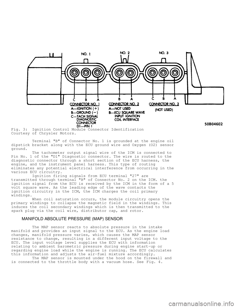
Fig. 3: Ignition Control Module Connector Identification
Courtesy of Chrysler Motors.
Terminal "B" of Connector No. 1 is grounded at the engine oil
dipstick bracket along with the ECU ground wire and Oxygen (O2) sensor\
ground.
The tachometer output signal wire of the ICM is connected to
Pin No. 1 of the "D1" Diagnostic connector. The wire is routed to the
diagnostic connector through a short section of the ECU harness, the
engine, and the instrument panel harness. This type of routing
eliminates any potential electrical interference from occurring in the
various ECU circuitry.
Ignition firing signals from ECU terminal "27" are
transmitted through terminal "B" of Connector No. 2 on the ICM. the
ignition signal from the ECU is received by the ICM in the form of a 5
volt square wave. As the leading edge of the wave contacts the
ignition circuitry in the ICM, the ICM charges the coil primary
windings.
When coil saturation occurs, the module circuitry opens the
primary windings to collapse the magnetic field in the windings. This
induces the coil secondary windings which is then transmitted to the
spark plug via the coil wire, distributor cap, and rotor.
MANIFOLD ABSOLUTE PRESSURE (MAP) SENSOR
The MAP sensor reacts to absolute pressure in the intake
manifold and provides an input signal to the ECU. As the engine load
changes, manifold pressure varies, which causes the MAP sensor
resistance to change, resulting in a different input voltage to the
ECU. The input voltage level supplies the ECU with information
relating to ambient barometric pressure during engine start-up or
regarding engine load while the engine is running. The ECU calculates
this information and adjusts the air-fuel mixture accordingly.
The MAP sensor is mounted under the hood on the firewall and
is connected to the throttle body with a vacuum hose. See Fig. 4.
Page 852 of 1378
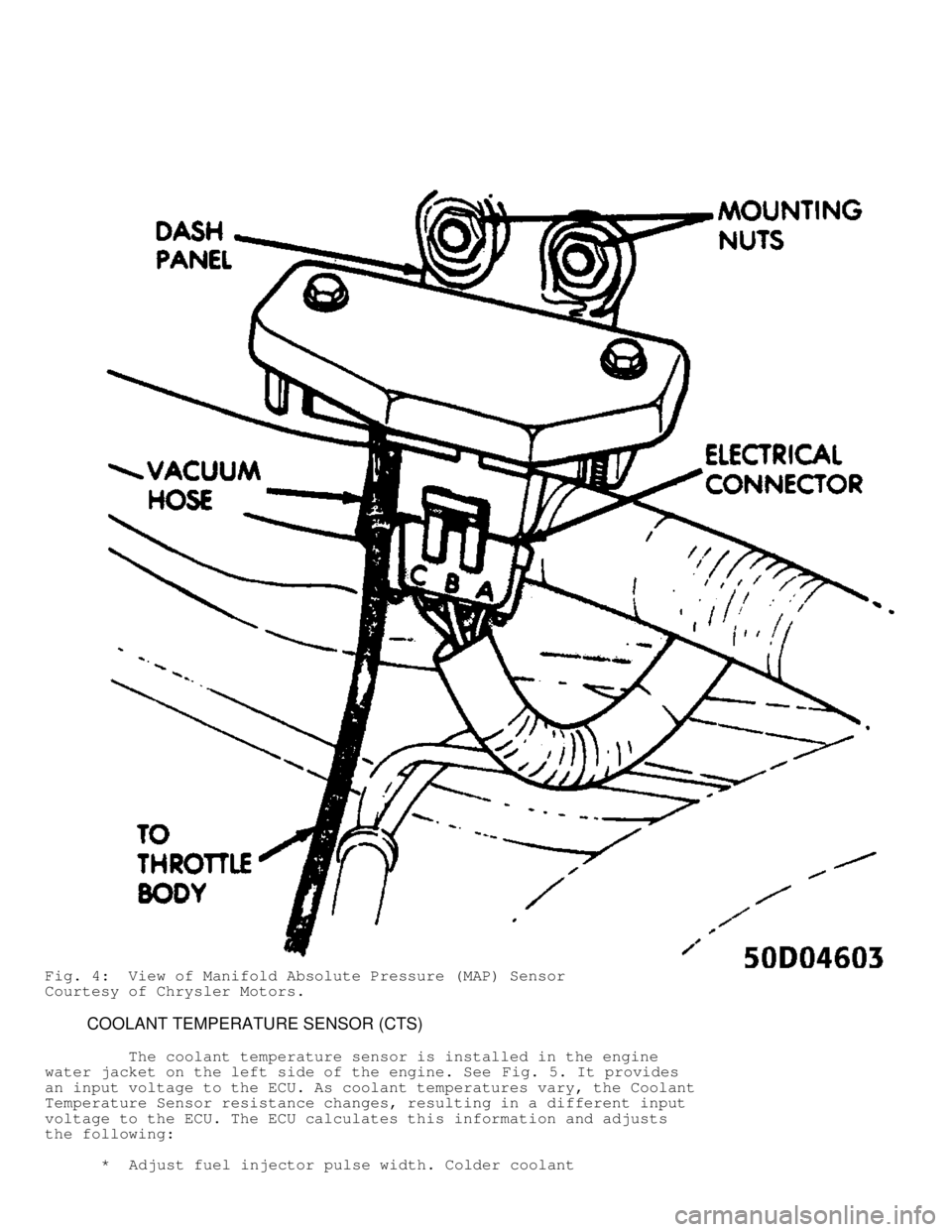
Fig. 4: View of Manifold Absolute Pressure (MAP) Sensor
Courtesy of Chrysler Motors.
COOLANT TEMPERATURE SENSOR (CTS)
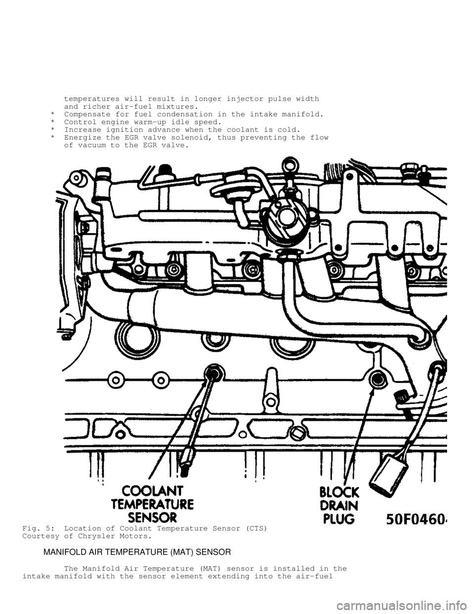
The coolant temperature sensor is installed in the engine
water jacket on the left side of the engine. See Fig. 5. It provides
an input voltage to the ECU. As coolant temperatures vary, the Coolant
Temperature Sensor resistance changes, resulting in a different input
voltage to the ECU. The ECU calculates this information and adjusts
the following:
* Adjust fuel injector pulse width. Colder coolant
Page 853 of 1378
temperatures will result in longer injector pulse width
and richer air-fuel mixtures.
* Compensate for fuel condensation in the intake manifold.
* Control engine warm-up idle speed.
* Increase ignition advance when the coolant is cold.
* Energize the EGR valve solenoid, thus preventing the flow
of vacuum to the EGR valve.
Fig. 5: Location of Coolant Temperature Sensor (CTS)
Courtesy of Chrysler Motors.
MANIFOLD AIR TEMPERATURE (MAT) SENSOR
The Manifold Air Temperature (MAT) sensor is installed in the\
intake manifold with the sensor element extending into the air-fuel
Page 854 of 1378
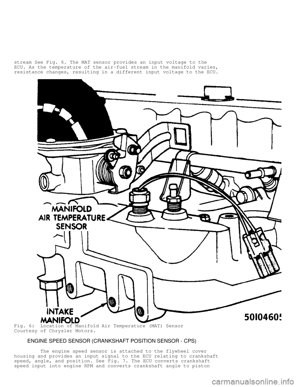
stream See Fig. 6. The MAT sensor provides an input voltage to the
ECU. As the temperature of the air-fuel stream in the manifold varies,
resistance changes, resulting in a different input voltage to the ECU.
Fig. 6: Location of Manifold Air Temperature (MAT) Sensor
Courtesy of Chrysler Motors.
ENGINE SPEED SENSOR (CRANKSHAFT POSITION SENSOR - CPS)
The engine speed sensor is attached to the flywheel cover
housing and provides an input signal to the ECU relating to crankshaft
speed, angle, and position. See Fig. 7. The ECU converts crankshaft
speed input into engine RPM and converts crankshaft angle to piston
Page 855 of 1378
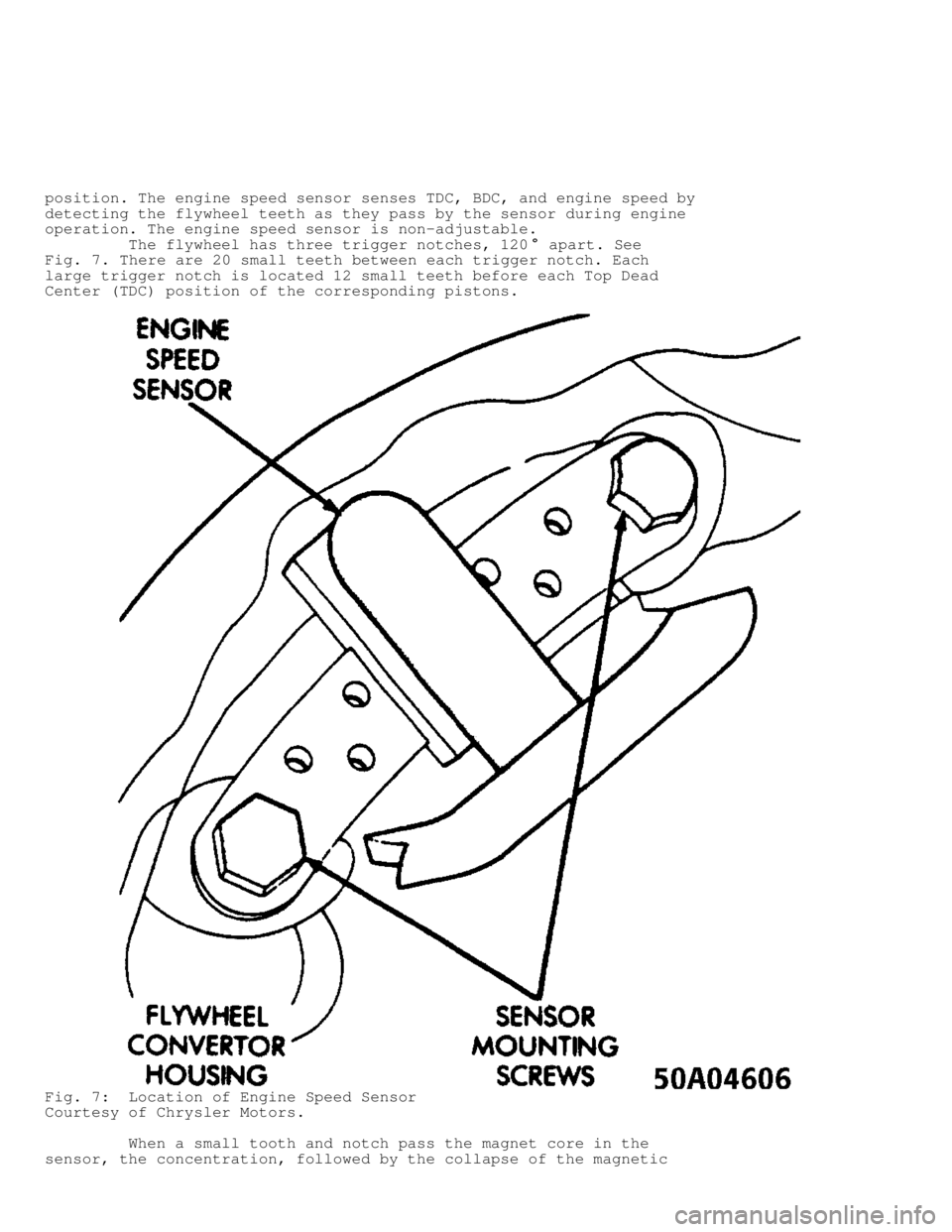
position. The engine speed sensor senses TDC, BDC, and engine speed by
detecting the flywheel teeth as they pass by the sensor during engine
operation. The engine speed sensor is non-adjustable.
The flywheel has three trigger notches, 120
� apart. See
Fig. 7 . There are 20 small teeth between each trigger notch. Each
large trigger notch is located 12 small teeth before each Top Dead
Center (TDC) position of the corresponding pistons.
Fig. 7: Location of Engine Speed Sensor
Courtesy of Chrysler Motors.
When a small tooth and notch pass the magnet core in the
sensor, the concentration, followed by the collapse of the magnetic
Page 856 of 1378
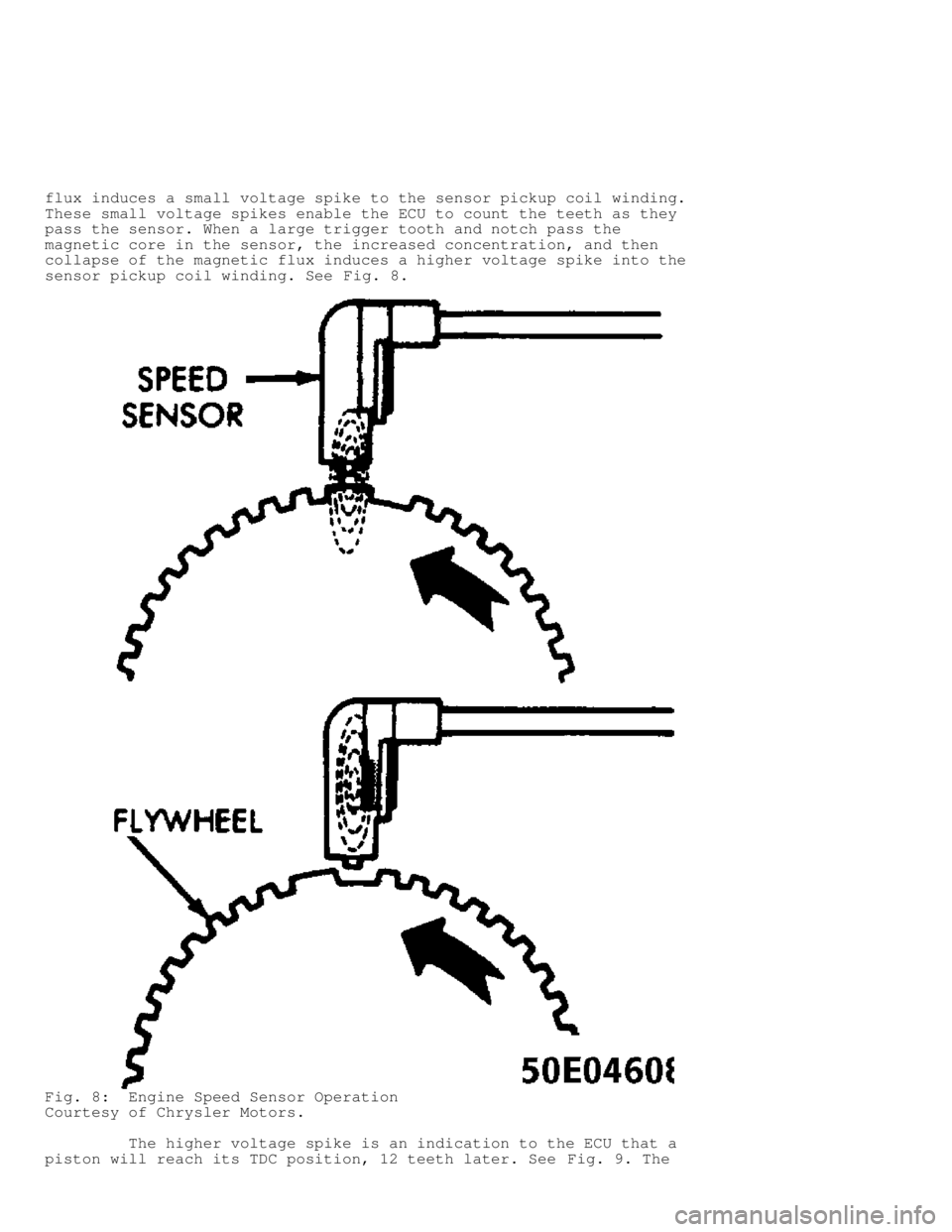
flux induces a small voltage spike to the sensor pickup coil winding.
These small voltage spikes enable the ECU to count the teeth as they
pass the sensor. When a large trigger tooth and notch pass the
magnetic core in the sensor, the increased concentration, and then
collapse of the magnetic flux induces a higher voltage spike into the
sensor pickup coil winding. See Fig. 8.
Fig. 8: Engine Speed Sensor Operation
Courtesy of Chrysler Motors.
The higher voltage spike is an indication to the ECU that a
piston will reach its TDC position, 12 teeth later. See Fig. 9. The
Page 857 of 1378
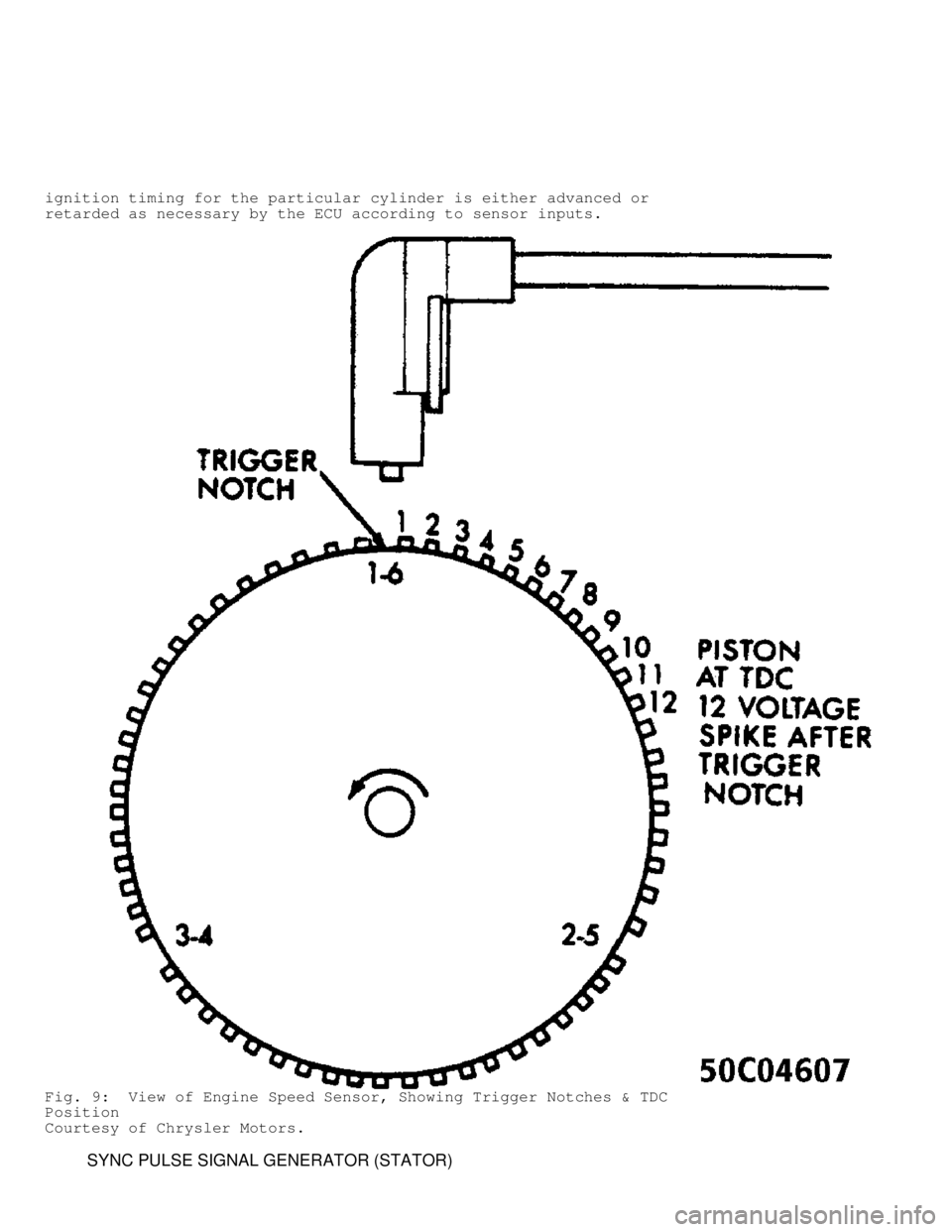
ignition timing for the particular cylinder is either advanced or
retarded as necessary by the ECU according to sensor inputs.
Fig. 9: View of Engine Speed Sensor, Showing Trigger Notches & TDC
Position
Courtesy of Chrysler Motors.
SYNC PULSE SIGNAL GENERATOR (STATOR)
Page 858 of 1378
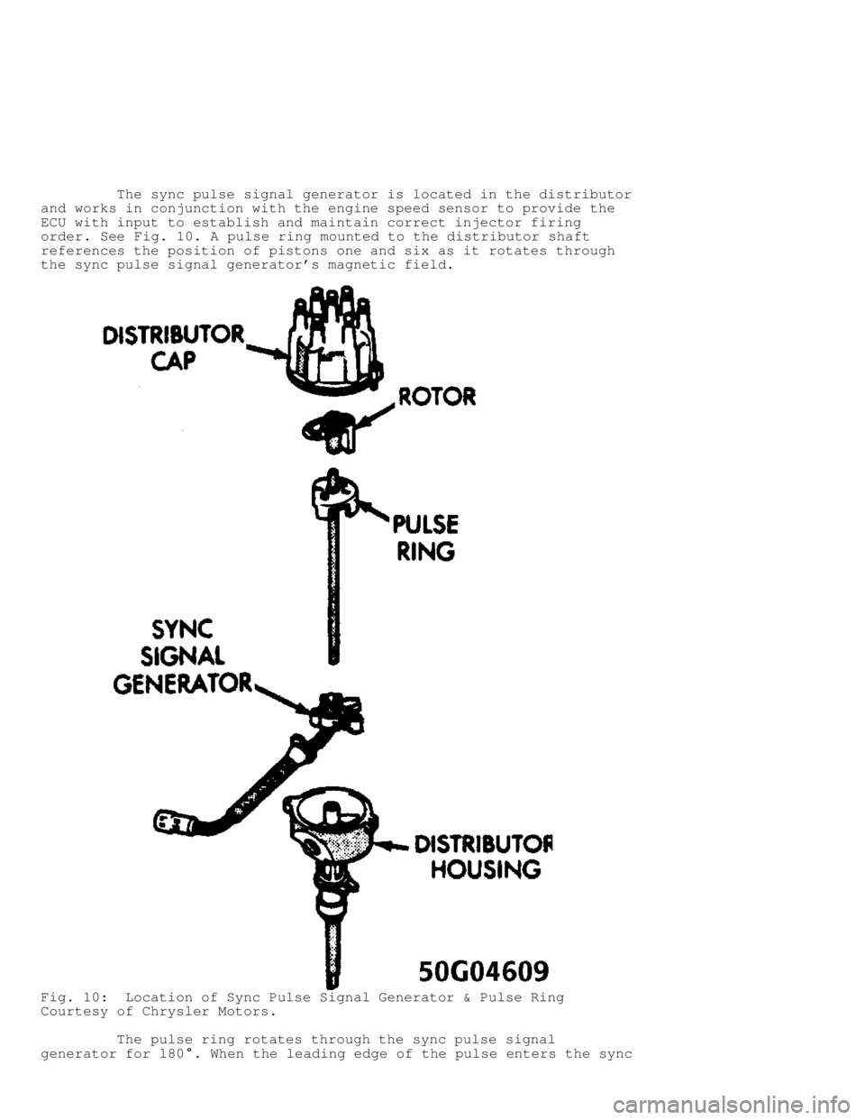
The sync pulse signal generator is located in the distributor
and works in conjunction with the engine speed sensor to provide the
ECU with input to establish and maintain correct injector firing
order. See Fig. 10. A pulse ring mounted to the distributor shaft
references the position of pistons one and six as it rotates through
the sync pulse signal generator's magnetic field.
Fig. 10: Location of Sync Pulse Signal Generator & Pulse Ring
Courtesy of Chrysler Motors.
The pulse ring rotates through the sync pulse signal
generator for l80
�. When the leading edge of the pulse enters the sync
Page 859 of 1378
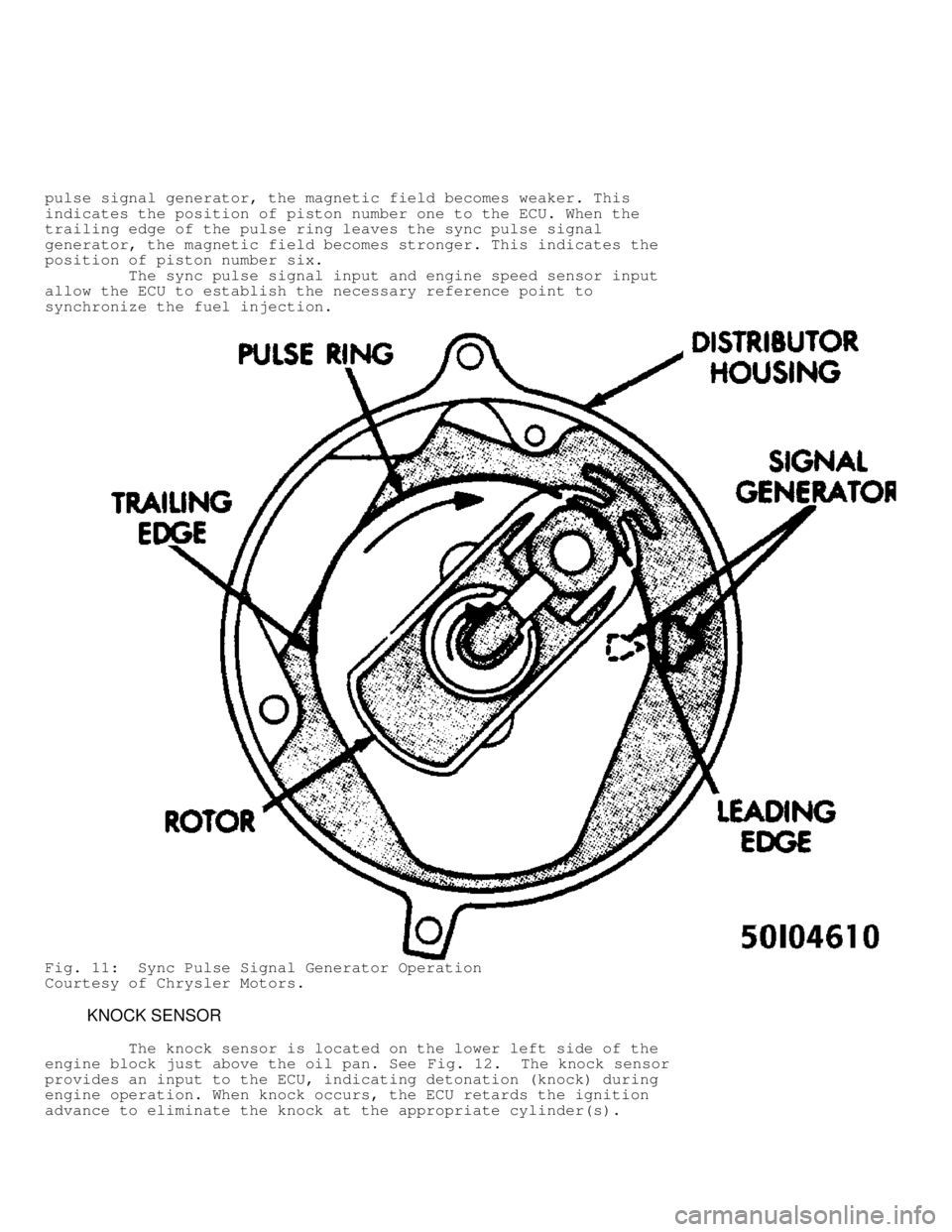
pulse signal generator, the magnetic field becomes weaker. This
indicates the position of piston number one to the ECU. When the
trailing edge of the pulse ring leaves the sync pulse signal
generator, the magnetic field becomes stronger. This indicates the
position of piston number six.
The sync pulse signal input and engine speed sensor input
allow the ECU to establish the necessary reference point to
synchronize the fuel injection.
Fig. 11: Sync Pulse Signal Generator Operation
Courtesy of Chrysler Motors.
KNOCK SENSOR
The knock sensor is located on the lower left side of the
engine block just above the oil pan. See Fig. 12. The knock sensor
provides an input to the ECU, indicating detonation (knock) during
engine operation. When knock occurs, the ECU retards the ignition
advance to eliminate the knock at the appropriate cylinder(s).
Page 860 of 1378
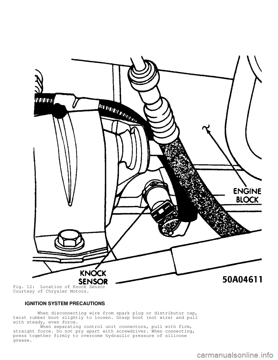
Fig. 12: Location of Knock Sensor
Courtesy of Chrysler Motors.
IGNITION SYSTEM PRECAUTIONS
When disconnecting wire from spark plug or distributor cap,
twist rubber boot slightly to loosen. Grasp boot (not wire) and pull
with steady, even force.
When separating control unit connectors, pull with firm,
straight force. Do not pry apart with screwdriver. When connecting,
press together firmly to overcome hydraulic pressure of silicone
grease.