check engine JEEP CHEROKEE 1994 Service Repair Manual
[x] Cancel search | Manufacturer: JEEP, Model Year: 1994, Model line: CHEROKEE, Model: JEEP CHEROKEE 1994Pages: 1784, PDF Size: 77.09 MB
Page 1301 of 1784
(5) Align and install converter in oil pump.
TRANSMISSION AND TORQUE CONVERTER
INSTALLATION
(1) Mount transmission on transmission jack. Then
secure transmission to jack with safety chains.
(2) Lubricate converter drive hub and oil pump
seal lip with Mopar Mercon transmission fluid. Then
install converter. Be sure converter is fully seated in
oil pump gears before proceeding. Hold converter in
place with C-clamp or strap attached to converter
housing.
(3) Align and position transmission and converter
on engine.
(4) Remove clamp or strap used to hold torque con-
verter in place.
(5) Move transmission forward seat and it on en-
gine. Be sure torque converter hub is fully seated.
(6)
Install converter housing-to-engine bolts (Fig.
53).
(7) Install converter-to-drive plate bolts.
(8) Install and connect starter motor.
(9) Install and connect crankshaft position sensor.
(10) Install transfer case on transmission. Tighten
transfer case attaching nuts to 41 Nzm (30 ft. lbs.)
torque
(11) Connect transfer case shift linkage and vac-
uum hoses.
(12) Connect exhaust components.
(13) Install rear crossmember and remove jack
used to support transmission assembly.
(14) Connect speed sensor wire harness to sensor.
(15) Connect wire harness to park/neutral position
switch.
(16) Align and connect front and rear propeller
shafts.
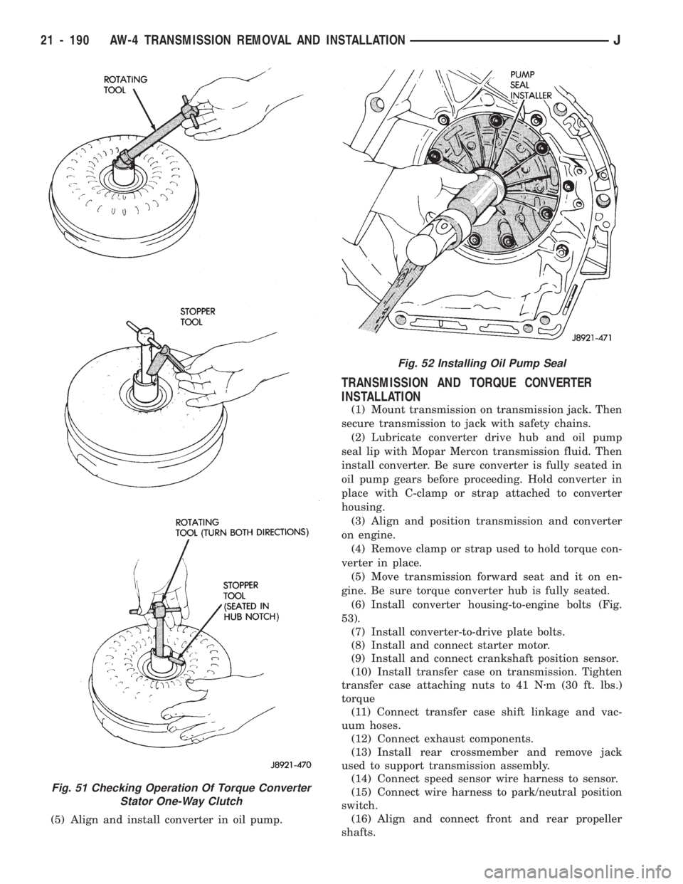
Fig. 51 Checking Operation Of Torque Converter
Stator One-Way Clutch
Fig. 52 Installing Oil Pump Seal
21 - 190 AW-4 TRANSMISSION REMOVAL AND INSTALLATIONJ
Page 1452 of 1784
Radial runout of more than 1.5 mm (.060 inch)
measured at the center line of the tread may cause
the vehicle to shake.
Lateral runout of more than 2.0 mm (.080 inch)
measured near the shoulder of the tire may cause the
vehicle to shake.
Sometimes radial runout can be reduced. Relocate
the wheel and tire assembly on the mounting studs
(See Method 1). If this does not reduce runout to an
acceptable level, the tire can be rotated on the wheel.
(See Method 2).
METHOD 1 (RELOCATE WHEEL ON HUB)
Check accuracy of the wheel mounting surface; ad-
just wheel bearings.
Drive vehicle a short distance to eliminate tire flat
spotting from a parked position.
Make sure all wheel nuts are properly torqued.
Relocate wheel on the mounting, two studs over
from the original position.
Re-tighten wheel nuts until all are properly
torqued, to eliminate brake distortion.
Check radial runout. If still excessive, mark tire
sidewall, wheel, and stud at point of maximum
runout and proceed to Method 2.
METHOD 2 (RELOCATE TIRE ON WHEEL)
Rotating tire on wheel is particularly effective
when there is runout in both tire and wheel.Remove tire from wheel and re-mount wheel on
hub in former position.
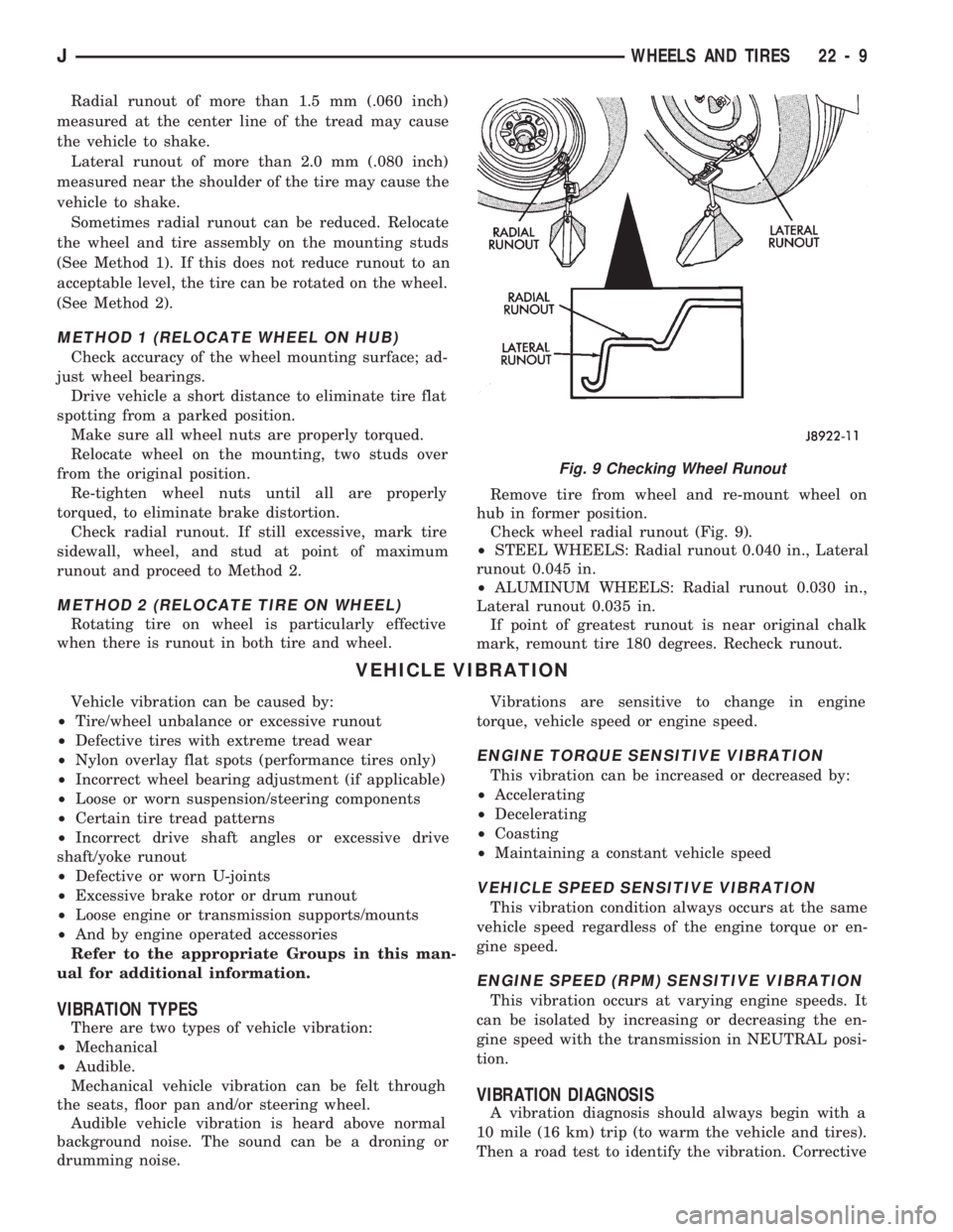
Check wheel radial runout (Fig. 9).
²STEEL WHEELS: Radial runout 0.040 in., Lateral
runout 0.045 in.
²ALUMINUM WHEELS: Radial runout 0.030 in.,
Lateral runout 0.035 in.
If point of greatest runout is near original chalk
mark, remount tire 180 degrees. Recheck runout.
VEHICLE VIBRATION
Vehicle vibration can be caused by:
²Tire/wheel unbalance or excessive runout
²Defective tires with extreme tread wear
²Nylon overlay flat spots (performance tires only)
²Incorrect wheel bearing adjustment (if applicable)
²Loose or worn suspension/steering components
²Certain tire tread patterns
²Incorrect drive shaft angles or excessive drive
shaft/yoke runout
²Defective or worn U-joints
²Excessive brake rotor or drum runout
²Loose engine or transmission supports/mounts
²And by engine operated accessories
Refer to the appropriate Groups in this man-
ual for additional information.
VIBRATION TYPES
There are two types of vehicle vibration:
²Mechanical
²Audible.
Mechanical vehicle vibration can be felt through
the seats, floor pan and/or steering wheel.
Audible vehicle vibration is heard above normal
background noise. The sound can be a droning or
drumming noise.Vibrations are sensitive to change in engine
torque, vehicle speed or engine speed.
ENGINE TORQUE SENSITIVE VIBRATION
This vibration can be increased or decreased by:
²Accelerating
²Decelerating
²Coasting
²Maintaining a constant vehicle speed
VEHICLE SPEED SENSITIVE VIBRATION
This vibration condition always occurs at the same
vehicle speed regardless of the engine torque or en-
gine speed.
ENGINE SPEED (RPM) SENSITIVE VIBRATION
This vibration occurs at varying engine speeds. It
can be isolated by increasing or decreasing the en-
gine speed with the transmission in NEUTRAL posi-
tion.
VIBRATION DIAGNOSIS
A vibration diagnosis should always begin with a
10 mile (16 km) trip (to warm the vehicle and tires).
Then a road test to identify the vibration. Corrective
Fig. 9 Checking Wheel Runout
JWHEELS AND TIRES 22 - 9
Page 1669 of 1784
(18) Disconnect the charging hoses from the ser-
vice valves.
COMPRESSOR OIL LEVEL
The compressor oil level must be checked and ad-
justed if the system has been discharged rapidly, or
when a component has been replaced. If a replace-
ment compressor is being installed, it must be filled
with new compressor oil (Suniso 5GS, or equivalent).
The normal quantity of oil required for the com-
pressor and entire system is 136 ml (4.6 fluid oz.) for
SD 709 compressor. DO NOT overfill the compressor.
Excessive amounts of oil in the system will hinder
compressor operation and reduce A/C performance.
CAUTION: The compressor is a high speed unit.
Satisfactory operation is dependent on sufficient lu-
brication; however, excess oil will hinder A/C per-
formance.
Two oil level checking procedures are necessary.
Use Procedure (A) when the compressor is being re-
placed and the system was discharged properly (no
oil loss). Use Procedure (B) for routine maintenance
or when checking oil level after replacing a system
component.
In cases where rapid loss of refrigerant and oil
occurred, the system must be evacuated and
purged. Then the compressor must be filled with
the necessary amount of oil to fill the entire sys-
tem.
PROCEDURE A
(1) Remove the oil filler plug, discharge cap and
suction port caps from the original and replacement
compressor.
(2) Use a clean container to drain the oil from the
replacement compressor. Drain the oil through the
oil filler plug hole, the discharge and suction. Then
rotate clutch front plate several times to push the oil
on cylinder out to discharge chamber of cylinder
head and drain the oil from discharge port.
(3) Drain the oil from the original compressor into
a measuring cup or graduated beaker in the same
way as Step 2. Note the amount of oil drained.
(4) Fill the replacement compressor with the same
amount of oil drained from the original compressor
plus 30 ml (1 fluid oz.).
FOR EXAMPLE:ÐIf the old compressor contained
103.5 ml (3.5 fluid oz.) of oil, fill the replacement
compressor with a total of 133 ml (4.5 fluid oz.) of oil.
PROCEDURE B
(1) Start the engine and operate the engine at idle.
(2) Operate the air conditioning system for 10 min-
utes to return the maximum amount of oil in the sys-
tem to the compressor.(3) Stop the engine and disconnect the magnetic
clutch feed wire.
(4) Front-seat the discharge and suction service
valves.
(5) Determine the mounting angle.
(a) Position an Angle Gauge across the flat sur-
faces of the front mounting ears.
(b) Center the bubble.
(c) Read the mounting angle to the closest de-
gree.
(d) These vehicles should have 0É mounting an-
gle.
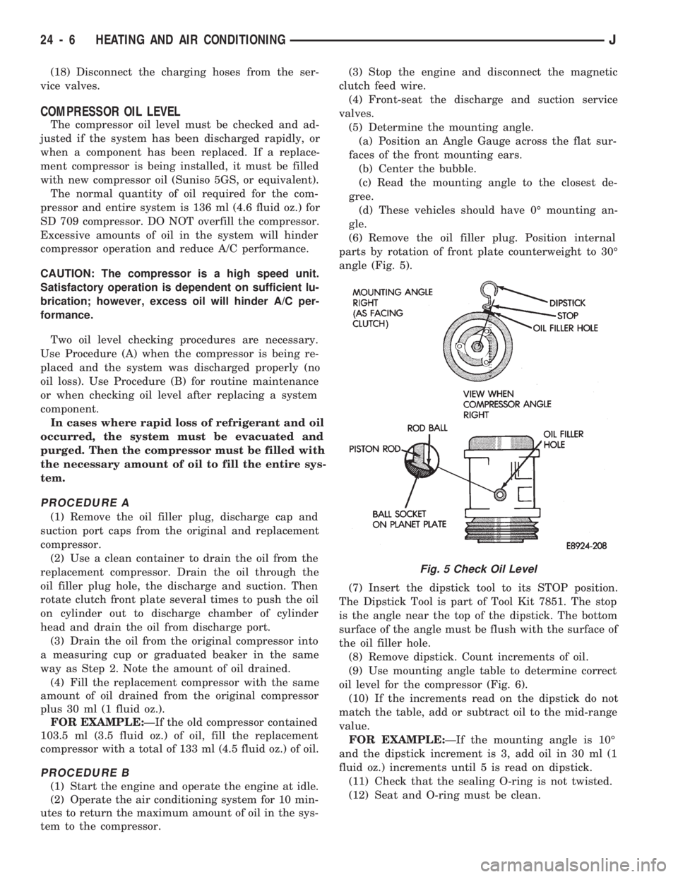
(6) Remove the oil filler plug. Position internal
parts by rotation of front plate counterweight to 30É
angle (Fig. 5).
(7) Insert the dipstick tool to its STOP position.
The Dipstick Tool is part of Tool Kit 7851. The stop
is the angle near the top of the dipstick. The bottom
surface of the angle must be flush with the surface of
the oil filler hole.
(8) Remove dipstick. Count increments of oil.
(9) Use mounting angle table to determine correct
oil level for the compressor (Fig. 6).
(10) If the increments read on the dipstick do not
match the table, add or subtract oil to the mid-range
value.
FOR EXAMPLE:ÐIf the mounting angle is 10É
and the dipstick increment is 3, add oil in 30 ml (1
fluid oz.) increments until 5 is read on dipstick.
(11) Check that the sealing O-ring is not twisted.
(12) Seat and O-ring must be clean.
Fig. 5 Check Oil Level
24 - 6 HEATING AND AIR CONDITIONINGJ
Page 1671 of 1784
SERVICE DIAGNOSISÐMECHANICAL
GENERAL
The reason for a decrease in cooling or heating ef-
ficiency must be understood before attempting repair
or replacement of parts. Determined if the condition
is the air conditioner, the heating system, its compo-
nents or the in the air flow system.
The air conditioning system generally operates at
peak efficiency at normal highway speeds. However,
a slight reduction in A/C performance may be expe-
rienced in congested city driving conditions; espe-
cially when ambient temperatures are high.
When diagnosing a gradual decrease in A/C perfor-
mance, remember to check condition of the condenser
and radiator fins. Air flow blockage of either compo-
nent, caused by dirt, foreign material or insects, will
affect the air conditioning and engine cooling sys-
tems. Vehicles equipped with a protective screen, can
restrict air flow to the radiator and condenser.
During high outside operating temperatures, a
slight increase in engine coolant temperature will oc-
cur when the air conditioner is operating.
A/C PERFORMANCE TEST
The pressure developed on the high side and low
side of the compressor indicates whether the system
is operating properly.
WARNING: USE EXTREME CAUTION WHEN THE
ENGINE IS OPERATING. DO NOT STAND IN A DI-
RECT LINE WITH THE FAN. DO NOT PUT YOUR
HANDS NEAR THE PULLEYS, BELTS OR FAN. DO
NOT WEAR LOOSE CLOTHING.
WARNING: WEAR SAFETY GOGGLES WHEN SER-
VICING THE REFRIGERATION SYSTEM
(1) Attach an engine tachometer and refrigerant
Pressure Gauge and Manifold Assembly Tool
C-4740-A.
(2) Close both hand valves on the gauge and man-
ifold assembly.
(3) Set both service hand valve stems to the mid-
position.
(4) Engine should be warmed up with doors, win-
dows and hood closed.
(5) Operate air conditioning system with the en-
gine running at 1,000 RPM. Set the controls for max-
imum A/C, temperature control on full cool and
blower switch on high.
(6) Insert a thermometer into center discharge air
outlet and observe the air temperature. The temper-
ature should be approximately 7ÉC (45ÉF) at 27ÉC
(80ÉF) ambient temperature after 5 minutes of oper-
ation.(7) Observe the high and low side pressures. The
evaporator suction pressure should be 207-241 kPag
(30-35 psig). The compressor discharge pressure
should be 1103-1633 kPag (160-235 psig). It should
be noted that high ambient temperature and humid-
ity conditions will cause higher pressures and tem-
perature conditions. If the clutch cycles, take
readings before clutch disengages.
(8) If pressures are abnormal, refer to the Pressure
and Performance Diagnosis Charts.
The following charts have been developed for quick
reference. If the step by step method used is not com-
pletely understood, refer to the correct section of the
Service Manual for more detailed information.
COMPRESSOR VALVE PLATEÐLEAK TESTS
This test can be preformed with the compressor in-
stalled in the vehicle.
Discharge or Suction Valve BreakageÐWhen
compressor is operating at idle speed, compressor
makes a ``clacking'' sound. Preform the Pressure Bal-
ancing Test.
Head Gasket BreakageÐAt idle speed, discharge
pressure does not increase to normal condition and
suction pressure is high. Preform the Pressure Bal-
ancing Test.
Pressure Balancing Test:
(1) Connect manifold gauge set to suction and dis-
charge ports.
(2) Run compressor for 5 minutes at idle speed and
stop.
(3) Measure elapsed time that discharge pressure
is balanced to suction pressure. If less than 2 min-
utes, it is determined that discharge valve or head
gasket is broken.
REFRIGERANT LEAK TEST
External leaks in the system can be located using
an electronic detector.
The electronic leak detector is recommended be-
cause it is light, accurate and most important, does
not expose the user to toxic gas fumes. An electronic
leak detector will locate R-12 leaks as small as 15 ml
(0.5 fluid oz.) per year.
WARNING: DO NOT USE A HALIDE TORCH. THE
HALIDE TORCH REQUIRES AN OPEN FLAME FOR
LEAK DETECTION. WHEN R-12 IS EXPOSED TO AN
OPEN FLAME, IT TURNS INTO PHOSGENE GAS
WHICH IS POISONOUS.
(1) Calibrate the detector as outlined in the manu-
facturer's instructions.
(2) Remove the flexible detector probe from the
case.
(3) Turn the detector control switch ON.
24 - 8 HEATING AND AIR CONDITIONINGJ
Page 1677 of 1784
SERVICE DIAGNOSISÐELECTRICAL
BLOWER CONTROLSÐXJ VEHICLES
DESCRIPTION
The blower motor delivers air to the inside of the
vehicle. Its speed is controlled by the blower switch
and the blower resistors. With the switch in LO, part
of the battery voltage is supplied to the motor
through all of the resistors. The motor runs slowly.
As the blower switch is moved to a higher speed, the
switch allows more voltage to be applied to the
blower motor, which will increase its speed. When
the switch is in HI, the blower resistors are bypassed
and battery voltage is applied directly to the blower
motor. The motor runs at the fastest speed in this
mode.
DIAGNOSIS
Refer to the Group 8W, Wiring Diagrams for com-
plete system schematic.
1. BLOWER MOTOR INOPERATIVE
²Remove and inspect fuse. If the fuse is blown, re-
place fuse.
2. BLOWER MOTOR INOPERATIVE (HI Posi-
tion)
Put the ignition switch in RUN, the select switch
in HEAT and the blower switch on HI.
²Blower motor connector (Terminal A) should be
battery voltage. If not go to next step.
²Blower motor connector (Terminal B) should be 0
ohms. If not, repair wire to ground.
²Blower switch connector (Terminal C) should be
battery voltage. If battery voltage replace blower
switch. If not, replace select switch.
3. BLOWER MOTOR INOPERATIVE (LO, M1
& M2 Positions)
Ignition switch in RUN, select switch in HEAT.
²Blower resistors connector (Terminal D) should be
battery voltage. If not, replace select switch.
²Blower resistors connector (Terminal C) should be
battery voltage. If not, replace blower switch.
²Blower resistors connector (Terminal A) should be
battery voltage. If not, replace blower switch.
²Blower resistors connector (Terminal B) should be
battery voltage. If not, replace blower resistor.
AIR CONDITIONING SYSTEMÐXJ VEHICLES
DESCRIPTION
The A/C Compressor Clutch is belt-driven by the
engine. A clutch, operated by a solenoid, automati-
cally turns the compressor on and off to control evap-
orator icing.
The A/C Compressor Clutch operation is controlled
by several components: the A/C Low-Pressure
Switch, Thermostat Switch, Fuel Pump Relay, A/C
Clutch Relay and the Engine Controller.The A/C low pressure switch opens when there is
not enough refrigerant in the system. When this hap-
pens, voltage is no longer present at the Engine Con-
troller. The Engine Controller will turn off the A/C
clutch relay. With the proper refrigerant level in the
system, the low pressure switch remains closed.
When the evaporator temperature is low enough to
ice the cooling coils, the thermostat switch opens.
The Engine Controller will turn off the A/C clutch.
The thermostat switch closes when the temperature
rises. The Engine Controller will then turn the A/C
clutch relay on again.
DIAGNOSIS
Refer to the Group 8W, Wiring Diagrams for com-
plete system schematic.
With engine running, Engine Controller may delay
A/C clutch up to 30 seconds.
1. A/C COMPRESSOR CLUTCH INOPERA-
TIVE
Clutch connector disconnected.
²Jumper fused test lead, battery to clutch connec-
tor, clutch should operate. If not, replace compressor
clutch assembly.
2. A/C LOW PRESSURE SWITCH
Ignition in RUN, A/C controls in MAX or NORM.
²Low pressure switch connector (Terminal A)
should be battery voltage. If not, repair open to select
switch.
²Low pressure switch connector (Terminal C)
should be battery voltage. If not, check switch resis-
tance and check freon pressure.
3. A/C CLUTCH RELAY
Engine RUNNING, A/C controls in MAX or
NORM.
²Relay connector Pin 4 to ground should be battery
voltage. If not, check fuse F6 in Power Distribution
Center.
²Ground A/C clutch relay (Terminal 5) should have
A/C compressor clutch engagement. If not, check En-
gine Controller Terminals 27, 28 and 34.
HEATING SYSTEMÐYJ VEHICLES
DESCRIPTION
The blower motor circuit begins at a 25 amp fuse
that receives its battery feed from the ignition
switch. From the fuse the circuit extends to a micro-
switch mounted on the heater control.
The micro-switch is normally closed is operated by
a cam on the heater control lever. In all heater con-
trol lever positions, except OFF and VENT, the
blower motor electrical circuit is complete. In the
OFF and VENT positions the cam depresses the mi-
cro-switch lever opening the electrical circuit to the
blower motor.
24 - 14 HEATING AND AIR CONDITIONINGJ
Page 1679 of 1784
²Battery side of fuse No.12 should be battery volt-
age. If not, repair open from ignition switch.
²A/C blower switch (terminal A) should be battery
voltage. If not, repair open from fuse No.12.
2. BLOWER SWITCHÐIgnition in RUN.
²A/C blower switch (Terminal A) with blower
switch in any position should be battery voltage. If
not, repair open from fuse panel.
²A/C blower switch (Terminal L) with blower
switch in LO should be battery voltage. If not, re-
place switch.
²A/C blower switch (Terminal M) with blower
switch in MED should be battery voltage. If not, re-
place switch.
²A/C blower switch (Terminal H) with blower
switch in HI should be battery voltage. If not, replace
switch.
3. BLOWER MOTOR
Turn ignition switch to RUN for voltage tests and
turn ignition switch to OFF for resistance tests.
²A/C blower housing to ground (Terminal G) should
be 0 ohms. If not, repair ground connection. If the
blower motor is still inoperative, replace motor.
²A/C blower motor connector (Terminal C) with
blower switch in LO should be battery voltage. If not,
repair open from blower switch. If the blower motor
is still inoperative, replace motor.
²A/C blower motor connector (Terminal B) with
blower switch in MED should be battery voltage. If
not, repair open from blower switch. If the blower
motor is still inoperative, replace motor.
²A/C blower motor connector (Terminal A) with
blower switch in HI should be battery voltage. If not,
repair open from blower switch. If the blower motor
is still inoperative, replace motor.COMPRESSOR CLUTCH
Refer to Group 8W, Wiring Diagrams for complete
system schematic.
With engine running, Engine Controller may delay
A/C clutch up to 30 seconds.
1. COMPRESSOR CLUTCH.
²Jumper wire from battery positive post to A/C
compressor clutch connector (Terminal A), clutch
should engage. If not, go to next step with jumper in-
stalled.
²Jumper wire from clutch coil frame to chassis
ground, clutch should engage. If not, repair clutch
coil ground or replace coil.
2. LOW PRESSURE SWITCH
Turn ignition switch to RUN, A/C blower switch to
ON and thermostatic control set to MAX cool.
²A/C low pressure switch connector (Terminal A)
should be battery voltage. If not, proceed to thermo-
static control tests (Step 3).
²Jumper wire across A/C low pressure switch con-
nector (Terminals A and B), clutch should engage. If
not, check system refrigerant charge. If system is
properly charged, replace A/C low pressure switch.
3. THERMOSTATIC CONTROL
Turn ignition switch to RUN, A/C blower switch to
ON and thermostatic control set to MAX cool.
²Thermostatic control connector (Terminal A)
should be battery voltage. If not, repair open from
blower switch.
²Thermostatic control connector (Terminal B)
should be battery voltage. If not, replace thermo-
static control.
²A/C low pressure switch connector (Terminal A)
should be battery voltage. If not, repair open from
thermostatic control.
24 - 16 HEATING AND AIR CONDITIONINGJ
Page 1680 of 1784
COMPRESSOR OVERHAUL
INDEX
page page
Compressor............................. 17
Compressor Isolation...................... 17
Description............................. 17Magnetic Clutch......................... 18
Purging Compressor of Air................. 17
DESCRIPTION
The A/C system uses a Sanden compressor. This
compressor is a 7 piston design. Designated the SD-
709, the compressor is mounted on the front right
side of the engine and is driven by a serpentine belt.
System lubrication is provided by 135cc615cc (4.6
cu. in.60.5 cu. in.) of 500 viscosity refrigerant oil.
The clutch used on the compressor consists of 3 ba-
sic components: the pulley, front plate and the field
coil. The pulley and field coil are attached to the
front head of the compressor with tapered snap rings.
The hub is keyed to the compressor shaft and is re-
tained on the shaft with a self-locking nut. Special
service tools are required to remove and install the
clutch plate on the compressor shaft.
COMPRESSOR ISOLATION
It is not necessary to discharge the system for com-
pressor removal. The compressor can be isolated from
the remainder of the system and eliminate the need
for recharging when performing compressor service.
(1) Connect pressure gauge and manifold.
(2) Close both gauge hand valves.
(3) Mid-position both service valves.
WARNING: USE EXTREME CAUTION WHEN THE
ENGINE IS OPERATING. DO NOT STAND IN A DI-
RECT LINE WITH THE FAN. DO NOT PUT YOUR
HANDS NEAR THE PULLEYS, BELTS OR FAN. DO
NOT WEAR LOOSE CLOTHING.
(4) Start the engine and operate the air condition-
ing system.
(5) Turn the suction service valve slowly clockwise
toward the front seated position.
(6) When pressure drops to zero, stop the engine
and compressor and quickly finish front-seating the
suction service valve.
(7) Front-seat the discharge service valve.
(8) Loosen the oil level check plug slowly to re-
lease any internal pressure in the compressor.
The compressor is now isolated from the remainder
of the system.
The service valves can be removed from the com-
pressor.
PURGING COMPRESSOR OF AIR
The compressor must be purged of air whenever it
has been isolated for an oil level check or other ser-
vice procedures without discharging the entire sys-
tem.
(1) Cap the service gauge ports on both of the ser-
vice valves.
(2) Back-seat the suction service valve to allow the
system refrigerant to enter the compressor.
(3) Place the discharge service valve in the mid-po-
sition or cracked-position.
(4) Loosen the discharge service valve gauge port
cap to permit the refrigerant to force any air out of
the compressor.
(5) Back-seat the discharge service valve and
tighten the gauge port cap.
(6) The compressor is now ready for service.
COMPRESSOR
REMOVAL
(1) Isolate the compressor.
(2) Disconnect negative cable from battery.
(3) Disconnect the clutch lead wire.
(4) Remove the discharge and inlet (suction) ser-
vice valves from the compressor. Plug or tape all the
openings.
(5) Remove the serpentine drive belt (refer to
Group 7, Cooling System for the proper procedure).
(6) Remove the bolts and lift the compressor from
the mounting bracket (Figs. 1 and 2).
INSTALLATION
If a replacement compressor is being installed;
check the oil level. Add or subtract oil as neces-
sary and install the magnetic clutch on the com-
pressor.
(1) If the mounting bracket was removed, install
the bracket to the block. Tighten the mounting bolts
to 27 NIm (20 ft. lbs.) torque.
(2) Install the compressor on the mounting
bracket. Tighten the bolts to 27 NIm (20 ft. lbs.)
torque.
(3) Install the serpentine drive belt (refer to Group
7, Cooling System for the proper procedure).
(4) Tighten the serpentine drive belt to the speci-
fied tension.
²New belt tensionÐ800-900 N (180-200 lb-f).
JHEATING AND AIR CONDITIONING 24 - 17
Page 1685 of 1784
CLIMATE CONTROL SYSTEMÐXJ VEHICLES
INDEX
page page
A/C Recirculating Air Door Vacuum Motor
Replacement.......................... 31
Blower Motor Resistors Replacement......... 35
Blower Motor/Fan Replacement.............. 26
CondenserÐ4.0L Engines.................. 32
Condenser/Receiver DrierÐ2.5L Engines....... 31
Defroster Duct Replacement................ 29
Description............................. 22
Evaporator Coil.......................... 34
Evaporator/Blower Housing................. 33Expansion (H) Valve...................... 35
Heater and A/C Control Panel Replacement.... 26
Heater Control Cable Replacement........... 30
Heater Core............................ 28
Heater Core Housing Replacement........... 29
Heater/Defroster/Instrument Panel Outlet Door
Vacuum Motor Replacement............... 30
Receiver DrierÐ4.0L Engines............... 32
Temperature Control Thermostat............. 35
DESCRIPTION
The Climate Control System combines air condi-
tioning, heating and ventilating capabilities for vehi-
cles equipped with air conditioning. Vehicles without
air conditioning perform heating and ventilating
functions without the air conditioning evaporator.
Both systems consist basically of 2 parts:
²Blower and Air Inlet Assembly
²Heater Core and Air Distribution Assembly
These assemblies, initially installed as a single
unit, may be removed separately from under the in-
strument panel as required for service.
HEATER SYSTEM
The heater system is a blend air type. Outside air
is heated and then blended in varying amounts with
cooler outside air to obtain the desired discharge
temperature. A heater coolant valve provides full
flow to the heater core for all heating modes. The
heater coolant valve remains closed for the ventila-
tion mode, allowing discharge air to approach the
outside ambient air temperature.
AIR CONDITIONING SYSTEM
The air conditioning system has an evaporator to
cool and dehumidify the incoming outside air prior to
blending with the heated air. The evaporator is in
operation during the A/C mode and also in the de-
frost mode for defogging purposes. The evaporator is
not in operation at ambient temperatures below ap-
proximately -1ÉC (30ÉF). To maintain minimum evap-
orator temperature, a fixed thermostat setting switch
cycles the compressor clutch. The blower is operatingthe heater or air conditioning systems, except the
OFF mode. In this mode (OFF) the blower and the
outside air are shut off.
The cooling unit is mounted on the dash panel and
the cooled air is discharged from the instrument
panel registers. The registers are adjusted to provide
general or localized cooling.
SIGHT GLASS
The sight glass is located on top of the receiver/
drier. The sight glass provides a visual check of the
system refrigerant level. A continuous stream of bub-
bles will appear in the sight glass when the system
charge is low. Bubbles will not appear when the sys-
tem is fully charged.
LOW PRESSURE SWITCH
The low pressure switch disengages the magnetic
clutch if the pressure in the system drops below 193
kPa (28 psi). This will occur with a loss in refriger-
ant or with cold ambient temperature.
HEATER VALVE
The heater valve regulates coolant flow to the
heater core. It requires vacuum to shut off flow to
the heater core.
These vehicles are equipped with a bypass-type
heater water valve. When the heater valve is closed,
coolant flow to the heater core is bypassed back to
the engine. When the heater valve is open, coolant is
directed through the heater core and back to the en-
gine.
24 - 22 HEATING AND AIR CONDITIONINGJ
Page 1703 of 1784
HEATER CORE AND HOUSING
REMOVAL
WARNING: HOT ENGINE COOLANT CAN CAUSE
SEVERE BURNS. DO NOT OPEN THE RADIATOR
DRAIN COCK WHEN THE COOLING SYSTEM IS
HOT AND PRESSURIZED. ALLOW THE COOLANT
TO DECREASE TO ROOM TEMPERATURE BEFORE
STARTING REPAIR OPERATIONS.
(1) Drain approximately 1.9 liters (2 qts) of coolant
from the radiator. Drain the coolant into a clean con-
tainer.
(2) Disconnect the heater hoses.
(3) Disconnect the vent door cables.
(4) Disconnect the blower motor wire.
(5) Disconnect the defroster duct.
(6) Remove the nuts that attach the heater hous-
ing studs to the engine compartment side of the dash
panel.
(7) Remove the heater housing assembly by tilting
it downward, to disengage it from the defroster duct.
Pull it rearward and out from under the instrument
panel.
(8) Remove the heater hosing cover from the hous-
ing.
(9) Remove the heater core from the housing.
INSTALLATION
(1) Install the heater core in the housing and in-
stall the cover on the housing.
(2) Position the heater housing on the dash panel.
Be sure the housing studs all extend through the
dash panel.
(3) Install the seals on the heater core outlet and
inlet tubes and over the blower motor housing.
(4) Install the attaching nuts on the housing studs.
CAUTION: DO NOT over tighten the attaching nuts.
The housing could become distorted causing air
leaks and improper heater door operation. Tighten
the nuts alternately and evenly until 2 stud threads
are visible beyond each nut.
(5) Connect the defroster duct to the housing.
(6) Connect the blower motor wire.
(7) Connect the vent door control cables.
(8) Connect the heater hoses.
(9) Fill and bleed the cooling system.
(10) Check system operation.
BLOWER MOTOR (HEATING)
REMOVAL
(1) Remove the heater housing.
(2) Remove the blower motor-to-heater housing at-
taching screws/nuts.
(3) Remove the blower motor from the housing.
INSTALLATION
(1) Position the blower motor into the housing.
(2) Install and tighten the blower motor-to-heater
housing attaching screws/nuts.
(3) Install the heater housing.
(4) Check blower motor and heater operation.
DEFROSTER NOZZLE AND DUCT
REMOVAL
WARNING: HOT ENGINE COOLANT CAN CAUSE
SEVERE BURNS. DO NOT OPEN THE RADIATOR
DRAIN COCK WHEN THE COOLING SYSTEM IS
HOT AND PRESSURIZED. ALLOW THE COOLANT
TO DECREASE TO ROOM TEMPERATURE BEFORE
STARTING REPAIR OPERATIONS.
(1) Drain approximately 1.9 liters (2 qts) of coolant
from the radiator. Drain the coolant into a clean con-
tainer.
(2) Disconnect the heater hoses.
(3) Remove the nuts attaching the heater housing
studs to the engine compartment side of the dash
panel.
(4) Disconnect the speedometer cable.
(5) Remove the glove box.
(6) Tilt the heater housing back and pull it rear-
ward and out from under the instrument panel.
(7) Disconnect the vent control cables.
(8) Remove the fresh air intake grille from the
cowl.
(9) Remove the fresh air intake duct.
(10) Lower the windshield.
(11) Remove the defroster nozzle attaching screws
and remove the nozzle and duct.
INSTALLATION
(1) Install the defroster nozzle and duct.
(2) Raise and secure the windshield.
(3) Install the fresh air intake duct.
(4) Install the fresh air intake grille on the cowl.
(5) Install the vent cables.
(6) Position the heater housing on the dash panel.
Be sure all the housing studs extend through the
dash panel.
(7) Install the seals on the blower motor and the
heater core inlet and outlet tubes.
(8) Install the attaching nuts on the housing studs.
CAUTION: DO NOT over tighten the attaching nuts.
The housing could become distorted causing air
leaks and improper heater door operation. Tighten
the nuts alternately and evenly until 2 stud threads
are visible beyond each nut.
(9) Install the glove box.
(10) Connect the speedometer cable.
(11) Connect the heater hoses.
24 - 40 HEATING AND AIR CONDITIONINGJ
Page 1704 of 1784
(12) Fill and bleed the cooling system.
FRESH AIR DOOR VACUUM MOTOR
REMOVAL
(1) Remove the glove box and assist handle.
(2) Disconnect the vacuum hose from the motor.
(3) Remove the motor lever retaining clip.
(4) Remove the motor attaching nuts and remove
the motor from the fresh air duct.
INSTALLATION
(1) Position the motor on the fresh air duct and in-
stall the motor attaching nuts.
(2) Align the motor lever with the air door lever
and install the lever retaining clip.
(3) Connect the vacuum hose to the motor.
(4) Install the glove box and assist handle.
FRESH AIR INTAKE DUCT
REMOVAL
WARNING: HOT ENGINE COOLANT CAN CAUSE
SEVERE BURNS. DO NOT OPEN THE RADIATOR
DRAIN COCK WHEN THE COOLING SYSTEM IS
HOT AND PRESSURIZED. ALLOW THE COOLANT
TO DECREASE TO ROOM TEMPERATURE BEFORE
STARTING REPAIR OPERATIONS.
(1) Drain approximately 1.9 liters (2 qts) of coolant
from the radiator. Drain the coolant into a clean con-
tainer.
(2) Disconnect the heater hoses.
(3) Remove the nuts attaching the heater housing
studs to the dash panel from inside the engine com-
partment.
(4) Disconnect the speedometer cable.
(5) Remove the glove box and assist handle.
(6) Tilt the heater housing back and pull it rear-
ward and out from under the instrument panel.
(7) Disconnect the vent cables.
(8) Remove the fresh air intake grille from the
cowl.
(9) Remove the fresh air intake duct.
INSTALLATION
(1) Install the fresh air intake duct.
(2) Install the defroster nozzle and duct.
(3) Raise and secure the windshield.
(4) Install the fresh air grille on the cowl.
(5) Install the vent cables.
(6) Position the heater housing on the dash panel.
Be sure all the housing studs extend through the
dash panel.
(7) Install the seals on the blower motor and
heater core inlet and outlet tubes.
(8) Install the attaching nuts on the heater hous-
ing studs.CAUTION: DO NOT over tighten the attaching nuts.
The housing could become distorted causing air
leaks and improper heater door operation. Tighten
the nuts alternately and evenly until 2 stud threads
are visible beyond each nut.
(9) Install the glove box and assist handle.
(10) Connect the speedometer cable.
(11) Connect the heater hoses.
(12) Fill and bleed the cooling system.
DESCRIPTION (AIR CONDITIONING)
The evaporator, blower fan and motor, thermostat,
expansion valve, capillary tube, air outlets and sys-
tem controls are located in the evaporator housing.
The evaporator housing is mounted under the instru-
ment panel. The compressor, condenser, receiver-
dryer and refrigerant lines are located in the engine
compartment.
A rotary-type compressor with magnetic clutch op-
erated drive pulley is used for all vehicles equipped
with air conditioning.
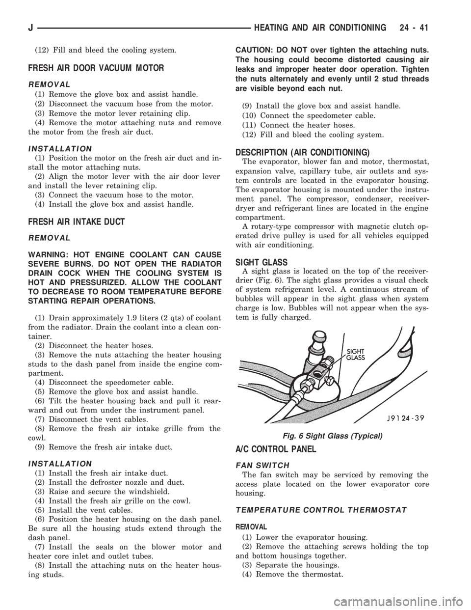
SIGHT GLASS
A sight glass is located on the top of the receiver-
drier (Fig. 6). The sight glass provides a visual check
of system refrigerant level. A continuous stream of
bubbles will appear in the sight glass when system
charge is low. Bubbles will not appear when the sys-
tem is fully charged.
A/C CONTROL PANEL
FAN SWITCH
The fan switch may be serviced by removing the
access plate located on the lower evaporator core
housing.
TEMPERATURE CONTROL THERMOSTAT
REMOVAL
(1) Lower the evaporator housing.
(2) Remove the attaching screws holding the top
and bottom housings together.
(3) Separate the housings.
(4) Remove the thermostat.
Fig. 6 Sight Glass (Typical)
JHEATING AND AIR CONDITIONING 24 - 41