sensor JEEP CHEROKEE 1994 Service Repair Manual
[x] Cancel search | Manufacturer: JEEP, Model Year: 1994, Model line: CHEROKEE, Model: JEEP CHEROKEE 1994Pages: 1784, PDF Size: 77.09 MB
Page 1300 of 1784
AW-4 TRANSMISSION REMOVAL AND INSTALLATION
INDEX
page page
Oil Pump Seal Replacement............... 189
Torque Converter Stator Clutch Inspection..... 189Transmission and Torque Converter Installation . 190
Transmission and Torque Converter Removal . . 189
TRANSMISSION AND TORQUE CONVERTER
REMOVAL
(1) Raise vehicle.
(2) Drain transmission fluid and reinstall oil pan
drain plug.
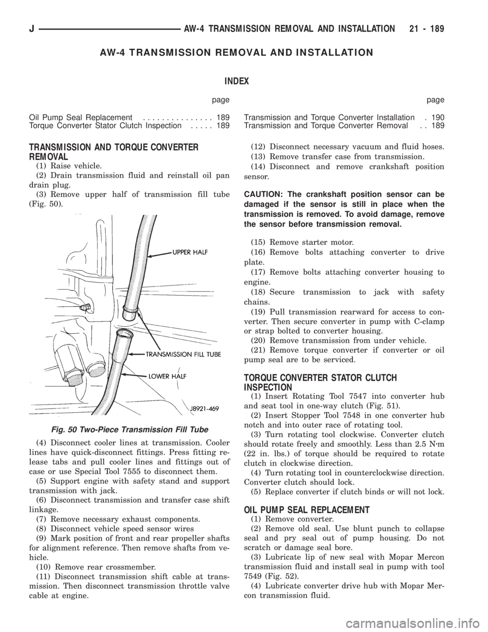
(3) Remove upper half of transmission fill tube
(Fig. 50).
(4) Disconnect cooler lines at transmission. Cooler
lines have quick-disconnect fittings. Press fitting re-
lease tabs and pull cooler lines and fittings out of
case or use Special Tool 7555 to disconnect them.
(5) Support engine with safety stand and support
transmission with jack.
(6) Disconnect transmission and transfer case shift
linkage.
(7) Remove necessary exhaust components.
(8) Disconnect vehicle speed sensor wires
(9) Mark position of front and rear propeller shafts
for alignment reference. Then remove shafts from ve-
hicle.
(10) Remove rear crossmember.
(11) Disconnect transmission shift cable at trans-
mission. Then disconnect transmission throttle valve
cable at engine.(12) Disconnect necessary vacuum and fluid hoses.
(13) Remove transfer case from transmission.
(14) Disconnect and remove crankshaft position
sensor.
CAUTION: The crankshaft position sensor can be
damaged if the sensor is still in place when the
transmission is removed. To avoid damage, remove
the sensor before transmission removal.
(15) Remove starter motor.
(16) Remove bolts attaching converter to drive
plate.
(17) Remove bolts attaching converter housing to
engine.
(18) Secure transmission to jack with safety
chains.
(19) Pull transmission rearward for access to con-
verter. Then secure converter in pump with C-clamp
or strap bolted to converter housing.
(20) Remove transmission from under vehicle.
(21) Remove torque converter if converter or oil
pump seal are to be serviced.
TORQUE CONVERTER STATOR CLUTCH
INSPECTION
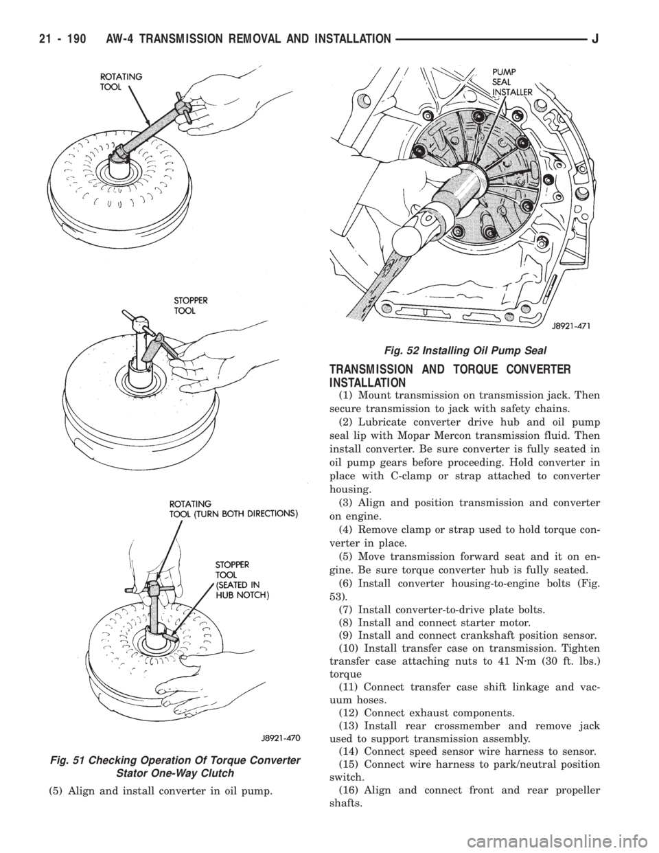
(1) Insert Rotating Tool 7547 into converter hub
and seat tool in one-way clutch (Fig. 51).
(2) Insert Stopper Tool 7548 in one converter hub
notch and into outer race of rotating tool.
(3) Turn rotating tool clockwise. Converter clutch
should rotate freely and smoothly. Less than 2.5 Nzm
(22 in. lbs.) of torque should be required to rotate
clutch in clockwise direction.
(4) Turn rotating tool in counterclockwise direction.
Converter clutch should lock.
(5)
Replace converter if clutch binds or will not lock.
OIL PUMP SEAL REPLACEMENT
(1) Remove converter.
(2) Remove old seal. Use blunt punch to collapse
seal and pry seal out of pump housing. Do not
scratch or damage seal bore.
(3) Lubricate lip of new seal with Mopar Mercon
transmission fluid and install seal in pump with tool
7549 (Fig. 52).
(4) Lubricate converter drive hub with Mopar Mer-
con transmission fluid.
Fig. 50 Two-Piece Transmission Fill Tube
JAW-4 TRANSMISSION REMOVAL AND INSTALLATION 21 - 189
Page 1301 of 1784
(5) Align and install converter in oil pump.
TRANSMISSION AND TORQUE CONVERTER
INSTALLATION
(1) Mount transmission on transmission jack. Then
secure transmission to jack with safety chains.
(2) Lubricate converter drive hub and oil pump
seal lip with Mopar Mercon transmission fluid. Then
install converter. Be sure converter is fully seated in
oil pump gears before proceeding. Hold converter in
place with C-clamp or strap attached to converter
housing.
(3) Align and position transmission and converter
on engine.
(4) Remove clamp or strap used to hold torque con-
verter in place.
(5) Move transmission forward seat and it on en-
gine. Be sure torque converter hub is fully seated.
(6)
Install converter housing-to-engine bolts (Fig.
53).
(7) Install converter-to-drive plate bolts.
(8) Install and connect starter motor.
(9) Install and connect crankshaft position sensor.
(10) Install transfer case on transmission. Tighten
transfer case attaching nuts to 41 Nzm (30 ft. lbs.)
torque
(11) Connect transfer case shift linkage and vac-
uum hoses.
(12) Connect exhaust components.
(13) Install rear crossmember and remove jack
used to support transmission assembly.
(14) Connect speed sensor wire harness to sensor.
(15) Connect wire harness to park/neutral position
switch.
(16) Align and connect front and rear propeller
shafts.
Fig. 51 Checking Operation Of Torque Converter
Stator One-Way Clutch
Fig. 52 Installing Oil Pump Seal
21 - 190 AW-4 TRANSMISSION REMOVAL AND INSTALLATIONJ
Page 1303 of 1784
AW-4 TRANSMISSION OVERHAUL
INDEX
page page
Cleaning and Inspection................... 76
Direct Clutch Overhaul................... 219
First-Reverse Brake Piston and Transmission
Case Overhaul........................ 237
Forward Clutch Overhaul.................. 223
Front Planetary Gear Overhaul............. 228
Manual Valve Shaft Overhaul.............. 205
Oil Pump Overhaul...................... 206
Overdrive Planetary Gear and Clutch Overhaul . 209Overdrive Support Overhaul................ 216
Overhaul Service Tools................... 192
Rear Planetary, No. 2 One-Way Clutch and
Output Shaft Overhaul.................. 100
Second Brake Overhaul................... 100
Sun Gear and No. 1 One-Way Clutch Overhaul . 99
Transmission Assembly and Adjustment....... 255
Transmission Disassembly................. 192
Transmission Valve Body Overhaul.......... 101
OVERHAUL SERVICE TOOLS
The special tools needed to overhaul the AW-4
transmission are provided in Tool Kit 6294. However,
Pressure Test Port Adapter 7554 is not included in
this kit and must be ordered separately. The over-
haul tool kit and test port adapter are available
through the parts division and dealer special tool
program.
TRANSMISSION DISASSEMBLY
(1) Remove torque converter.
(2) Remove lower half of filler tube if not previ-
ously removed.
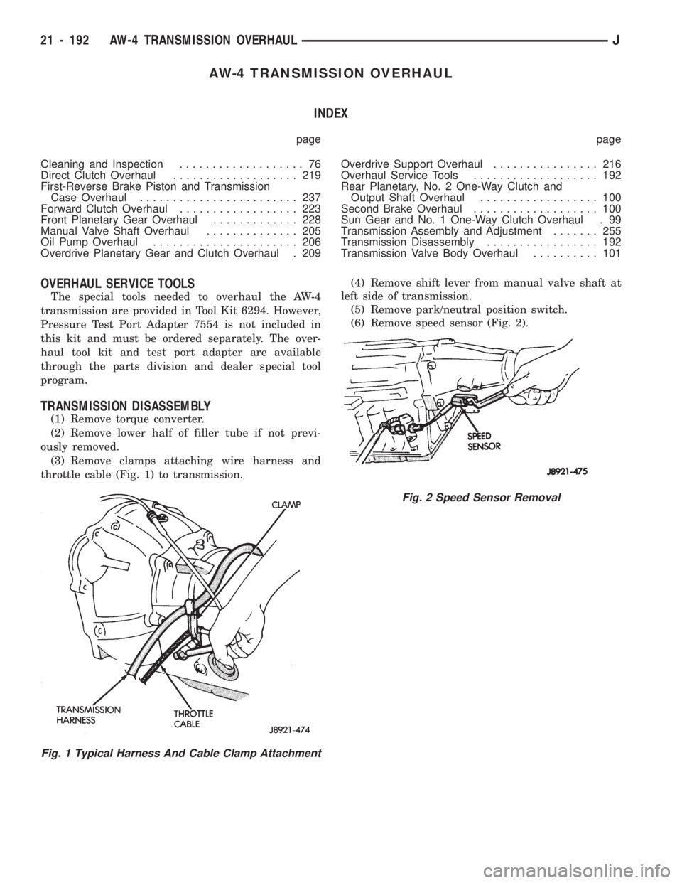
(3) Remove clamps attaching wire harness and
throttle cable (Fig. 1) to transmission.(4) Remove shift lever from manual valve shaft at
left side of transmission.
(5) Remove park/neutral position switch.
(6) Remove speed sensor (Fig. 2).
Fig. 1 Typical Harness And Cable Clamp Attachment
Fig. 2 Speed Sensor Removal
21 - 192 AW-4 TRANSMISSION OVERHAULJ
Page 1304 of 1784
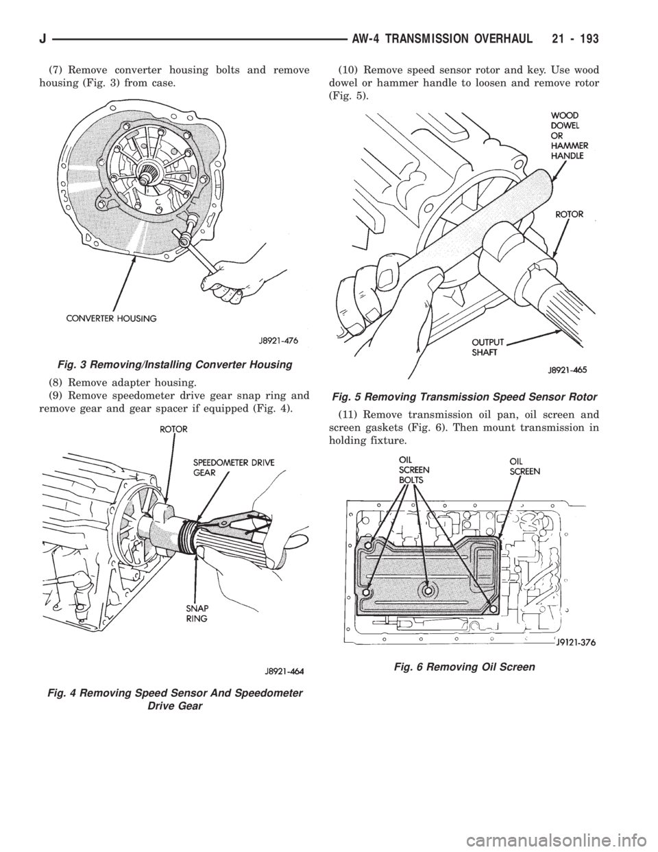
(7) Remove converter housing bolts and remove
housing (Fig. 3) from case.
(8) Remove adapter housing.
(9) Remove speedometer drive gear snap ring and
remove gear and gear spacer if equipped (Fig. 4).(10) Remove speed sensor rotor and key. Use wood
dowel or hammer handle to loosen and remove rotor
(Fig. 5).
(11) Remove transmission oil pan, oil screen and
screen gaskets (Fig. 6). Then mount transmission in
holding fixture.
Fig. 3 Removing/Installing Converter Housing
Fig. 4 Removing Speed Sensor And Speedometer
Drive Gear
Fig. 5 Removing Transmission Speed Sensor Rotor
Fig. 6 Removing Oil Screen
JAW-4 TRANSMISSION OVERHAUL 21 - 193
Page 1380 of 1784
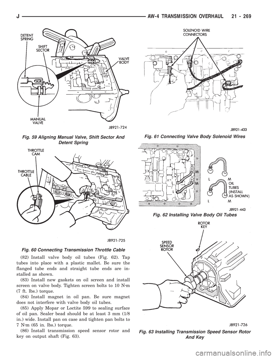
(82) Install valve body oil tubes (Fig. 62). Tap
tubes into place with a plastic mallet. Be sure the
flanged tube ends and straight tube ends are in-
stalled as shown.
(83) Install new gaskets on oil screen and install
screen on valve body. Tighten screen bolts to 10 Nzm
(7 ft. lbs.) torque.
(84) Install magnet in oil pan. Be sure magnet
does not interfere with valve body oil tubes.
(85) Apply Mopar or Loctite 599 to sealing surface
of oil pan. Sealer bead should be at least 3 mm (1/8
in.) wide. Install pan on case and tighten pan bolts to
7Nzm (65 in. lbs.) torque.
(86) Install transmission speed sensor rotor and
key on output shaft (Fig. 63).
Fig. 63 Installing Transmission Speed Sensor Rotor
And Key
Fig. 61 Connecting Valve Body Solenoid Wires
Fig. 62 Installing Valve Body Oil Tubes
Fig. 59 Aligning Manual Valve, Shift Sector And
Detent Spring
Fig. 60 Connecting Transmission Throttle Cable
JAW-4 TRANSMISSION OVERHAUL 21 - 269
Page 1381 of 1784
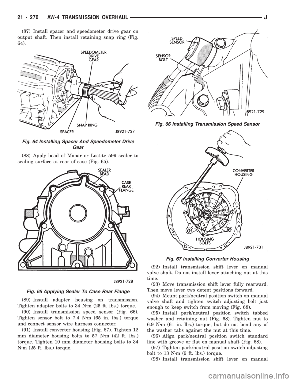
(87) Install spacer and speedometer drive gear on
output shaft. Then install retaining snap ring (Fig.
64).
(88) Apply bead of Mopar or Loctite 599 sealer to
sealing surface at rear of case (Fig. 65).
(89) Install adapter housing on transmission.
Tighten adapter bolts to 34 Nzm (25 ft. lbs.) torque.
(90) Install transmission speed sensor (Fig. 66).
Tighten sensor bolt to 7.4 Nzm (65 in. lbs.) torque
and connect sensor wire harness connector.
(91) Install converter housing (Fig. 67). Tighten 12
mm diameter housing bolts to 57 Nzm (42 ft. lbs.)
torque. Tighten 10 mm diameter housing bolts to 34
Nzm (25 ft. lbs.) torque.(92) Install transmission shift lever on manual
valve shaft. Do not install lever attaching nut at this
time.
(93) Move transmission shift lever fully rearward.
Then move lever two detent positions forward.
(94) Mount park/neutral position switch on manual
valve shaft and tighten switch adjusting bolt just
enough to keep switch from moving (Fig. 68).
(95) Install park/neutral position switch tabbed
washer and retaining nut (Fig. 68). Tighten nut to
6.9 Nzm (61 in. lbs.) torque, but do not bend any of
the washer tabs against the nut at this time.
(96) Align park/neutral position switch standard
line with groove or flat on manual shaft (Fig. 68).
(97) Tighten park/neutral position switch adjusting
bolt to 13 Nzm (9 ft. lbs.) torque.
(98) Install transmission shift lever on manual
Fig. 66 Installing Transmission Speed Sensor
Fig. 67 Installing Converter Housing
Fig. 64 Installing Spacer And Speedometer Drive
Gear
Fig. 65 Applying Sealer To Case Rear Flange
21 - 270 AW-4 TRANSMISSION OVERHAULJ
Page 1387 of 1784
TRANSFER CASE REMOVAL
(1) Shift transfer case into Neutral.
(2) Raise vehicle.
(3) Drain transfer case lubricant.
(4) Mark front and rear propeller shaft yokes for
alignment reference.
(5) Support transmission with jack stand.
(6) Remove rear crossmember, or skid plate.
(7) Disconnect front/rear propeller shafts at trans-
fer case.
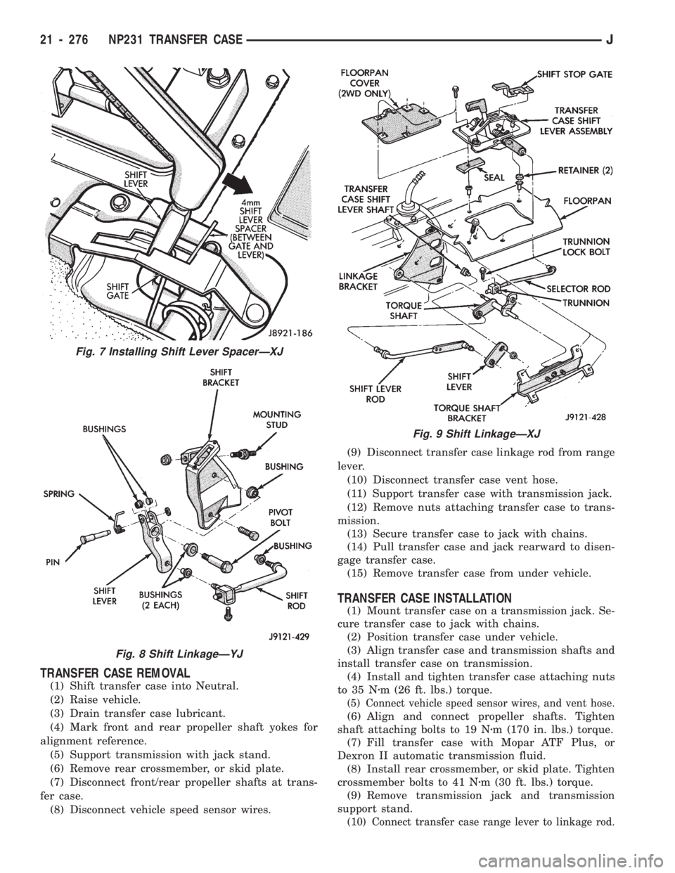
(8) Disconnect vehicle speed sensor wires.(9) Disconnect transfer case linkage rod from range
lever.
(10) Disconnect transfer case vent hose.
(11) Support transfer case with transmission jack.
(12) Remove nuts attaching transfer case to trans-
mission.
(13) Secure transfer case to jack with chains.
(14) Pull transfer case and jack rearward to disen-
gage transfer case.
(15) Remove transfer case from under vehicle.
TRANSFER CASE INSTALLATION
(1) Mount transfer case on a transmission jack. Se-
cure transfer case to jack with chains.
(2) Position transfer case under vehicle.
(3) Align transfer case and transmission shafts and
install transfer case on transmission.
(4) Install and tighten transfer case attaching nuts
to 35 Nzm (26 ft. lbs.) torque.
(5) Connect vehicle speed sensor wires, and vent hose.
(6) Align and connect propeller shafts. Tighten
shaft attaching bolts to 19 Nzm (170 in. lbs.) torque.
(7) Fill transfer case with Mopar ATF Plus, or
Dexron II automatic transmission fluid.
(8) Install rear crossmember, or skid plate. Tighten
crossmember bolts to 41 Nzm (30 ft. lbs.) torque.
(9) Remove transmission jack and transmission
support stand.
(10) Connect transfer case range lever to linkage rod.
Fig. 7 Installing Shift Lever SpacerÐXJ
Fig. 8 Shift LinkageÐYJ
Fig. 9 Shift LinkageÐXJ
21 - 276 NP231 TRANSFER CASEJ
Page 1407 of 1784
SHIFT LINKAGE ADJUSTMENT
(1) Remove shift lever bezel.
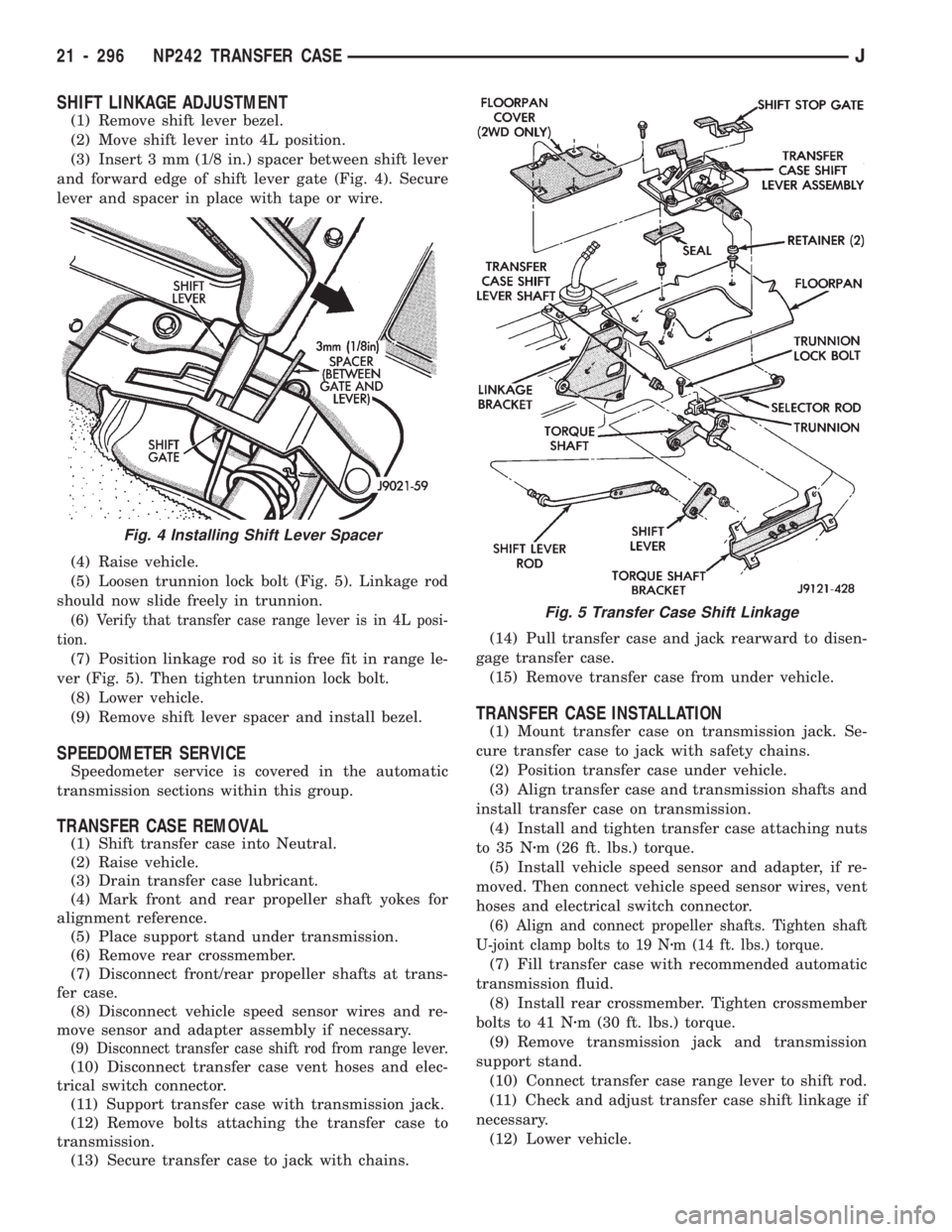
(2) Move shift lever into 4L position.
(3) Insert 3 mm (1/8 in.) spacer between shift lever
and forward edge of shift lever gate (Fig. 4). Secure
lever and spacer in place with tape or wire.
(4) Raise vehicle.
(5) Loosen trunnion lock bolt (Fig. 5). Linkage rod
should now slide freely in trunnion.
(6) Verify that transfer case range lever is in 4L posi-
tion.
(7) Position linkage rod so it is free fit in range le-
ver (Fig. 5). Then tighten trunnion lock bolt.
(8) Lower vehicle.
(9) Remove shift lever spacer and install bezel.
SPEEDOMETER SERVICE
Speedometer service is covered in the automatic
transmission sections within this group.
TRANSFER CASE REMOVAL
(1) Shift transfer case into Neutral.
(2) Raise vehicle.
(3) Drain transfer case lubricant.
(4) Mark front and rear propeller shaft yokes for
alignment reference.
(5) Place support stand under transmission.
(6) Remove rear crossmember.
(7) Disconnect front/rear propeller shafts at trans-
fer case.
(8) Disconnect vehicle speed sensor wires and re-
move sensor and adapter assembly if necessary.
(9) Disconnect transfer case shift rod from range lever.
(10) Disconnect transfer case vent hoses and elec-
trical switch connector.
(11) Support transfer case with transmission jack.
(12) Remove bolts attaching the transfer case to
transmission.
(13) Secure transfer case to jack with chains.(14) Pull transfer case and jack rearward to disen-
gage transfer case.
(15) Remove transfer case from under vehicle.
TRANSFER CASE INSTALLATION
(1) Mount transfer case on transmission jack. Se-
cure transfer case to jack with safety chains.
(2) Position transfer case under vehicle.
(3) Align transfer case and transmission shafts and
install transfer case on transmission.
(4) Install and tighten transfer case attaching nuts
to 35 Nzm (26 ft. lbs.) torque.
(5) Install vehicle speed sensor and adapter, if re-
moved. Then connect vehicle speed sensor wires, vent
hoses and electrical switch connector.
(6) Align and connect propeller shafts. Tighten shaft
U-joint clamp bolts to 19 Nzm (14 ft. lbs.) torque.
(7) Fill transfer case with recommended automatic
transmission fluid.
(8) Install rear crossmember. Tighten crossmember
bolts to 41 Nzm (30 ft. lbs.) torque.
(9) Remove transmission jack and transmission
support stand.
(10) Connect transfer case range lever to shift rod.
(11) Check and adjust transfer case shift linkage if
necessary.
(12) Lower vehicle.
Fig. 4 Installing Shift Lever Spacer
Fig. 5 Transfer Case Shift Linkage
21 - 296 NP242 TRANSFER CASEJ
Page 1725 of 1784
EXHAUST EMISSION CONTROLS
INDEX
page page
Air Cleaner.............................. 7Oxygen (O2S) Sensor...................... 7
AIR CLEANER
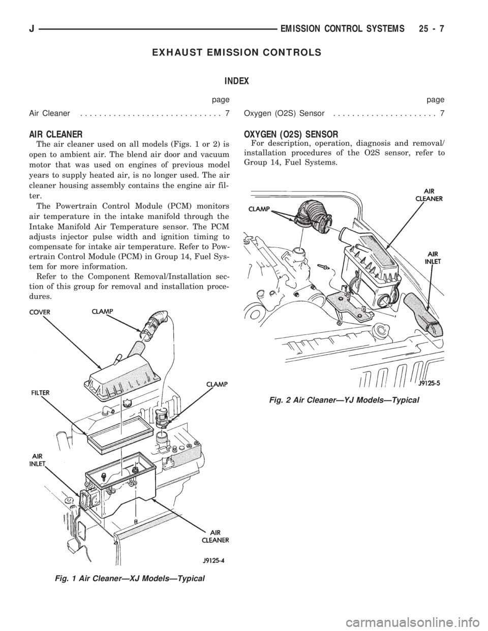
The air cleaner used on all models (Figs. 1 or 2) is
open to ambient air. The blend air door and vacuum
motor that was used on engines of previous model
years to supply heated air, is no longer used. The air
cleaner housing assembly contains the engine air fil-
ter.
The Powertrain Control Module (PCM) monitors
air temperature in the intake manifold through the
Intake Manifold Air Temperature sensor. The PCM
adjusts injector pulse width and ignition timing to
compensate for intake air temperature. Refer to Pow-
ertrain Control Module (PCM) in Group 14, Fuel Sys-
tem for more information.
Refer to the Component Removal/Installation sec-
tion of this group for removal and installation proce-
dures.
OXYGEN (O2S) SENSOR
For description, operation, diagnosis and removal/
installation procedures of the O2S sensor, refer to
Group 14, Fuel Systems.
Fig. 2 Air CleanerÐYJ ModelsÐTypical
Fig. 1 Air CleanerÐXJ ModelsÐTypical
JEMISSION CONTROL SYSTEMS 25 - 7
Page 1726 of 1784
COMPONENT REMOVAL/INSTALLATION
INDEX
page page
Air Cleaner Housing....................... 8
Air Filter................................ 9
Coolant Temperature Sensor................. 9
EVAP Canister........................... 9Fuel Tank Filler Tube Cap.................. 9
Oxygen (O2S) Sensor...................... 9
Powertrain Control Module (PCM)............. 9
Pressure Relief/Rollover Valve................ 9
AIR CLEANER HOUSING
REMOVAL
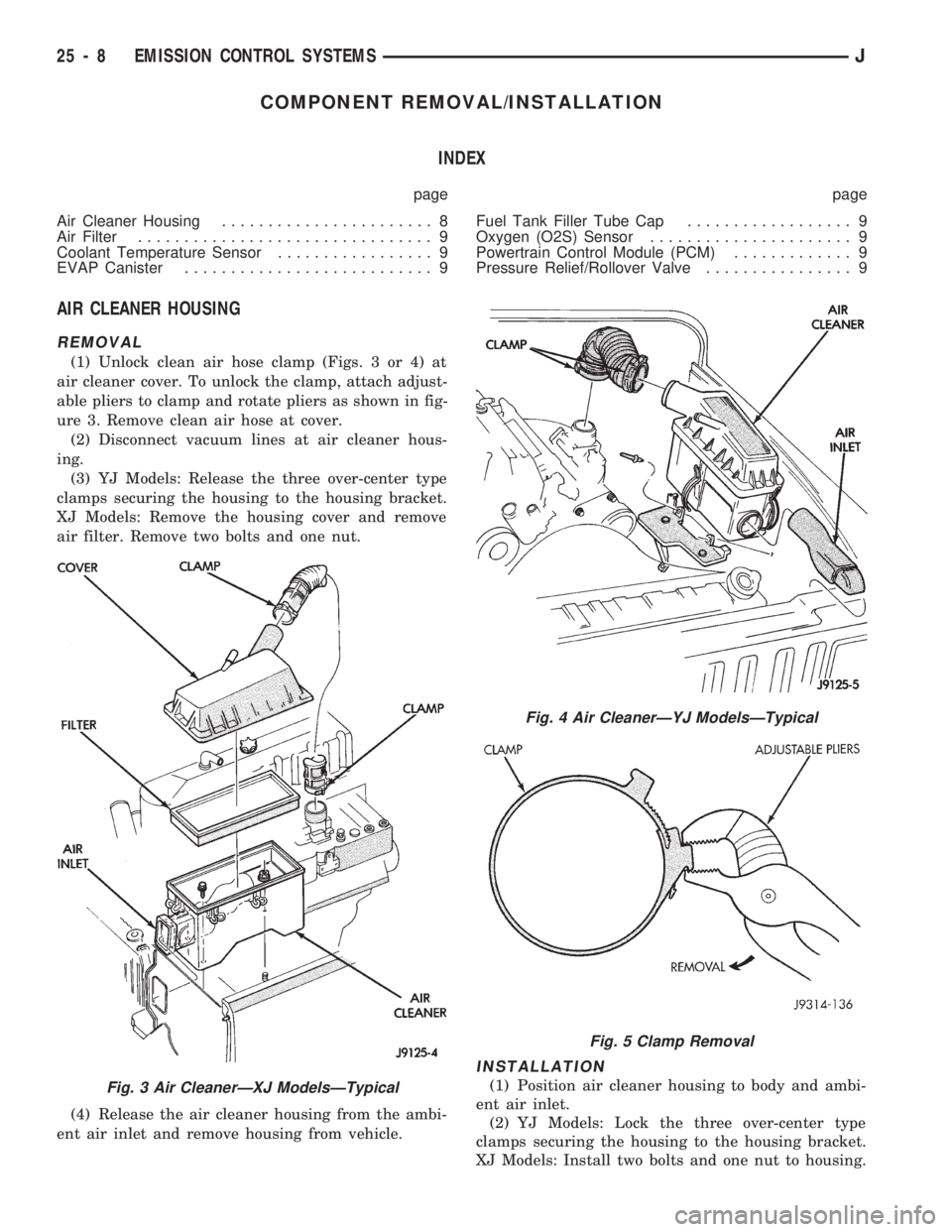
(1) Unlock clean air hose clamp (Figs. 3 or 4) at
air cleaner cover. To unlock the clamp, attach adjust-
able pliers to clamp and rotate pliers as shown in fig-
ure 3. Remove clean air hose at cover.
(2) Disconnect vacuum lines at air cleaner hous-
ing.
(3) YJ Models: Release the three over-center type
clamps securing the housing to the housing bracket.
XJ Models: Remove the housing cover and remove
air filter. Remove two bolts and one nut.
(4) Release the air cleaner housing from the ambi-
ent air inlet and remove housing from vehicle.
INSTALLATION
(1) Position air cleaner housing to body and ambi-
ent air inlet.
(2) YJ Models: Lock the three over-center type
clamps securing the housing to the housing bracket.
XJ Models: Install two bolts and one nut to housing.Fig. 3 Air CleanerÐXJ ModelsÐTypical
Fig. 4 Air CleanerÐYJ ModelsÐTypical
Fig. 5 Clamp Removal
25 - 8 EMISSION CONTROL SYSTEMSJ