change time JEEP CHEROKEE 1994 Service User Guide
[x] Cancel search | Manufacturer: JEEP, Model Year: 1994, Model line: CHEROKEE, Model: JEEP CHEROKEE 1994Pages: 1784, PDF Size: 77.09 MB
Page 29 of 1784
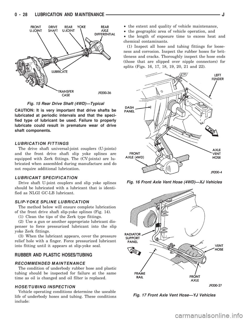
CAUTION: It is very important that drive shafts be
lubricated at periodic intervals and that the speci-
fied type of lubricant be used. Failure to properly
lubricate could result in premature wear of drive
shaft components.
LUBRICATION FITTINGS
The drive shaft universal-joint couplers (U-joints)
and the front drive shaft slip yoke splines are
equipped with Zerk fittings. The (CV-joints) are lu-
bricated when assembled during manufacture and do
not require additional lubrication.
LUBRICANT SPECIFICATION
Drive shaft U-joint couplers and slip yoke splines
should be lubricated with a lubricant that is identi-
fied as NLGI GC-LB lubricant.
SLIP-YOKE SPLINE LUBRICATION
The method below will ensure complete lubrication
of the front drive shaft slip-yoke splines (Fig. 14).
(1) Clean the tips of the Zerk type fittings.
(2) Use a gun or another appropriate lubricant dis-
penser to force pressurized lubricant into the slip
yoke Zerk fittings.
(3) When the lubricant appears, cover the pressure
relief hole with a finger. Force pressurized lubricant
into fitting until it appears at slip-yoke seal.
RUBBER AND PLASTIC HOSES/TUBING
RECOMMENDED MAINTENANCE
The condition of underbody rubber hose and plastic
tubing should be inspected for failure at the same
time as oil is changed and oil filter is replaced.
HOSE/TUBING INSPECTION
Vehicle operating conditions determine the useable
life of underbody hoses and tubing. These conditions
include:²the extent and quality of vehicle maintenance,
²the geographic area of vehicle operation, and
²the length of exposure time to excess heat and
chemical contaminants.
(1) Inspect all hose and tubing fittings for loose-
ness and corrosion. Inspect the rubber hoses for brit-
tleness and cracks. Thoroughly inspect the hose ends
(those that are slipped over nipple connectors) for
splits (Figs. 16, 17, 18, 19, 20, 21 and 22).
Fig. 16 Front Axle Vent Hose (4WD)ÐXJ Vehicles
Fig. 17 Front Axle Vent HoseÐYJ Vehicles
Fig. 15 Rear Drive Shaft (4WD)ÐTypical
0 - 28 LUBRICATION AND MAINTENANCEJ
Page 33 of 1784
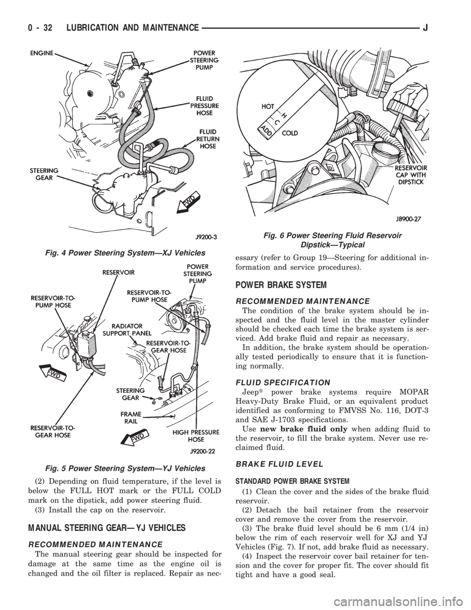
(2) Depending on fluid temperature, if the level is
below the FULL HOT mark or the FULL COLD
mark on the dipstick, add power steering fluid.
(3) Install the cap on the reservoir.
MANUAL STEERING GEARÐYJ VEHICLES
RECOMMENDED MAINTENANCE
The manual steering gear should be inspected for
damage at the same time as the engine oil is
changed and the oil filter is replaced. Repair as nec-essary (refer to Group 19ÐSteering for additional in-
formation and service procedures).
POWER BRAKE SYSTEM
RECOMMENDED MAINTENANCE
The condition of the brake system should be in-
spected and the fluid level in the master cylinder
should be checked each time the brake system is ser-
viced. Add brake fluid and repair as necessary.
In addition, the brake system should be operation-
ally tested periodically to ensure that it is function-
ing normally.
FLUID SPECIFICATION
Jeeptpower brake systems require MOPAR
Heavy-Duty Brake Fluid, or an equivalent product
identified as conforming to FMVSS No. 116, DOT-3
and SAE J-1703 specifications.
Usenew brake fluid onlywhen adding fluid to
the reservoir, to fill the brake system. Never use re-
claimed fluid.
BRAKE FLUID LEVEL
STANDARD POWER BRAKE SYSTEM
(1) Clean the cover and the sides of the brake fluid
reservoir.
(2) Detach the bail retainer from the reservoir
cover and remove the cover from the reservoir.
(3) The brake fluid level should be 6 mm (1/4 in)
below the rim of each reservoir well for XJ and YJ
Vehicles (Fig. 7). If not, add brake fluid as necessary.
(4) Inspect the reservoir cover bail retainer for ten-
sion and the cover for proper fit. The cover should fit
tight and have a good seal.
Fig. 4 Power Steering SystemÐXJ Vehicles
Fig. 5 Power Steering SystemÐYJ Vehicles
Fig. 6 Power Steering Fluid Reservoir
DipstickÐTypical
0 - 32 LUBRICATION AND MAINTENANCEJ
Page 35 of 1784
(6) Inspect the disc brake caliper dust boot for cor-
rect installation, damage/tears and indications of
brake fluid leakage. Inspect the bushings and pins
for corrosion, tears and a binding condition.
(7) Pull the rear wheel cylinder dust boot back to
expose the wheel cylinder housing and inspect for
fluid leaks. Inspect the pistons and cylinder bores for
proper appearance.
(8) Inspect the brake differential warning valve
and housing for indications of leakage, kinked hoses
and loose fittings.
PARK BRAKE
(1) As applicable, engage the park brake lever or
pedal and then release it.
(2) If the park brake is functioning normally, test
it for smooth operation and vehicle-holding capabil-
ity.
(3) Inspect the park brake cables for kinks, fraying
and a binding condition.
(4) With the park brake released, the rear wheels
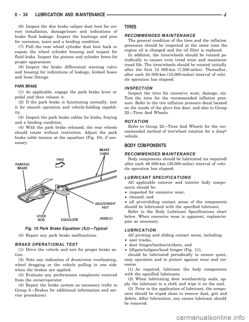
should rotate without restriction. Adjust the park
brake cable tension at the equalizer (Fig. 10), if nec-
essary.
(5) Repair any park brake malfunctions.
BRAKE OPERATIONAL TEST
(1) Drive the vehicle and test for proper brake ac-
tion.
(2) Note any indication of drum/rotor overheating,
wheel dragging or the vehicle pulling to one side
when the brakes are applied.
(3) Evaluate any performance complaints received
from the owner/operator.
(4) Repair the brake system as necessary (refer to
Group 5ÐBrakes for additional information and ser-
vice procedures).
TIRES
RECOMMENDED MAINTENANCE
The general condition of the tires and the inflation
pressures should be inspected at the same time the
engine oil is changed and the oil filter is replaced.
In addition, the tires/wheels should be rotated pe-
riodically to ensure even tread wear and maximum
tread life. The tires/wheels should be rotated initially
after the first 12 000-km (7,500-miles). Thereafter,
after each 24 000-km (15,000-miles) interval of vehi-
cle operation has elapsed.
INSPECTION
Inspect the tires for excessive wear, damage, etc.
Test the tires for the recommended inflation pres-
sure. Refer to the tire inflation pressure decal located
on the inside of the glove box door, and also to Group
22ÐTires And Wheels.
ROTATION
Refer to Group 22ÐTires And Wheels for the rec-
ommended method of tire/wheel rotation for a Jeept
vehicle.
BODY COMPONENTS
RECOMMENDED MAINTENANCE
Body components should be lubricated (as required)
after each 48 000-km (30,000-miles) interval of vehi-
cle operation has elapsed.
LUBRICANT SPECIFICATIONS
All applicable exterior and interior body compo-
nents should be:
²inspected for excessive wear,
²cleaned, and
²all pivot/sliding contact areas of the components
should be lubricated with the specified lubricant.
Refer to the Body Lubricant Specifications chart
below. When excessive wear is apparent, replace/re-
pair as necessary.
LUBRICATION
All pivoting and sliding contact areas, including:
²seat tracks,
²door hinges/latches/strikers, and
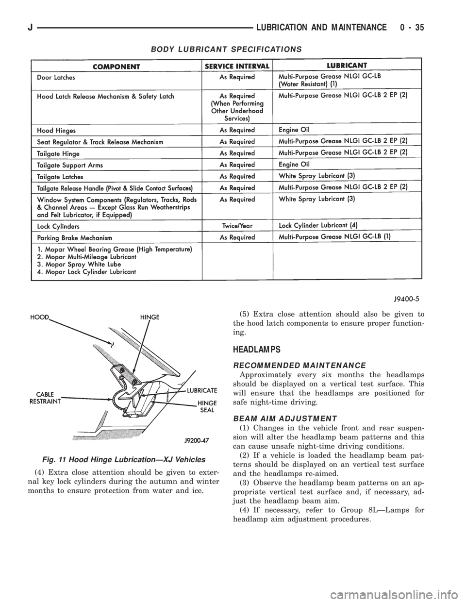
²liftgate/tailgate/hood hinges (Fig. 11),
should be lubricated periodically to ensure quiet,
easy operation and to protect against wear and cor-
rosion.
(1) As required, lubricate the body components
with the specified lubricants.
(2) When lubricating door weatherstrip seals, ap-
ply the lubricant to a cloth and wipe it on the seal.
(3) Prior to the application of lubricant, the compo-
nent should be wiped clean to remove dust, grit and
debris. After lubrication, any excess lubricant should
be removed.
Fig. 10 Park Brake Equalizer (XJ)ÐTypical
0 - 34 LUBRICATION AND MAINTENANCEJ
Page 36 of 1784
(4) Extra close attention should be given to exter-
nal key lock cylinders during the autumn and winter
months to ensure protection from water and ice.(5) Extra close attention should also be given to
the hood latch components to ensure proper function-
ing.
HEADLAMPS
RECOMMENDED MAINTENANCE
Approximately every six months the headlamps
should be displayed on a vertical test surface. This
will ensure that the headlamps are positioned for
safe night-time driving.
BEAM AIM ADJUSTMENT
(1) Changes in the vehicle front and rear suspen-
sion will alter the headlamp beam patterns and this
can cause unsafe night-time driving conditions.
(2) If a vehicle is loaded the headlamp beam pat-
terns should be displayed on an vertical test surface
and the headlamps re-aimed.
(3) Observe the headlamp beam patterns on an ap-
propriate vertical test surface and, if necessary, ad-
just the headlamp beam aim.
(4) If necessary, refer to Group 8LÐLamps for
headlamp aim adjustment procedures.
BODY LUBRICANT SPECIFICATIONS
Fig. 11 Hood Hinge LubricationÐXJ Vehicles
JLUBRICATION AND MAINTENANCE 0 - 35
Page 43 of 1784
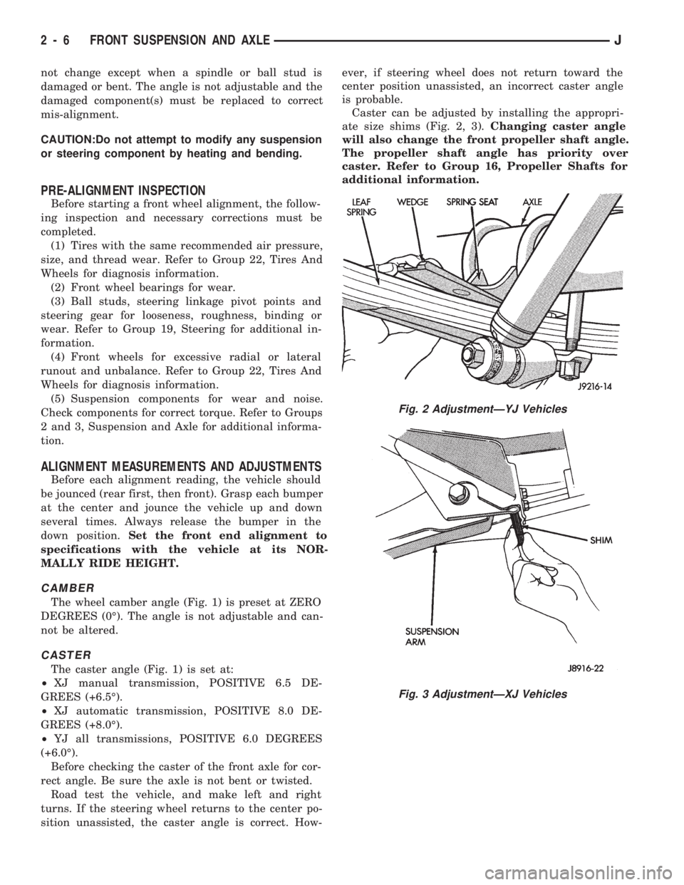
not change except when a spindle or ball stud is
damaged or bent. The angle is not adjustable and the
damaged component(s) must be replaced to correct
mis-alignment.
CAUTION:Do not attempt to modify any suspension
or steering component by heating and bending.
PRE-ALIGNMENT INSPECTION
Before starting a front wheel alignment, the follow-
ing inspection and necessary corrections must be
completed.
(1) Tires with the same recommended air pressure,
size, and thread wear. Refer to Group 22, Tires And
Wheels for diagnosis information.
(2) Front wheel bearings for wear.
(3) Ball studs, steering linkage pivot points and
steering gear for looseness, roughness, binding or
wear. Refer to Group 19, Steering for additional in-
formation.
(4) Front wheels for excessive radial or lateral
runout and unbalance. Refer to Group 22, Tires And
Wheels for diagnosis information.
(5) Suspension components for wear and noise.
Check components for correct torque. Refer to Groups
2 and 3, Suspension and Axle for additional informa-
tion.
ALIGNMENT MEASUREMENTS AND ADJUSTMENTS
Before each alignment reading, the vehicle should
be jounced (rear first, then front). Grasp each bumper
at the center and jounce the vehicle up and down
several times. Always release the bumper in the
down position.Set the front end alignment to
specifications with the vehicle at its NOR-
MALLY RIDE HEIGHT.
CAMBER
The wheel camber angle (Fig. 1) is preset at ZERO
DEGREES (0É). The angle is not adjustable and can-
not be altered.
CASTER
The caster angle (Fig. 1) is set at:
²XJ manual transmission, POSITIVE 6.5 DE-
GREES (+6.5É).
²XJ automatic transmission, POSITIVE 8.0 DE-
GREES (+8.0É).
²YJ all transmissions, POSITIVE 6.0 DEGREES
(+6.0É).
Before checking the caster of the front axle for cor-
rect angle. Be sure the axle is not bent or twisted.
Road test the vehicle, and make left and right
turns. If the steering wheel returns to the center po-
sition unassisted, the caster angle is correct. How-ever, if steering wheel does not return toward the
center position unassisted, an incorrect caster angle
is probable.
Caster can be adjusted by installing the appropri-
ate size shims (Fig. 2, 3).Changing caster angle
will also change the front propeller shaft angle.
The propeller shaft angle has priority over
caster. Refer to Group 16, Propeller Shafts for
additional information.
Fig. 2 AdjustmentÐYJ Vehicles
Fig. 3 AdjustmentÐXJ Vehicles
2 - 6 FRONT SUSPENSION AND AXLEJ
Page 59 of 1784
(9) Disconnect the tie rod from the steering
knuckle. Disconnect the steering dampener from the
axle bracket.
(10) Support the axle with a hydraulic jack under
the differential. Raise the axle just enough to relieve
the axle weight from the springs.
(11) Remove the spring U-bolts from the plate
brackets.
(12) Loosen BUT DO NOT REMOVE the bolts that
attach the spring rear pivot at the frame rail brack-
ets. This will allow the springs to pivot without bind-
ing on the bushings.
(13) Disconnect shackle from the springs and lower
the springs to the surface.
(14) Lower the jack enough to remove the axle.
INSTALLATION
CAUTION: All suspension components that use rub-
ber bushings should be tightened with the vehicle
at the normal height. It is important to have the
springs supporting the weight of the vehicle when
the fasteners are torqued. If the springs are not at
their normal ride position, vehicle ride comfort
could be affected along with premature rubber
bushing wear. Rubber bushings must never be lu-
bricated.
(1) Support the axle on a hydraulic jack under the
differential. Position the axle under the vehicle.
(2) Raise the springs and install the spring shackle
bolts.Do not tighten at this time.
(3) Lower the axle and align the spring center
bolts with the locating holes in the axle pads and
plate brackets.
(4) Install the spring U-bolts through the plate
brackets and tighten to 122 Nzm (90 ft. lbs.) torque.
(5) Connect the track bar to the axle bracket and
install the bolt.Do not tighten at this time.
It is important that the springs support the
weight of the vehicle when the track bar is con-
nected. If the springs are not at their usual po-
sition, the vehicle ride comfort could be affected.
(6) Install the shock absorber and tighten the nut
to 61 Nzm (45 ft. lbs.) torque.
(7) Install the stabilizer bar link to the axle
bracket. Tighten the nut to 61 Nzm (45 ft. lbs.)
torque.
(8) Install the tie rod to the steering knuckles and
tighten the nuts to 47 Nzm (35 ft. lbs.) torque. Install
the steering dampener to the axle bracket and
tighten the bolt to 75 Nzm (55 ft. lbs.) torque.
(9) Install the brake components and ABS brake
sensor (if equipped). Refer to Group 5ÐBrakes.
(10) Connect the vent hose to the tube fitting and
axle shift motor vacuum harness.(11) Align the reference marks and connect the
drive shaft to the axle yoke. Tighten the U-joint
clamp bolts to 19 Nzm (14 ft. lbs.) torque.
(12) Check differential lubricant and add if neces-
sary.
(13) Install the wheel and tire assemblies.
(14) Remove the supports and lower the vehicle.
(15) Tighten the spring rear pivot bolt/nut to 142
Nzm (105 ft. lbs.) torque. Tighten the spring shackle
bolt/nut to 135 Nzm (100 ft. lbs.) torque.
(16) Tighten the track bar nut at the axle bracket
to 100 Nzm (74 ft. lbs.) torque.
(17) Check the front wheel alignment.
LUBRICANT CHANGE
The gear lubricant will drain quicker if the vehicle
has been recently driven.
(1) Raise and support the vehicle.
(2) Remove the lubricant fill hole plug from the
differential housing cover.
(3) Remove the differential housing cover and
drain the lubricant from the housing.
(4) Clean the housing cavity with a flushing oil,
light engine oil or lint free cloth.Do not use water,
steam, kerosene or gasoline for cleaning.
(5) Remove the sealant from the housing and cover
surfaces. Use solvent to clean the mating surfaces.
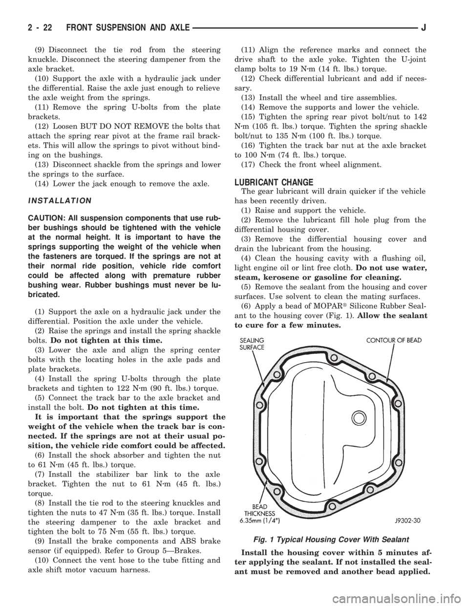
(6) Apply a bead of MOPARtSilicone Rubber Seal-
ant to the housing cover (Fig. 1).Allow the sealant
to cure for a few minutes.
Install the housing cover within 5 minutes af-
ter applying the sealant. If not installed the seal-
ant must be removed and another bead applied.
Fig. 1 Typical Housing Cover With Sealant
2 - 22 FRONT SUSPENSION AND AXLEJ
Page 136 of 1784

DRB SCAN TOOL
For operation of the DRB scan tool, refer to the ap-
propriate Powertrain Diagnostic Procedures service
manual.
DIAGNOSTIC TROUBLE CODE (DTC)
On the following pages, a list of diagnostic trouble
codes is provided for the 2.5L 4 cylinder and 4.0L 6
cylinder engines. A DTC indicates that the power-
train control module (PCM) has recognized an abnor-
mal signal in a circuit or the system. A DTC may
indicate the result of a failure, but never identify the
failed component directly.
DIAGNOSTIC TROUBLE CODE DESCRIPTIONS
Diagnostic
Trouble
CodeDRB Scan Tool
DisplayDescription of Diagnostic Trouble Code
11* .......... NoCrank Reference
Signal at PCMNo crank reference signal detected during engine cranking.
12* ..........Battery Disconnect Direct battery input to PCM was disconnected within the last 50 Key-on
cycles.
13**.......... NoChange in MAP From
Start to RunNo difference recognized between the engine MAP reading and the
barometric (atmospheric) pressure reading at start-up.
14**.......... MAPSensor Voltage Too
LowMAP sensor input below minimum acceptable voltage.
or
MAP Sensor Voltage Too
HighMAP sensor input above maximum acceptable voltage.
15**.......... NoVehicle Speed Sensor
SignalNo vehicle distance (speed) sensor signal detected during road load
conditions.
17* ..........Engine is Cold Too Long Engine coolant temperature remains below normal operating temperatures
during vehicle travel (thermostat).
21**.......... O2SStays at Center Neither rich or lean condition detected from the oxygen sensor input.
or
O2S Shorted to Voltage Oxygen sensor input voltage maintained above the normal operating range.
22**.......... ECTSensor Voltage Too
HighEngine coolant temperature sensor input above maximum acceptable
voltage.
or
ECT Sensor Voltage Too
LowEngine coolant temperature sensor input below minimum acceptable voltage.
* Check Engine Lamp will not illuminate at all times if this Diagnostic Trouble Code was recorded. Cycle Ignition key as
described in manual and observe code flashed by Check Engine lamp.
** Check Engine Lamp will illuminate during engine operation if this Diagnostic Trouble Code was recorded.
Fig. 47 Data Link Connector Schematic
JFUEL SYSTEM 14 - 51
Page 138 of 1784
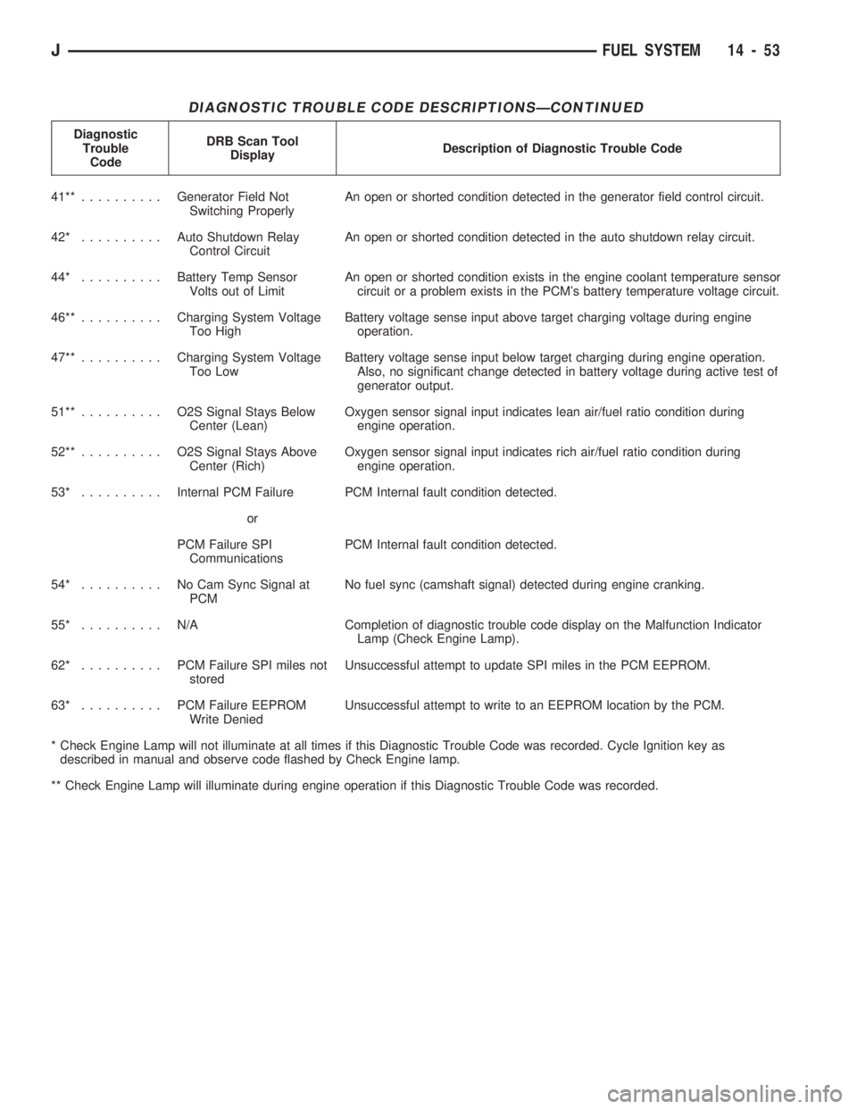
DIAGNOSTIC TROUBLE CODE DESCRIPTIONSÐCONTINUED
Diagnostic
Trouble
CodeDRB Scan Tool
DisplayDescription of Diagnostic Trouble Code
41**..........Generator Field Not
Switching ProperlyAn open or shorted condition detected in the generator field control circuit.
42* ..........Auto Shutdown Relay
Control CircuitAn open or shorted condition detected in the auto shutdown relay circuit.
44* ..........Battery Temp Sensor
Volts out of LimitAn open or shorted condition exists in the engine coolant temperature sensor
circuit or a problem exists in the PCM's battery temperature voltage circuit.
46**..........Charging System Voltage
Too HighBattery voltage sense input above target charging voltage during engine
operation.
47**..........Charging System Voltage
Too LowBattery voltage sense input below target charging during engine operation.
Also, no significant change detected in battery voltage during active test of
generator output.
51**.......... O2SSignal Stays Below
Center (Lean)Oxygen sensor signal input indicates lean air/fuel ratio condition during
engine operation.
52**.......... O2SSignal Stays Above
Center (Rich)Oxygen sensor signal input indicates rich air/fuel ratio condition during
engine operation.
53* ..........Internal PCM Failure PCM Internal fault condition detected.
or
PCM Failure SPI
CommunicationsPCM Internal fault condition detected.
54* .......... NoCamSync Signal at
PCMNo fuel sync (camshaft signal) detected during engine cranking.
55* .......... N/ACompletion of diagnostic trouble code display on the Malfunction Indicator
Lamp (Check Engine Lamp).
62* .......... PCMFailure SPI miles not
storedUnsuccessful attempt to update SPI miles in the PCM EEPROM.
63* .......... PCMFailure EEPROM
Write DeniedUnsuccessful attempt to write to an EEPROM location by the PCM.
* Check Engine Lamp will not illuminate at all times if this Diagnostic Trouble Code was recorded. Cycle Ignition key as
described in manual and observe code flashed by Check Engine lamp.
** Check Engine Lamp will illuminate during engine operation if this Diagnostic Trouble Code was recorded.
JFUEL SYSTEM 14 - 53
Page 156 of 1784
Brake drag also has a direct effect on fuel economy.
If undetected, minor brake drag can be misdiagnosed
as an engine or transmission/torque converter prob-
lem.
Minor drag will usually cause slight surface char-
ring of the lining. It can also generate hard spots in
rotors and drums from the overheat/cool down pro-
cess. In most cases, the rotors, drums, wheels and
tires are quite warm to the touch after the vehicle is
stopped.
Severe drag can char the brake lining all the way
through. It can also distort and score rotors and
drums to the point of replacement. The wheels, tires
and brake components will be extremely hot. In se-
vere cases, the lining may generate smoke as it chars
from overheating.
An additional cause of drag involves the use of in-
correct length caliper mounting bolts. Bolts that are
too long can cause a partial apply condition. The cor-
rect caliper bolts have a shank length of 67 mm
(2.637 in.), plus or minus 0.6 mm (0.0236 in.). Refer
to the Disc Brake service section for more detail on
caliper bolt dimensions and identification.
Some common causes of brake drag are:
²loose or damaged wheel bearing
²seized or sticking caliper or wheel cylinder piston
²caliper binding on bushings or slide surfaces
²wrong length caliper mounting bolts (too long)
²loose caliper mounting bracket
²distorted brake drum or shoes
²rear brakeshoes binding on worn/damaged support
plates
²severely rusted/corroded components
²misassembled components.
If brake drag occurs at all wheels, the problem may
be related to a blocked master cylinder compensator
port or faulty power booster (binds-does not release).
The brakelight switch can also be a cause of drag.
An improperly mounted or adjusted brakelight
switch can prevent full brake pedal return. The re-
sult will be the same as if the master cylinder com-
pensator ports are blocked. The brakes would be
partially applied causing drag.
BRAKE FADE
Brake fade is a product of overheating caused by
brake drag. However, overheating and subsequent
fade can also be caused by riding the brake pedal,
making repeated high deceleration stops in a short
time span, or constant braking on steep roads. Refer
to the Brake Drag information in this section for
causes.
PEDAL PULSATION
Pedal pulsation is caused by components that are
loose, or beyond tolerance limits.
Disc brake rotors with excessive lateral runout or
thickness variation, or out of round brake drums arethe primary causes of pulsation. Other causes are
loose wheel bearings or calipers and worn, damaged
tires.
PULL
A front pull condition could be the result of:
²contaminated lining in one caliper
²seized caliper piston
²binding caliper
²wrong caliper mounting bolts (too long)
²loose caliper
²loose or corroded mounting bolts
²improper brakeshoes
²damaged rotor
²incorrect wheel bearing adjustment (at one wheel)
A worn, damaged wheel bearing or suspension
component are further causes of pull. A damaged
front tire (bruised, ply separation) can also cause
pull. Wrong caliper bolts (too long) will cause a par-
tial apply condition and pull if only one caliper is in-
volved.
A common and frequently misdiagnosed pull condi-
tion is where direction of pull changes after a few
stops. The cause is a combination of brake drag fol-
lowed by fade at the dragging brake unit.
As the dragging brake overheats, efficiency is so
reduced that fade occurs. If the opposite brake unit is
still functioning normally, its braking effect is mag-
nified. This causes pull to switch direction in favor of
the brake unit that is functioning normally.
When diagnosing a change in pull condition, re-
member that pull will return to the original direction
if the dragging brake unit is allowed to cool down
(and is not seriously damaged).
REAR BRAKE GRAB
Rear grab (or pull) is usually caused by contami-
nated lining, bent or binding shoes and support
plates, or improperly assembled components. This is
particularly true when only one rear wheel is in-
volved. However, when both rear wheels are affected,
the master cylinder or proportioning valve could be
at fault.
BRAKES DO NOT HOLD AFTER DRIVING
THROUGH DEEP WATER PUDDLES
This condition is generally caused by water soaked
lining. If the lining is only wet, it can be dried by
driving with the brakes lightly applied for a mile or
two. However, if the lining is both wet and dirty, dis-
assembly and cleaning will be necessary.
BRAKE FLUID CONTAMINATION
There are two basic causes of brake fluid contami-
nation. The first involves allowing dirt, debris, or
other liquid materials to enter the cylinder reservoirs
JBRAKES 5 - 9
Page 176 of 1784
Do not hone the caliper piston bore. Replace the cal-
iper if the bore exhibits any of the aforementioned
conditions.
Inspect the caliper piston. The piston is made from
a phenolic resin (plastic material) and should be
smooth and clean. Replace the piston if cracked,
chipped, or scored. Do not attempt to restore a
scored, or corroded piston surface by sanding or pol-
ishing. The piston must be replaced if damaged.
CAUTION: Never interchange phenolic resin and
steel caliper pistons. The seals, seal grooves, cali-
per bores and piston tolerances are different for
resin and steel pistons. Do not intermix these com-
ponents.
Inspect the caliper mounting bolt bushings and
boots. Replace the boots if cut or torn. Clean and lu-
bricate the bushings with GE 661 or Dow 111 sili-
cone grease if necessary.
Inspect condition of the caliper mounting bolts. Re-
place the bolts if corroded, rusted, or worn. Do not re-
use the bolts if unsure of their condition.
Length of the caliper mounting bolts is also ex-
tremely important.
Use the replacement bolts specified in the parts
catalog at all times. Do not use substitute bolts.
Bolts that are too long will partially apply the in-
board brakeshoe causing drag and pull. Refer to the
caliper and brakeshoe installation procedures for ser-
vice details and bolt dimensions.
CALIPER ASSEMBLY
(1) Coat caliper piston bore, new piston seal and
piston with clean, fresh brake fluid.
(2) Lubricate caliper bushings and interior of bush-
ing boots with GE 661, Dow 111, or Permatex Dielec-
tric silicone grease.
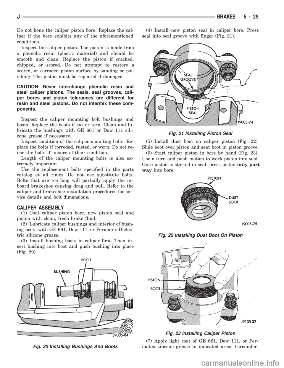
(3) Install bushing boots in caliper first. Then in-
sert bushing into boot and push bushing into place
(Fig. 20).(4) Install new piston seal in caliper bore. Press
seal into seal groove with finger (Fig. 21).
(5) Install dust boot on caliper piston (Fig. 22).
Slide boot over piston and seat boot in piston groove.
(6) Start caliper piston in bore by hand (Fig. 23).
Use a turn and push motion to work piston into seal.
Once piston is started in seal, press pistononly part
wayinto bore.
(7) Apply light coat of GE 661, Dow 111, or Per-
matex silicone grease to indicated areas (circumfer-
Fig. 20 Installing Bushings And Boots
Fig. 21 Installing Piston Seal
Fig. 22 Installing Dust Boot On Piston
Fig. 23 Installing Caliper Piston
JBRAKES 5 - 29