dash JEEP CHEROKEE 1994 Service User Guide
[x] Cancel search | Manufacturer: JEEP, Model Year: 1994, Model line: CHEROKEE, Model: JEEP CHEROKEE 1994Pages: 1784, PDF Size: 77.09 MB
Page 208 of 1784
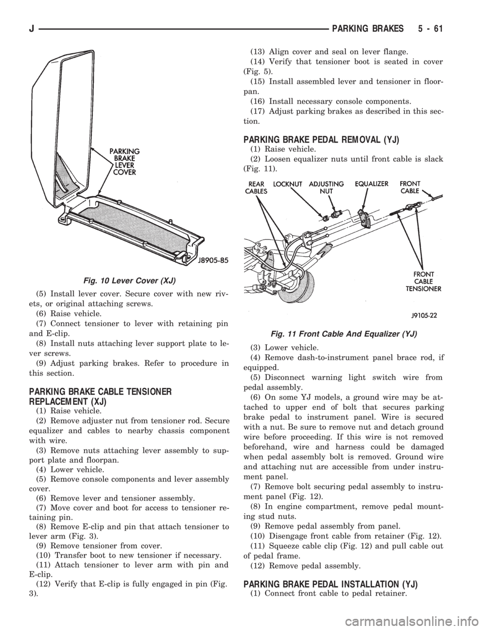
(5) Install lever cover. Secure cover with new riv-
ets, or original attaching screws.
(6) Raise vehicle.
(7) Connect tensioner to lever with retaining pin
and E-clip.
(8) Install nuts attaching lever support plate to le-
ver screws.
(9) Adjust parking brakes. Refer to procedure in
this section.
PARKING BRAKE CABLE TENSIONER
REPLACEMENT (XJ)
(1) Raise vehicle.
(2) Remove adjuster nut from tensioner rod. Secure
equalizer and cables to nearby chassis component
with wire.
(3) Remove nuts attaching lever assembly to sup-
port plate and floorpan.
(4) Lower vehicle.
(5) Remove console components and lever assembly
cover.
(6) Remove lever and tensioner assembly.
(7) Move cover and boot for access to tensioner re-
taining pin.
(8) Remove E-clip and pin that attach tensioner to
lever arm (Fig. 3).
(9) Remove tensioner from cover.
(10) Transfer boot to new tensioner if necessary.
(11) Attach tensioner to lever arm with pin and
E-clip.
(12) Verify that E-clip is fully engaged in pin (Fig.
3).(13) Align cover and seal on lever flange.
(14) Verify that tensioner boot is seated in cover
(Fig. 5).
(15) Install assembled lever and tensioner in floor-
pan.
(16) Install necessary console components.
(17) Adjust parking brakes as described in this sec-
tion.
PARKING BRAKE PEDAL REMOVAL (YJ)
(1) Raise vehicle.
(2) Loosen equalizer nuts until front cable is slack
(Fig. 11).
(3) Lower vehicle.
(4) Remove dash-to-instrument panel brace rod, if
equipped.
(5) Disconnect warning light switch wire from
pedal assembly.
(6) On some YJ models, a ground wire may be at-
tached to upper end of bolt that secures parking
brake pedal to instrument panel. Wire is secured
with a nut. Be sure to remove nut and detach ground
wire before proceeding. If this wire is not removed
beforehand, wire and harness could be damaged
when pedal assembly bolt is removed. Ground wire
and attaching nut are accessible from under instru-
ment panel.
(7) Remove bolt securing pedal assembly to instru-
ment panel (Fig. 12).
(8) In engine compartment, remove pedal mount-
ing stud nuts.
(9) Remove pedal assembly from panel.
(10) Disengage front cable from retainer (Fig. 12).
(11) Squeeze cable clip (Fig. 12) and pull cable out
of pedal frame.
(12) Remove pedal assembly.
PARKING BRAKE PEDAL INSTALLATION (YJ)
(1) Connect front cable to pedal retainer.
Fig. 10 Lever Cover (XJ)
Fig. 11 Front Cable And Equalizer (YJ)
JPARKING BRAKES 5 - 61
Page 209 of 1784
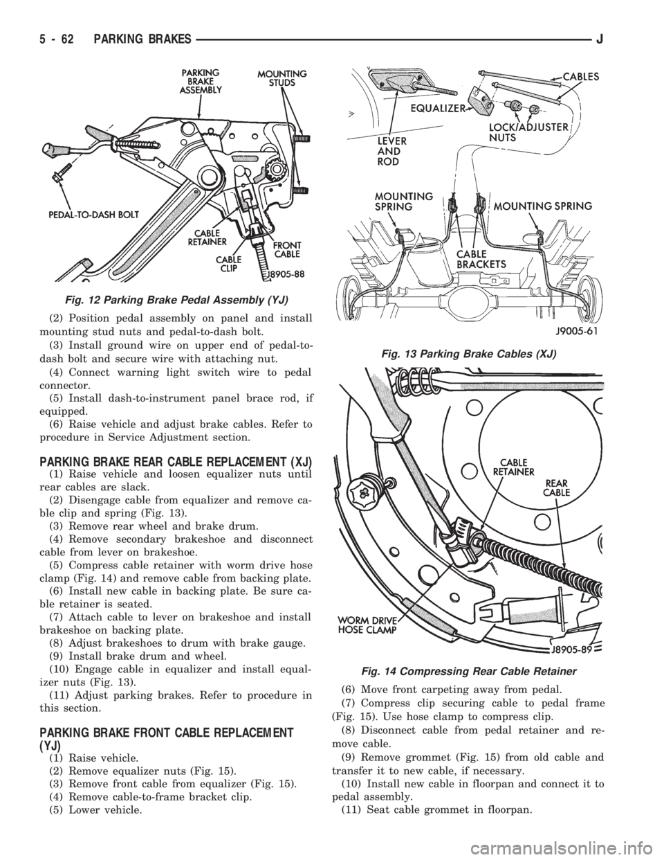
(2) Position pedal assembly on panel and install
mounting stud nuts and pedal-to-dash bolt.
(3) Install ground wire on upper end of pedal-to-
dash bolt and secure wire with attaching nut.
(4) Connect warning light switch wire to pedal
connector.
(5) Install dash-to-instrument panel brace rod, if
equipped.
(6) Raise vehicle and adjust brake cables. Refer to
procedure in Service Adjustment section.
PARKING BRAKE REAR CABLE REPLACEMENT (XJ)
(1) Raise vehicle and loosen equalizer nuts until
rear cables are slack.
(2) Disengage cable from equalizer and remove ca-
ble clip and spring (Fig. 13).
(3) Remove rear wheel and brake drum.
(4) Remove secondary brakeshoe and disconnect
cable from lever on brakeshoe.
(5) Compress cable retainer with worm drive hose
clamp (Fig. 14) and remove cable from backing plate.
(6) Install new cable in backing plate. Be sure ca-
ble retainer is seated.
(7) Attach cable to lever on brakeshoe and install
brakeshoe on backing plate.
(8) Adjust brakeshoes to drum with brake gauge.
(9) Install brake drum and wheel.
(10) Engage cable in equalizer and install equal-
izer nuts (Fig. 13).
(11) Adjust parking brakes. Refer to procedure in
this section.
PARKING BRAKE FRONT CABLE REPLACEMENT
(YJ)
(1) Raise vehicle.
(2) Remove equalizer nuts (Fig. 15).
(3) Remove front cable from equalizer (Fig. 15).
(4) Remove cable-to-frame bracket clip.
(5) Lower vehicle.(6) Move front carpeting away from pedal.
(7) Compress clip securing cable to pedal frame
(Fig. 15). Use hose clamp to compress clip.
(8) Disconnect cable from pedal retainer and re-
move cable.
(9) Remove grommet (Fig. 15) from old cable and
transfer it to new cable, if necessary.
(10) Install new cable in floorpan and connect it to
pedal assembly.
(11) Seat cable grommet in floorpan.
Fig. 12 Parking Brake Pedal Assembly (YJ)
Fig. 13 Parking Brake Cables (XJ)
Fig. 14 Compressing Rear Cable Retainer
5 - 62 PARKING BRAKESJ
Page 212 of 1784
BRAKE PEDAL AND BRAKELIGHT SWITCH
INDEX
page page
Brake Pedal Installation.................... 66
Brake Pedal Removal..................... 65
Brake Pedal Service...................... 65
Brakelight Switch Adjustment................ 66Brakelight Switch Installation................ 66
Brakelight Switch Removal................. 66
General Information....................... 65
GENERAL INFORMATION
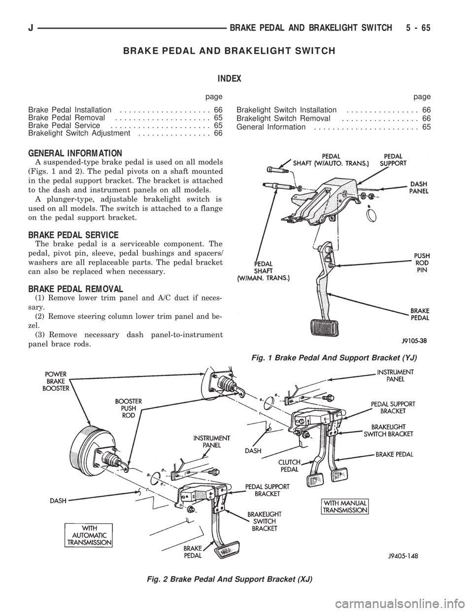
A suspended-type brake pedal is used on all models
(Figs. 1 and 2). The pedal pivots on a shaft mounted
in the pedal support bracket. The bracket is attached
to the dash and instrument panels on all models.
A plunger-type, adjustable brakelight switch is
used on all models. The switch is attached to a flange
on the pedal support bracket.
BRAKE PEDAL SERVICE
The brake pedal is a serviceable component. The
pedal, pivot pin, sleeve, pedal bushings and spacers/
washers are all replaceable parts. The pedal bracket
can also be replaced when necessary.
BRAKE PEDAL REMOVAL
(1) Remove lower trim panel and A/C duct if neces-
sary.
(2) Remove steering column lower trim panel and be-
zel.
(3) Remove necessary dash panel-to-instrument
panel brace rods.
Fig. 1 Brake Pedal And Support Bracket (YJ)
Fig. 2 Brake Pedal And Support Bracket (XJ)
JBRAKE PEDAL AND BRAKELIGHT SWITCH 5 - 65
Page 213 of 1784
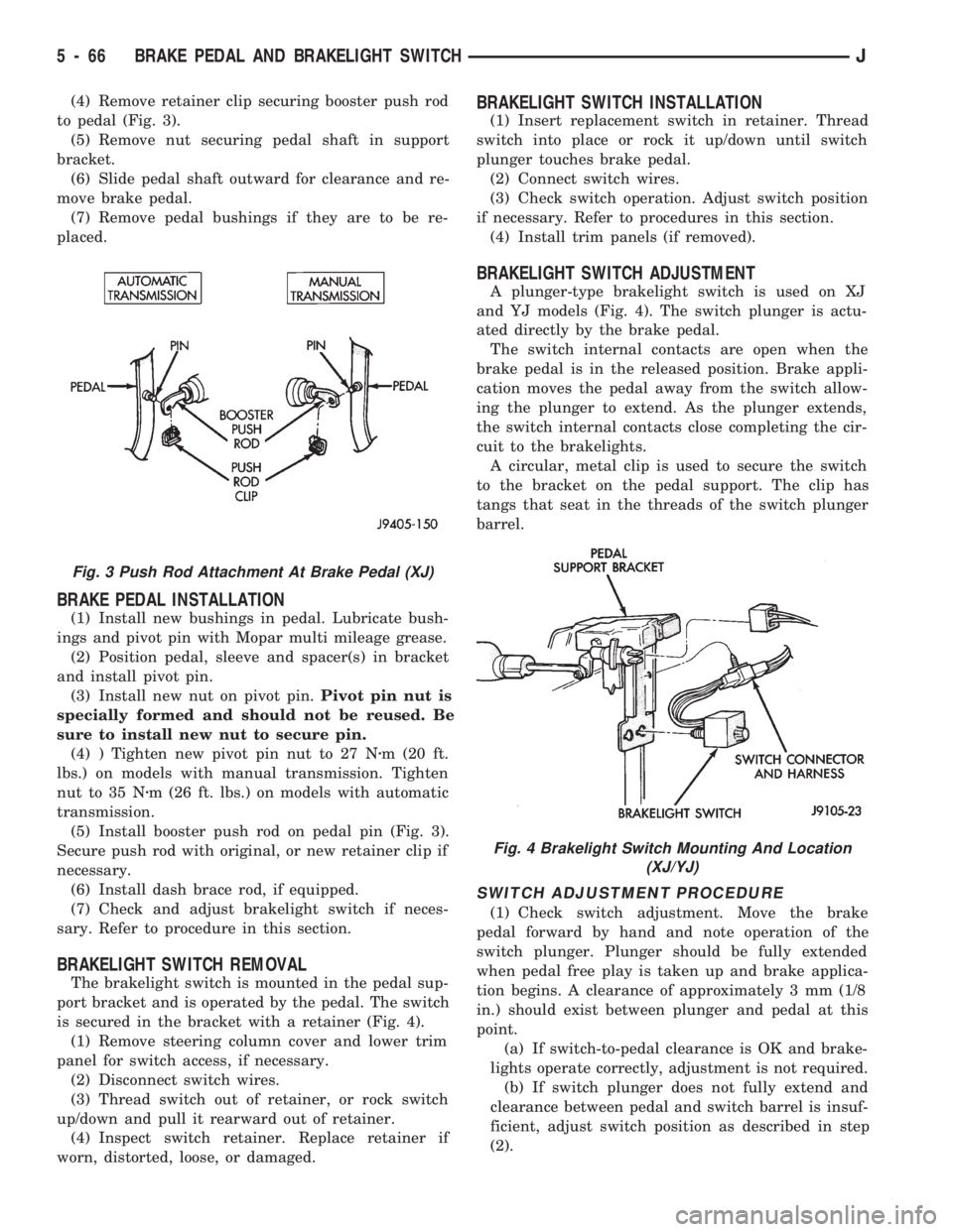
(4) Remove retainer clip securing booster push rod
to pedal (Fig. 3).
(5) Remove nut securing pedal shaft in support
bracket.
(6) Slide pedal shaft outward for clearance and re-
move brake pedal.
(7) Remove pedal bushings if they are to be re-
placed.
BRAKE PEDAL INSTALLATION
(1) Install new bushings in pedal. Lubricate bush-
ings and pivot pin with Mopar multi mileage grease.
(2) Position pedal, sleeve and spacer(s) in bracket
and install pivot pin.
(3) Install new nut on pivot pin.Pivot pin nut is
specially formed and should not be reused. Be
sure to install new nut to secure pin.
(4) ) Tighten new pivot pin nut to 27 Nzm (20 ft.
lbs.) on models with manual transmission. Tighten
nut to 35 Nzm (26 ft. lbs.) on models with automatic
transmission.
(5) Install booster push rod on pedal pin (Fig. 3).
Secure push rod with original, or new retainer clip if
necessary.
(6) Install dash brace rod, if equipped.
(7) Check and adjust brakelight switch if neces-
sary. Refer to procedure in this section.
BRAKELIGHT SWITCH REMOVAL
The brakelight switch is mounted in the pedal sup-
port bracket and is operated by the pedal. The switch
is secured in the bracket with a retainer (Fig. 4).
(1) Remove steering column cover and lower trim
panel for switch access, if necessary.
(2) Disconnect switch wires.
(3) Thread switch out of retainer, or rock switch
up/down and pull it rearward out of retainer.
(4) Inspect switch retainer. Replace retainer if
worn, distorted, loose, or damaged.
BRAKELIGHT SWITCH INSTALLATION
(1) Insert replacement switch in retainer. Thread
switch into place or rock it up/down until switch
plunger touches brake pedal.
(2) Connect switch wires.
(3) Check switch operation. Adjust switch position
if necessary. Refer to procedures in this section.
(4) Install trim panels (if removed).
BRAKELIGHT SWITCH ADJUSTMENT
A plunger-type brakelight switch is used on XJ
and YJ models (Fig. 4). The switch plunger is actu-
ated directly by the brake pedal.
The switch internal contacts are open when the
brake pedal is in the released position. Brake appli-
cation moves the pedal away from the switch allow-
ing the plunger to extend. As the plunger extends,
the switch internal contacts close completing the cir-
cuit to the brakelights.
A circular, metal clip is used to secure the switch
to the bracket on the pedal support. The clip has
tangs that seat in the threads of the switch plunger
barrel.
SWITCH ADJUSTMENT PROCEDURE
(1) Check switch adjustment. Move the brake
pedal forward by hand and note operation of the
switch plunger. Plunger should be fully extended
when pedal free play is taken up and brake applica-
tion begins. A clearance of approximately 3 mm (1/8
in.) should exist between plunger and pedal at this
point.
(a) If switch-to-pedal clearance is OK and brake-
lights operate correctly, adjustment is not required.
(b) If switch plunger does not fully extend and
clearance between pedal and switch barrel is insuf-
ficient, adjust switch position as described in step
(2).
Fig. 3 Push Rod Attachment At Brake Pedal (XJ)
Fig. 4 Brakelight Switch Mounting And Location
(XJ/YJ)
5 - 66 BRAKE PEDAL AND BRAKELIGHT SWITCHJ
Page 216 of 1784
CLUTCH
CONTENTS
page page
CLUTCH DIAGNOSIS..................... 3
CLUTCH SERVICE...................... 10GENERAL INFORMATION.................. 1
GENERAL INFORMATION
INDEX
page page
Clutch Component Lubrication................ 1
Clutch Components........................ 1Clutch Linkage Fluid....................... 1
Clutch Operation.......................... 2
CLUTCH COMPONENTS
MECHANICAL COMPONENTS
The clutch mechanism in XJ/YJ models with man-
ual transmission consists of a single, dry-type clutch
disc and a diaphragm style clutch cover. A hydraulic
linkage is used to operate the clutch disc and cover.
The transmission input shaft is supported in the
crankshaft by a bearing. A sleeve type release bear-
ing is used to engage and disengage the clutch cover
pressure plate.
The release bearing is operated by a release fork in
the clutch housing. The fork pivots on a ball stud
mounted inside the housing. The release fork is actu-
ated by a hydraulic slave cylinder mounted in the
housing. The slave cylinder is operated by a clutch
master cylinder mounted on the dash panel. The cyl-
inder push rod is connected to the clutch pedal.
The clutch disc has cushion springs in the disc hub.
The clutch disc facing is riveted to the hub. The fac-
ing is made from a non-asbestos material. The clutch
cover pressure plate is a diaphragm type with a one-
piece spring and multiple release fingers. The pres-
sure plate release fingers are preset during
manufacture and are not adjustable.
HYDRAULIC LINKAGE COMPONENTS
The hydraulic linkage consists of a clutch master
cylinder with integral reservoir, a clutch slave cylin-
der and an interconnecting fluid line.
The clutch master cylinder push rod is connected to
the clutch pedal. The slave cylinder push rod is con-
nected to the clutch release fork. The master cylinder
is mounted on the driver side of the dash panel ad-jacent to the brake master cylinder and booster as-
sembly. This positioning is similar for both left and
right hand drive models.
CLUTCH LINKAGE FLUID
The integral clutch master cylinder reservoir, slave
cylinder and fluid lines are prefilled with fluid prior
to assembly operations.
The hydraulic system should not require additional
fluid under normal circumstances. In fact,the reser-
voir fluid level will actually increase as normal
clutch wear occurs. For this reason, it is impor-
tant to avoid overfilling, or removing fluid from
the reservoir.
If inspection or diagnosis indicates additional fluid
may be needed, use Mopar brake fluid, or an equiv-
alent meeting standards SAE J1703 and DOT 3. Do
not use any other type of fluid.
CLUTCH COMPONENT LUBRICATION
Proper clutch component lubrication is important
to satisfactory operation. Using the correct lubricant
and not overlubricating are equally important. Apply
recommended lubricant sparingly to avoid disc and
pressure plate contamination.
Clutch and transmission components requiring lu-
brication are:
²pilot bearing
²release lever pivot ball stud
²release lever contact surfaces
²release bearing bore
²clutch disc hub splines
²clutch pedal pivot shaft bore
²clutch pedal bushings
²input shaft splines
JCLUTCH 6 - 1
Page 228 of 1784
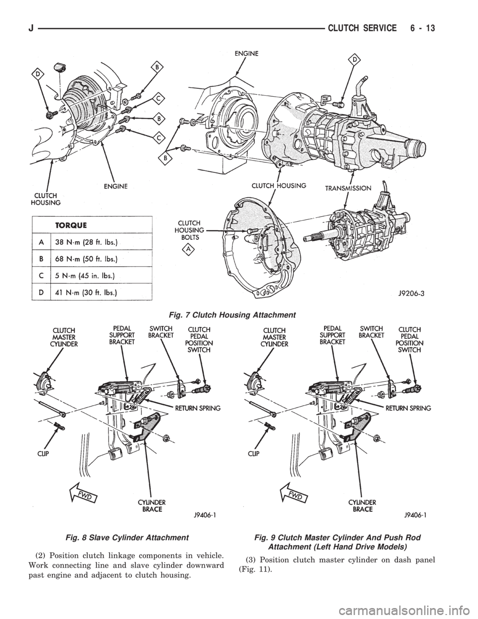
(2) Position clutch linkage components in vehicle.
Work connecting line and slave cylinder downward
past engine and adjacent to clutch housing.(3) Position clutch master cylinder on dash panel
(Fig. 11).
Fig. 7 Clutch Housing Attachment
Fig. 8 Slave Cylinder AttachmentFig. 9 Clutch Master Cylinder And Push Rod
Attachment (Left Hand Drive Models)
JCLUTCH SERVICE 6 - 13
Page 340 of 1784
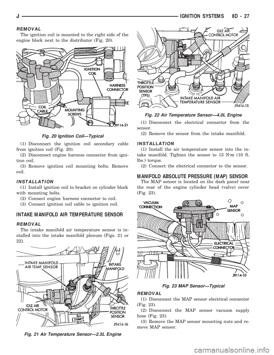
REMOVAL
The ignition coil is mounted to the right side of the
engine block next to the distributor (Fig. 20).
(1) Disconnect the ignition coil secondary cable
from ignition coil (Fig. 20).
(2) Disconnect engine harness connector from igni-
tion coil.
(3) Remove ignition coil mounting bolts. Remove
coil.
INSTALLATION
(1) Install ignition coil to bracket on cylinder block
with mounting bolts.
(2) Connect engine harness connector to coil.
(3) Connect ignition coil cable to ignition coil.
INTAKE MANIFOLD AIR TEMPERATURE SENSOR
REMOVAL
The intake manifold air temperature sensor is in-
stalled into the intake manifold plenum (Figs. 21 or
22).(1) Disconnect the electrical connector from the
sensor.
(2) Remove the sensor from the intake manifold.
INSTALLATION
(1) Install the air temperature sensor into the in-
take manifold. Tighten the sensor to 13 Nzm (10 ft.
lbs.) torque.
(2) Connect the electrical connector to the sensor.
MANIFOLD ABSOLUTE PRESSURE (MAP) SENSOR
The MAP sensor is located on the dash panel near
the rear of the engine cylinder head (valve) cover
(Fig. 23).
REMOVAL
(1) Disconnect the MAP sensor electrical connector
(Fig. 23).
(2) Disconnect the MAP sensor vacuum supply
hose (Fig. 23).
(3) Remove the MAP sensor mounting nuts and re-
move MAP sensor.
Fig. 20 Ignition CoilÐTypical
Fig. 21 Air Temperature SensorÐ2.5L Engine
Fig. 22 Air Temperature SensorÐ4.0L Engine
Fig. 23 MAP SensorÐTypical
JIGNITION SYSTEMS 8D - 27
Page 341 of 1784
INSTALLATION
(1) Install MAP sensor to dash panel and secure
with mounting nuts.
(2) Install the MAP sensor vacuum supply hose.
(3) Connect the MAP sensor electrical connector.
OXYGEN (O2S) SENSOR
For diagnostics and removal/installation proce-
dures, refer to Group 14, Fuel Systems, in this man-
ual.
POWERTRAIN CONTROL MODULE (PCM)
The PCM was formerly referred to as the SBEC or
engine controller.
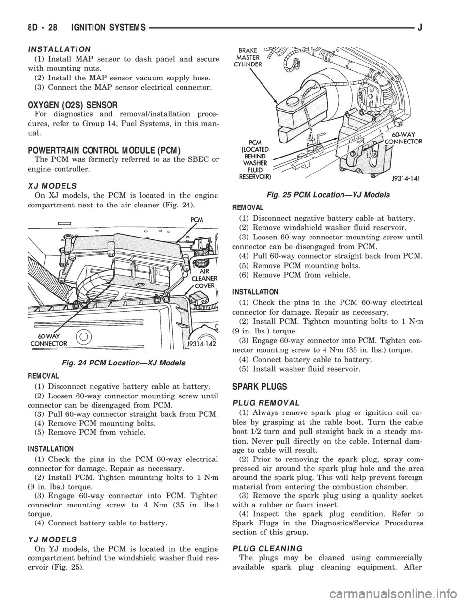
XJ MODELS
On XJ models, the PCM is located in the engine
compartment next to the air cleaner (Fig. 24).
REMOVAL
(1) Disconnect negative battery cable at battery.
(2) Loosen 60-way connector mounting screw until
connector can be disengaged from PCM.
(3) Pull 60-way connector straight back from PCM.
(4) Remove PCM mounting bolts.
(5) Remove PCM from vehicle.
INSTALLATION
(1) Check the pins in the PCM 60-way electrical
connector for damage. Repair as necessary.
(2) Install PCM. Tighten mounting bolts to 1 Nzm
(9 in. lbs.) torque.
(3) Engage 60-way connector into PCM. Tighten
connector mounting screw to 4 Nzm (35 in. lbs.)
torque.
(4) Connect battery cable to battery.
YJ MODELS
On YJ models, the PCM is located in the engine
compartment behind the windshield washer fluid res-
ervoir (Fig. 25).REMOVAL
(1) Disconnect negative battery cable at battery.
(2) Remove windshield washer fluid reservoir.
(3) Loosen 60-way connector mounting screw until
connector can be disengaged from PCM.
(4) Pull 60-way connector straight back from PCM.
(5) Remove PCM mounting bolts.
(6) Remove PCM from vehicle.
INSTALLATION
(1) Check the pins in the PCM 60-way electrical
connector for damage. Repair as necessary.
(2) Install PCM. Tighten mounting bolts to 1 Nzm
(9 in. lbs.) torque.
(3) Engage 60-way connector into PCM. Tighten con-
nector mounting screw to 4 Nzm (35 in. lbs.) torque.
(4) Connect battery cable to battery.
(5) Install washer fluid reservoir.
SPARK PLUGS
PLUG REMOVAL
(1) Always remove spark plug or ignition coil ca-
bles by grasping at the cable boot. Turn the cable
boot 1/2 turn and pull straight back in a steady mo-
tion. Never pull directly on the cable. Internal dam-
age to cable will result.
(2) Prior to removing the spark plug, spray com-
pressed air around the spark plug hole and the area
around the spark plug. This will help prevent foreign
material from entering the combustion chamber.
(3) Remove the spark plug using a quality socket
with a rubber or foam insert.
(4) Inspect the spark plug condition. Refer to
Spark Plugs in the Diagnostics/Service Procedures
section of this group.
PLUG CLEANING
The plugs may be cleaned using commercially
available spark plug cleaning equipment. After
Fig. 24 PCM LocationÐXJ Models
Fig. 25 PCM LocationÐYJ Models
8D - 28 IGNITION SYSTEMSJ
Page 379 of 1784
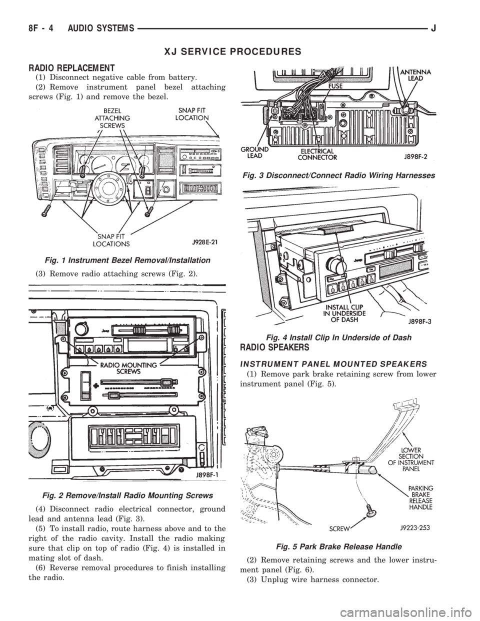
XJ SERVICE PROCEDURES
RADIO REPLACEMENT
(1) Disconnect negative cable from battery.
(2) Remove instrument panel bezel attaching
screws (Fig. 1) and remove the bezel.
(3) Remove radio attaching screws (Fig. 2).
(4) Disconnect radio electrical connector, ground
lead and antenna lead (Fig. 3).
(5) To install radio, route harness above and to the
right of the radio cavity. Install the radio making
sure that clip on top of radio (Fig. 4) is installed in
mating slot of dash.
(6) Reverse removal procedures to finish installing
the radio.
RADIO SPEAKERS
INSTRUMENT PANEL MOUNTED SPEAKERS
(1) Remove park brake retaining screw from lower
instrument panel (Fig. 5).
(2) Remove retaining screws and the lower instru-
ment panel (Fig. 6).
(3) Unplug wire harness connector.
Fig. 3 Disconnect/Connect Radio Wiring Harnesses
Fig. 4 Install Clip In Underside of Dash
Fig. 5 Park Brake Release Handle
Fig. 1 Instrument Bezel Removal/Installation
Fig. 2 Remove/Install Radio Mounting Screws
8F - 4 AUDIO SYSTEMSJ
Page 381 of 1784
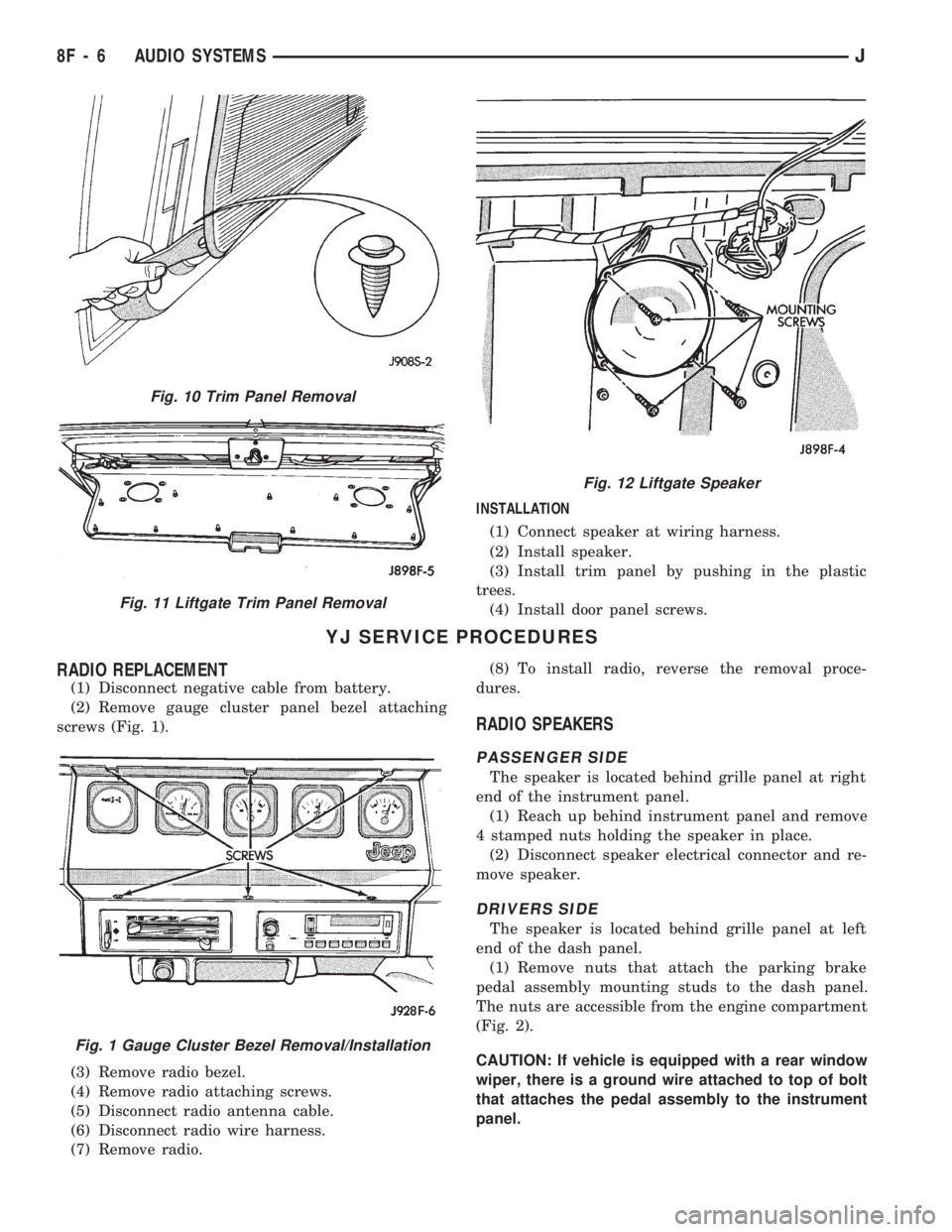
INSTALLATION
(1) Connect speaker at wiring harness.
(2) Install speaker.
(3) Install trim panel by pushing in the plastic
trees.
(4) Install door panel screws.
YJ SERVICE PROCEDURES
RADIO REPLACEMENT
(1) Disconnect negative cable from battery.
(2) Remove gauge cluster panel bezel attaching
screws (Fig. 1).
(3) Remove radio bezel.
(4) Remove radio attaching screws.
(5) Disconnect radio antenna cable.
(6) Disconnect radio wire harness.
(7) Remove radio.(8) To install radio, reverse the removal proce-
dures.
RADIO SPEAKERS
PASSENGER SIDE
The speaker is located behind grille panel at right
end of the instrument panel.
(1) Reach up behind instrument panel and remove
4 stamped nuts holding the speaker in place.
(2) Disconnect speaker electrical connector and re-
move speaker.
DRIVERS SIDE
The speaker is located behind grille panel at left
end of the dash panel.
(1) Remove nuts that attach the parking brake
pedal assembly mounting studs to the dash panel.
The nuts are accessible from the engine compartment
(Fig. 2).
CAUTION: If vehicle is equipped with a rear window
wiper, there is a ground wire attached to top of bolt
that attaches the pedal assembly to the instrument
panel.
Fig. 10 Trim Panel Removal
Fig. 11 Liftgate Trim Panel Removal
Fig. 12 Liftgate Speaker
Fig. 1 Gauge Cluster Bezel Removal/Installation
8F - 6 AUDIO SYSTEMSJ