dash JEEP CHEROKEE 1994 Service Repair Manual
[x] Cancel search | Manufacturer: JEEP, Model Year: 1994, Model line: CHEROKEE, Model: JEEP CHEROKEE 1994Pages: 1784, PDF Size: 77.09 MB
Page 34 of 1784
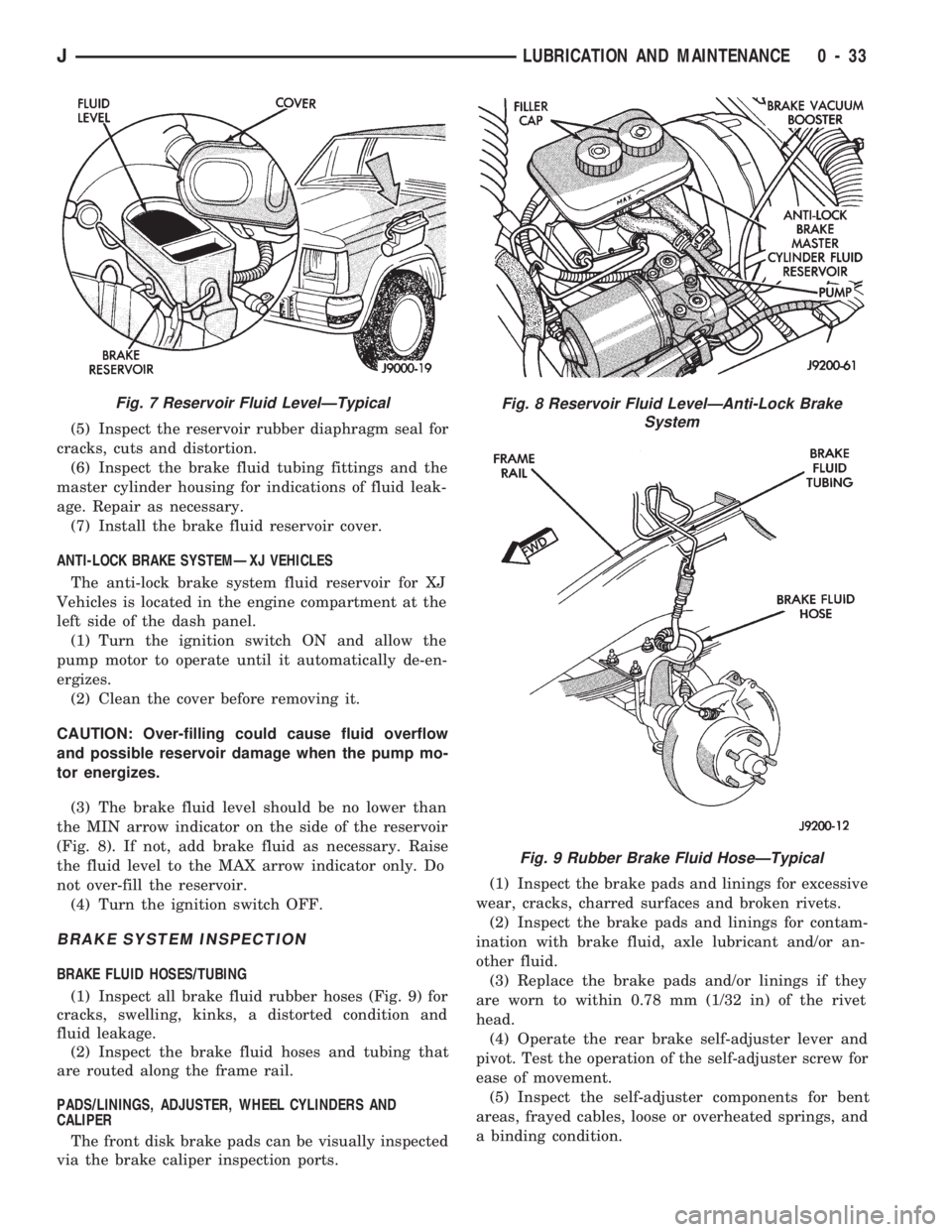
(5) Inspect the reservoir rubber diaphragm seal for
cracks, cuts and distortion.
(6) Inspect the brake fluid tubing fittings and the
master cylinder housing for indications of fluid leak-
age. Repair as necessary.
(7) Install the brake fluid reservoir cover.
ANTI-LOCK BRAKE SYSTEMÐXJ VEHICLES
The anti-lock brake system fluid reservoir for XJ
Vehicles is located in the engine compartment at the
left side of the dash panel.
(1) Turn the ignition switch ON and allow the
pump motor to operate until it automatically de-en-
ergizes.
(2) Clean the cover before removing it.
CAUTION: Over-filling could cause fluid overflow
and possible reservoir damage when the pump mo-
tor energizes.
(3) The brake fluid level should be no lower than
the MIN arrow indicator on the side of the reservoir
(Fig. 8). If not, add brake fluid as necessary. Raise
the fluid level to the MAX arrow indicator only. Do
not over-fill the reservoir.
(4) Turn the ignition switch OFF.
BRAKE SYSTEM INSPECTION
BRAKE FLUID HOSES/TUBING
(1) Inspect all brake fluid rubber hoses (Fig. 9) for
cracks, swelling, kinks, a distorted condition and
fluid leakage.
(2) Inspect the brake fluid hoses and tubing that
are routed along the frame rail.
PADS/LININGS, ADJUSTER, WHEEL CYLINDERS AND
CALIPER
The front disk brake pads can be visually inspected
via the brake caliper inspection ports.(1) Inspect the brake pads and linings for excessive
wear, cracks, charred surfaces and broken rivets.
(2) Inspect the brake pads and linings for contam-
ination with brake fluid, axle lubricant and/or an-
other fluid.
(3) Replace the brake pads and/or linings if they
are worn to within 0.78 mm (1/32 in) of the rivet
head.
(4) Operate the rear brake self-adjuster lever and
pivot. Test the operation of the self-adjuster screw for
ease of movement.
(5) Inspect the self-adjuster components for bent
areas, frayed cables, loose or overheated springs, and
a binding condition.
Fig. 7 Reservoir Fluid LevelÐTypicalFig. 8 Reservoir Fluid LevelÐAnti-Lock Brake
System
Fig. 9 Rubber Brake Fluid HoseÐTypical
JLUBRICATION AND MAINTENANCE 0 - 33
Page 101 of 1784
ACCELERATOR PEDAL AND THROTTLE CABLE
GENERAL INFORMATION
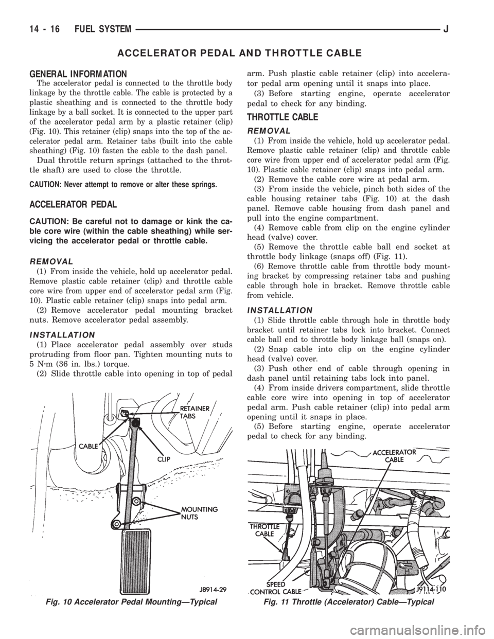
The accelerator pedal is connected to the throttle body
linkage by the throttle cable. The cable is protected by a
plastic sheathing and is connected to the throttle body
linkage by a ball socket. It is connected to the upper part
of the accelerator pedal arm by a plastic retainer (clip)
(Fig. 10). This retainer (clip) snaps into the top of the ac-
celerator pedal arm. Retainer tabs (built into the cable
sheathing) (Fig. 10) fasten the cable to the dash panel.
Dual throttle return springs (attached to the throt-
tle shaft) are used to close the throttle.
CAUTION: Never attempt to remove or alter these springs.
ACCELERATOR PEDAL
CAUTION: Be careful not to damage or kink the ca-
ble core wire (within the cable sheathing) while ser-
vicing the accelerator pedal or throttle cable.
REMOVAL
(1) From inside the vehicle, hold up accelerator pedal.
Remove plastic cable retainer (clip) and throttle cable
core wire from upper end of accelerator pedal arm (Fig.
10). Plastic cable retainer (clip) snaps into pedal arm.
(2) Remove accelerator pedal mounting bracket
nuts. Remove accelerator pedal assembly.
INSTALLATION
(1) Place accelerator pedal assembly over studs
protruding from floor pan. Tighten mounting nuts to
5Nzm (36 in. lbs.) torque.
(2) Slide throttle cable into opening in top of pedalarm. Push plastic cable retainer (clip) into accelera-
tor pedal arm opening until it snaps into place.
(3) Before starting engine, operate accelerator
pedal to check for any binding.
THROTTLE CABLE
REMOVAL
(1) From inside the vehicle, hold up accelerator pedal.
Remove plastic cable retainer (clip) and throttle cable
core wire from upper end of accelerator pedal arm (Fig.
10). Plastic cable retainer (clip) snaps into pedal arm.
(2) Remove the cable core wire at pedal arm.
(3) From inside the vehicle, pinch both sides of the
cable housing retainer tabs (Fig. 10) at the dash
panel. Remove cable housing from dash panel and
pull into the engine compartment.
(4) Remove cable from clip on the engine cylinder
head (valve) cover.
(5) Remove the throttle cable ball end socket at
throttle body linkage (snaps off) (Fig. 11).
(6) Remove throttle cable from throttle body mount-
ing bracket by compressing retainer tabs and pushing
cable through hole in bracket. Remove throttle cable
from vehicle.
INSTALLATION
(1) Slide throttle cable through hole in throttle body
bracket until retainer tabs lock into bracket. Connect
cable ball end to throttle body linkage ball (snaps on).
(2) Snap cable into clip on the engine cylinder
head (valve) cover.
(3) Push other end of cable through opening in
dash panel until retaining tabs lock into panel.
(4) From inside drivers compartment, slide throttle
cable core wire into opening in top of accelerator
pedal arm. Push cable retainer (clip) into pedal arm
opening until it snaps in place.
(5) Before starting engine, operate accelerator
pedal to check for any binding.
Fig. 10 Accelerator Pedal MountingÐTypicalFig. 11 Throttle (Accelerator) CableÐTypical
14 - 16 FUEL SYSTEMJ
Page 106 of 1784
Refer to Group 8D, Ignition System for more crank-
shaft position sensor information.
The engine will not operate if the PCM does not re-
ceive a crankshaft position sensor input.
ENGINE COOLANT TEMPERATURE SENSORÐPCM
INPUT
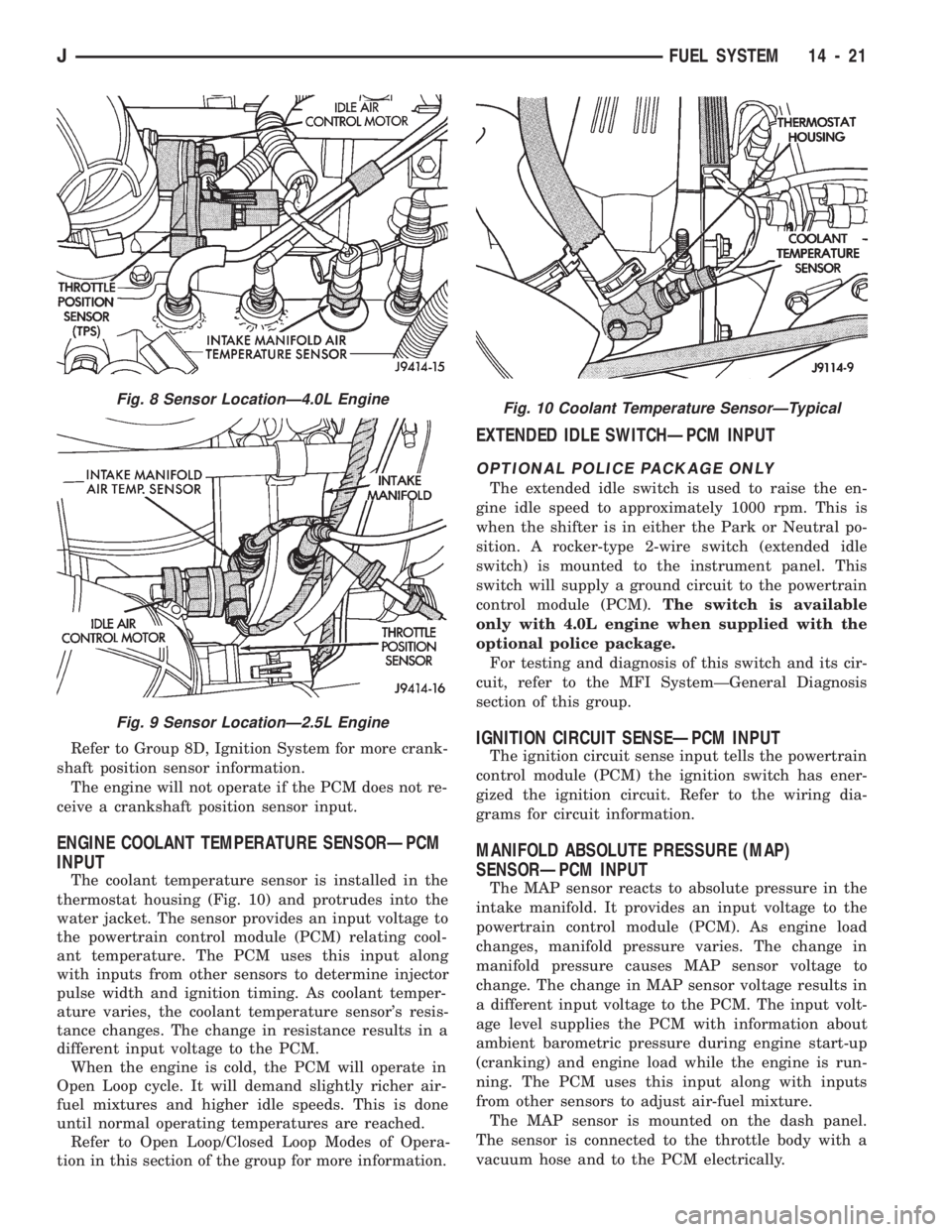
The coolant temperature sensor is installed in the
thermostat housing (Fig. 10) and protrudes into the
water jacket. The sensor provides an input voltage to
the powertrain control module (PCM) relating cool-
ant temperature. The PCM uses this input along
with inputs from other sensors to determine injector
pulse width and ignition timing. As coolant temper-
ature varies, the coolant temperature sensor's resis-
tance changes. The change in resistance results in a
different input voltage to the PCM.
When the engine is cold, the PCM will operate in
Open Loop cycle. It will demand slightly richer air-
fuel mixtures and higher idle speeds. This is done
until normal operating temperatures are reached.
Refer to Open Loop/Closed Loop Modes of Opera-
tion in this section of the group for more information.
EXTENDED IDLE SWITCHÐPCM INPUT
OPTIONAL POLICE PACKAGE ONLY
The extended idle switch is used to raise the en-
gine idle speed to approximately 1000 rpm. This is
when the shifter is in either the Park or Neutral po-
sition. A rocker-type 2-wire switch (extended idle
switch) is mounted to the instrument panel. This
switch will supply a ground circuit to the powertrain
control module (PCM).The switch is available
only with 4.0L engine when supplied with the
optional police package.
For testing and diagnosis of this switch and its cir-
cuit, refer to the MFI SystemÐGeneral Diagnosis
section of this group.
IGNITION CIRCUIT SENSEÐPCM INPUT
The ignition circuit sense input tells the powertrain
control module (PCM) the ignition switch has ener-
gized the ignition circuit. Refer to the wiring dia-
grams for circuit information.
MANIFOLD ABSOLUTE PRESSURE (MAP)
SENSORÐPCM INPUT
The MAP sensor reacts to absolute pressure in the
intake manifold. It provides an input voltage to the
powertrain control module (PCM). As engine load
changes, manifold pressure varies. The change in
manifold pressure causes MAP sensor voltage to
change. The change in MAP sensor voltage results in
a different input voltage to the PCM. The input volt-
age level supplies the PCM with information about
ambient barometric pressure during engine start-up
(cranking) and engine load while the engine is run-
ning. The PCM uses this input along with inputs
from other sensors to adjust air-fuel mixture.
The MAP sensor is mounted on the dash panel.
The sensor is connected to the throttle body with a
vacuum hose and to the PCM electrically.
Fig. 8 Sensor LocationÐ4.0L Engine
Fig. 9 Sensor LocationÐ2.5L Engine
Fig. 10 Coolant Temperature SensorÐTypical
JFUEL SYSTEM 14 - 21
Page 120 of 1784
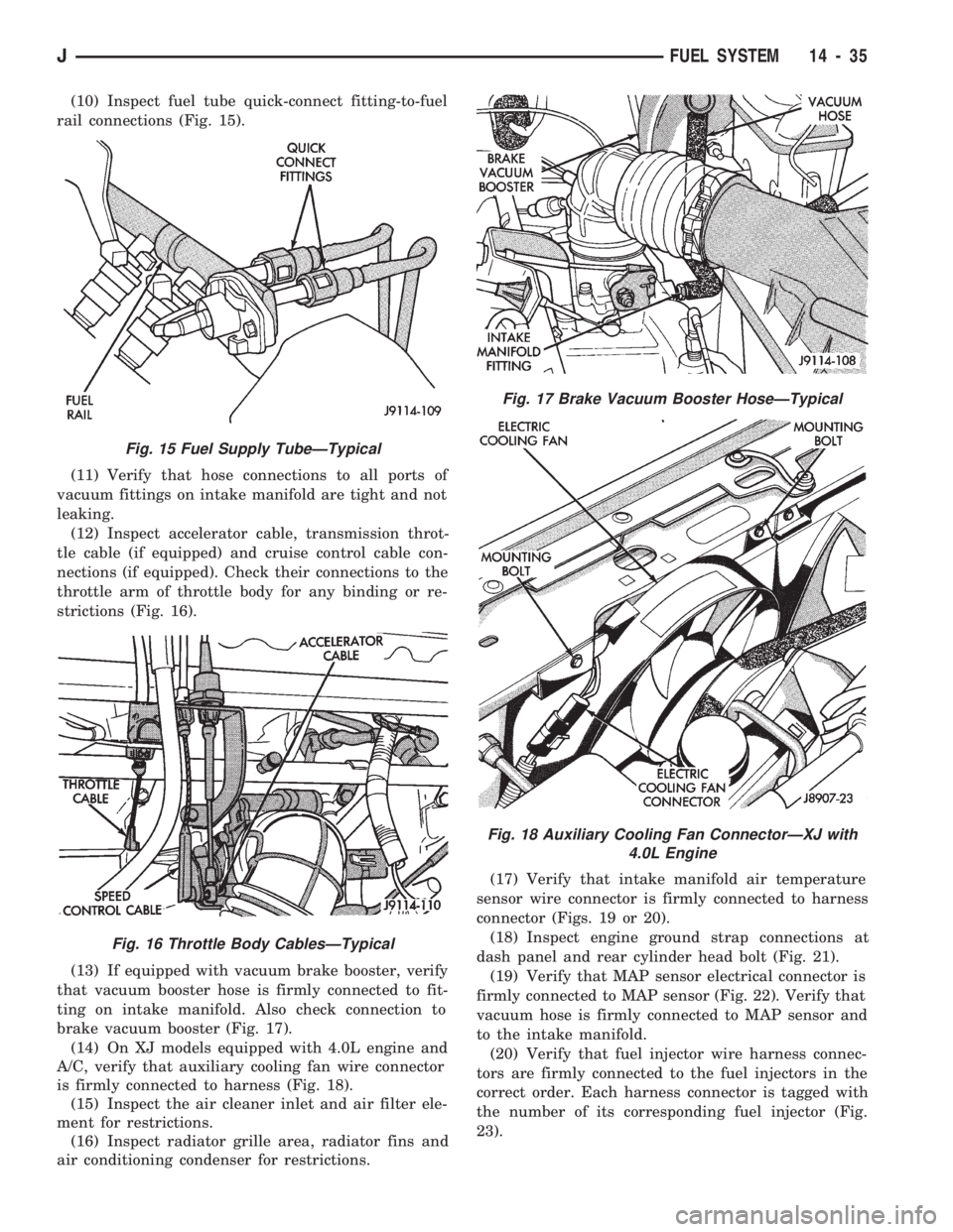
(10) Inspect fuel tube quick-connect fitting-to-fuel
rail connections (Fig. 15).
(11) Verify that hose connections to all ports of
vacuum fittings on intake manifold are tight and not
leaking.
(12) Inspect accelerator cable, transmission throt-
tle cable (if equipped) and cruise control cable con-
nections (if equipped). Check their connections to the
throttle arm of throttle body for any binding or re-
strictions (Fig. 16).
(13) If equipped with vacuum brake booster, verify
that vacuum booster hose is firmly connected to fit-
ting on intake manifold. Also check connection to
brake vacuum booster (Fig. 17).
(14) On XJ models equipped with 4.0L engine and
A/C, verify that auxiliary cooling fan wire connector
is firmly connected to harness (Fig. 18).
(15) Inspect the air cleaner inlet and air filter ele-
ment for restrictions.
(16) Inspect radiator grille area, radiator fins and
air conditioning condenser for restrictions.(17) Verify that intake manifold air temperature
sensor wire connector is firmly connected to harness
connector (Figs. 19 or 20).
(18) Inspect engine ground strap connections at
dash panel and rear cylinder head bolt (Fig. 21).
(19) Verify that MAP sensor electrical connector is
firmly connected to MAP sensor (Fig. 22). Verify that
vacuum hose is firmly connected to MAP sensor and
to the intake manifold.
(20) Verify that fuel injector wire harness connec-
tors are firmly connected to the fuel injectors in the
correct order. Each harness connector is tagged with
the number of its corresponding fuel injector (Fig.
23).
Fig. 15 Fuel Supply TubeÐTypical
Fig. 16 Throttle Body CablesÐTypical
Fig. 17 Brake Vacuum Booster HoseÐTypical
Fig. 18 Auxiliary Cooling Fan ConnectorÐXJ with
4.0L Engine
JFUEL SYSTEM 14 - 35
Page 142 of 1784
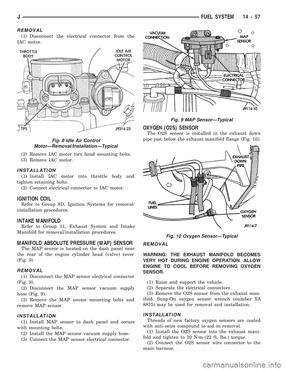
REMOVAL
(1) Disconnect the electrical connector from the
IAC motor.
(2) Remove IAC motor torx head mounting bolts.
(3) Remove IAC motor.
INSTALLATION
(1) Install IAC motor into throttle body and
tighten retaining bolts.
(2) Connect electrical connector to IAC motor.
IGNITION COIL
Refer to Group 8D, Ignition Systems for removal/
installation procedures.
INTAKE MANIFOLD
Refer to Group 11, Exhaust System and Intake
Manifold for removal/installation procedures.
MANIFOLD ABSOLUTE PRESSURE (MAP) SENSOR
The MAP sensor is located on the dash panel near
the rear of the engine cylinder head (valve) cover
(Fig. 9).
REMOVAL
(1) Disconnect the MAP sensor electrical connector
(Fig. 9).
(2) Disconnect the MAP sensor vacuum supply
hose (Fig. 9).
(3) Remove the MAP sensor mounting bolts and
remove MAP sensor.
INSTALLATION
(1) Install MAP sensor to dash panel and secure
with mounting bolts.
(2) Install the MAP sensor vacuum supply hose.
(3) Connect the MAP sensor electrical connector.
OXYGEN (O2S) SENSOR
The O2S sensor is installed in the exhaust down
pipe just below the exhaust manifold flange (Fig. 10).
REMOVAL
WARNING: THE EXHAUST MANIFOLD BECOMES
VERY HOT DURING ENGINE OPERATION. ALLOW
ENGINE TO COOL BEFORE REMOVING OXYGEN
SENSOR.
(1) Raise and support the vehicle.
(2) Separate the electrical connectors.
(3) Remove the O2S sensor from the exhaust man-
ifold. Snap-On oxygen sensor wrench (number YA
8875) may be used for removal and installation.
INSTALLATION
Threads of new factory oxygen sensors are coated
with anti-seize compound to aid in removal.
(1) Install the O2S sensor into the exhaust mani-
fold and tighten to 30 Nzm (22 ft. lbs.) torque.
(2) Connect the O2S sensor wire connector to the
main harness.
Fig. 8 Idle Air Control
MotorÐRemoval/InstallationÐTypical
Fig. 9 MAP SensorÐTypical
Fig. 10 Oxygen SensorÐTypical
JFUEL SYSTEM 14 - 57
Page 169 of 1784
POWER BRAKE BOOSTER
INDEX
page page
Power Brake Booster Installation............. 23
Power Brake Booster Operation............. 22Power Brake Booster Removal.............. 22
Service Information....................... 22
SERVICE INFORMATION
The power brake booster is not a serviceable com-
ponent. If a booster malfunction occurs, the booster
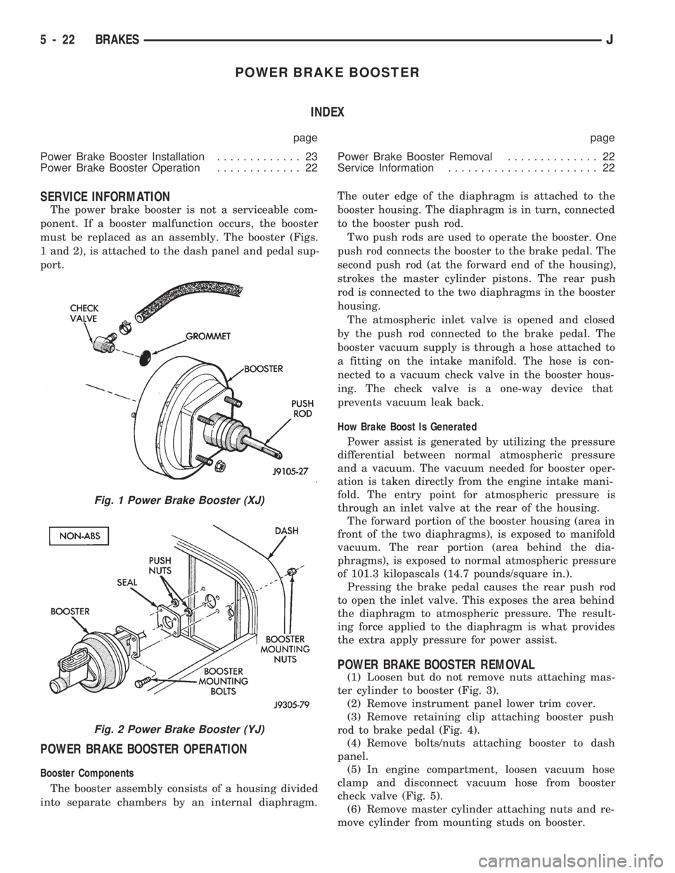
must be replaced as an assembly. The booster (Figs.
1 and 2), is attached to the dash panel and pedal sup-
port.
POWER BRAKE BOOSTER OPERATION
Booster Components
The booster assembly consists of a housing divided
into separate chambers by an internal diaphragm.The outer edge of the diaphragm is attached to the
booster housing. The diaphragm is in turn, connected
to the booster push rod.
Two push rods are used to operate the booster. One
push rod connects the booster to the brake pedal. The
second push rod (at the forward end of the housing),
strokes the master cylinder pistons. The rear push
rod is connected to the two diaphragms in the booster
housing.
The atmospheric inlet valve is opened and closed
by the push rod connected to the brake pedal. The
booster vacuum supply is through a hose attached to
a fitting on the intake manifold. The hose is con-
nected to a vacuum check valve in the booster hous-
ing. The check valve is a one-way device that
prevents vacuum leak back.
How Brake Boost Is Generated
Power assist is generated by utilizing the pressure
differential between normal atmospheric pressure
and a vacuum. The vacuum needed for booster oper-
ation is taken directly from the engine intake mani-
fold. The entry point for atmospheric pressure is
through an inlet valve at the rear of the housing.
The forward portion of the booster housing (area in
front of the two diaphragms), is exposed to manifold
vacuum. The rear portion (area behind the dia-
phragms), is exposed to normal atmospheric pressure
of 101.3 kilopascals (14.7 pounds/square in.).
Pressing the brake pedal causes the rear push rod
to open the inlet valve. This exposes the area behind
the diaphragm to atmospheric pressure. The result-
ing force applied to the diaphragm is what provides
the extra apply pressure for power assist.
POWER BRAKE BOOSTER REMOVAL
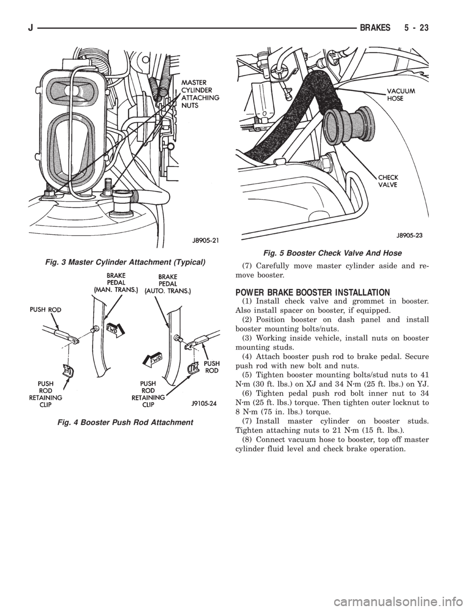
(1) Loosen but do not remove nuts attaching mas-
ter cylinder to booster (Fig. 3).
(2) Remove instrument panel lower trim cover.
(3) Remove retaining clip attaching booster push
rod to brake pedal (Fig. 4).
(4) Remove bolts/nuts attaching booster to dash
panel.
(5) In engine compartment, loosen vacuum hose
clamp and disconnect vacuum hose from booster
check valve (Fig. 5).
(6) Remove master cylinder attaching nuts and re-
move cylinder from mounting studs on booster.
Fig. 1 Power Brake Booster (XJ)
Fig. 2 Power Brake Booster (YJ)
5 - 22 BRAKESJ
Page 170 of 1784
(7) Carefully move master cylinder aside and re-
move booster.
POWER BRAKE BOOSTER INSTALLATION
(1) Install check valve and grommet in booster.
Also install spacer on booster, if equipped.
(2) Position booster on dash panel and install
booster mounting bolts/nuts.
(3) Working inside vehicle, install nuts on booster
mounting studs.
(4) Attach booster push rod to brake pedal. Secure
push rod with new bolt and nuts.
(5) Tighten booster mounting bolts/stud nuts to 41
Nzm (30 ft. lbs.) on XJ and 34 Nzm (25 ft. lbs.) on YJ.
(6) Tighten pedal push rod bolt inner nut to 34
Nzm (25 ft. lbs.) torque. Then tighten outer locknut to
8Nzm (75 in. lbs.) torque.
(7) Install master cylinder on booster studs.
Tighten attaching nuts to 21 Nzm (15 ft. lbs.).
(8) Connect vacuum hose to booster, top off master
cylinder fluid level and check brake operation.
Fig. 3 Master Cylinder Attachment (Typical)
Fig. 4 Booster Push Rod Attachment
Fig. 5 Booster Check Valve And Hose
JBRAKES 5 - 23
Page 188 of 1784
4). The engine intake manifold serves as the vacuum
source for booster operation.
The booster is mounted on the engine compartment
side of the dash panel. The master cylinder is
mounted on attaching studs at the front of the
booster. The master cylinder central valves are di-
rectly actuated by the booster push rod.
The pedal travel sensor is mounted in the forward
face of the booster shell. The sensor plunger is actu-
ated by the booster diaphragm plate.
PEDAL TRAVEL SENSOR
The pedal travel sensor signals brake pedal posi-
tion to the antilock ECU. The sensor signal is based
on changes in electrical resistance. The resistance
changes occur in steps that are generated by changes
in brake pedal position. A resistance signal gener-
ated by changing brake pedal position, will cause the
ECU to run the antilock pump when necessary.
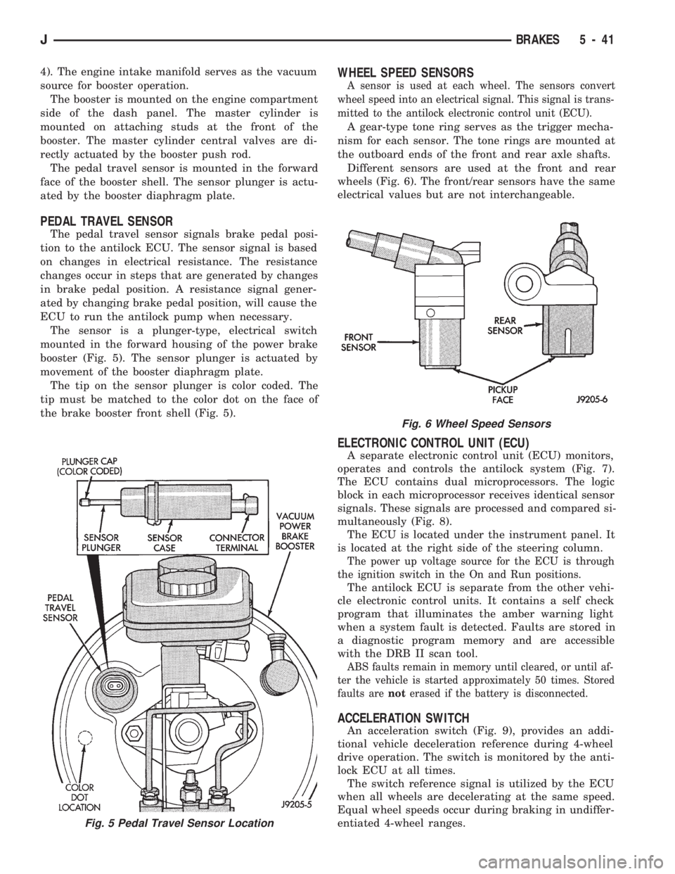
The sensor is a plunger-type, electrical switch
mounted in the forward housing of the power brake
booster (Fig. 5). The sensor plunger is actuated by
movement of the booster diaphragm plate.
The tip on the sensor plunger is color coded. The
tip must be matched to the color dot on the face of
the brake booster front shell (Fig. 5).
WHEEL SPEED SENSORS
A sensor is used at each wheel. The sensors convert
wheel speed into an electrical signal. This signal is trans-
mitted to the antilock electronic control unit (ECU).
A gear-type tone ring serves as the trigger mecha-
nism for each sensor. The tone rings are mounted at
the outboard ends of the front and rear axle shafts.
Different sensors are used at the front and rear
wheels (Fig. 6). The front/rear sensors have the same
electrical values but are not interchangeable.
ELECTRONIC CONTROL UNIT (ECU)
A separate electronic control unit (ECU) monitors,
operates and controls the antilock system (Fig. 7).
The ECU contains dual microprocessors. The logic
block in each microprocessor receives identical sensor
signals. These signals are processed and compared si-
multaneously (Fig. 8).
The ECU is located under the instrument panel. It
is located at the right side of the steering column.
The power up voltage source for the ECU is through
the ignition switch in the On and Run positions.
The antilock ECU is separate from the other vehi-
cle electronic control units. It contains a self check
program that illuminates the amber warning light
when a system fault is detected. Faults are stored in
a diagnostic program memory and are accessible
with the DRB II scan tool.
ABS faults remain in memory until cleared, or until af-
ter the vehicle is started approximately 50 times. Stored
faults arenoterased if the battery is disconnected.
ACCELERATION SWITCH
An acceleration switch (Fig. 9), provides an addi-
tional vehicle deceleration reference during 4-wheel
drive operation. The switch is monitored by the anti-
lock ECU at all times.
The switch reference signal is utilized by the ECU
when all wheels are decelerating at the same speed.
Equal wheel speeds occur during braking in undiffer-
entiated 4-wheel ranges.
Fig. 5 Pedal Travel Sensor Location
Fig. 6 Wheel Speed Sensors
JBRAKES 5 - 41
Page 198 of 1784
(9) Fill reservoir and bleed brakes. Refer to proce-
dure in this section.
(10) Install air cleaner and hoses.
PEDAL TRAVEL SENSOR SERVICE
CAUTION: The pedal travel sensor and booster
must form a matched set. The cap on the sensor
plunger and booster shell are color coded for iden-
tification, and to ensure they are used as matched
sets. Be sure the color of the sensor cap and the
color dot on the booster shell are the same before
installation. Refer to the Sensor Replacement infor-
mation before installing a new or original sensor.
PEDAL TRAVEL SENSOR REMOVAL
(1) Disconnect wires at sensor.
(2) Pump brake pedal to exhaust all vacuum from
booster.
(3) Unseat sensor retaining ring.
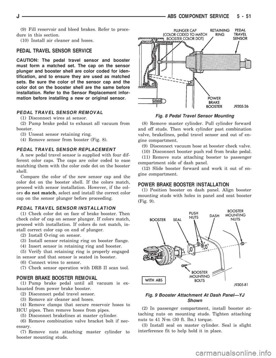
(4) Remove sensor from booster (Fig. 8).
PEDAL TRAVEL SENSOR REPLACEMENT
A new pedal travel sensor is supplied with four dif-
ferent color caps. The caps are color coded to ease
matching them with the color code dot on the booster
shell.
Compare the color of the new sensor cap and the
color dot on the booster shell. If the colors match,
proceed with sensor installation. However, if the col-
orsdo not match, select and install the correct color
cap on the sensor plunger before proceeding.
PEDAL TRAVEL SENSOR INSTALLATION
(1) Check color dot on face of brake booster. Then
check color of cap on sensor plunger. If colors match,
proceed with installation. If colors do not match, in-
stall correct color cap on end of plunger.
(2) Install O-ring on sensor.
(3) Install sensor retaining ring on booster flange.
(4) Insert sensor in retaining ring and booster.
(5) Verify that retaining ring is properly engaged
in sensor and that sensor is seated in booster.
(6) Connect wires to sensor.
(7) Check sensor operation with DRB II scan tool.
POWER BRAKE BOOSTER REMOVAL
(1) Pump brake pedal until all vacuum is ex-
hausted from power brake booster.
(2) Disconnect pedal travel sensor.
(3) Remove air cleaner and hoses.
(4) Remove clamps that secure reservoir hoses to
HCU pipes. Then remove hoses from pipes.
(5) Disconnect brakelines at master cylinder.
(6) Remove combination valve bracket bolt if nec-
essary.
(7) Remove nuts attaching master cylinder to
booster mounting studs.(8) Remove master cylinder. Pull cylinder forward
and off studs. Then work cylinder past combination
valve, brakelines, pedal travel sensor and out of en-
gine compartment.
(9) Disconnect vacuum hose at booster check valve.
(10) Disconnect booster push rod from brake pedal.
(11) Remove nuts attaching booster to passenger
compartment side of dash panel.
(12) Slide booster forward and work it out of en-
gine compartment.
POWER BRAKE BOOSTER INSTALLATION
(1) Position booster on dash panel. Align booster
mounting studs with holes in panel and seat booster
(Fig. 9).
(2) In passenger compartment, install booster at-
taching nuts on mounting studs. Tighten attaching
nuts to 41 Nzm (30 ft. lbs.) torque.
(3) Install seal on master cylinder. Seal is slight
interference fit to help hold it in place.
Fig. 8 Pedal Travel Sensor Mounting
Fig. 9 Booster Attachment At Dash PanelÐYJ
Shown
JABS COMPONENT SERVICE 5 - 51
Page 200 of 1784
ECU REPLACEMENTÐXJ
ECU Removal
(1) Turn ignition key to Off position.
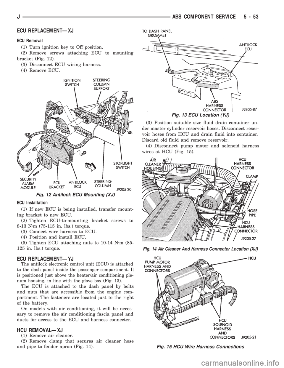
(2) Remove screws attaching ECU to mounting
bracket (Fig. 12).
(3) Disconnect ECU wiring harness.
(4) Remove ECU.
ECU Installation
(1) If new ECU is being installed, transfer mount-
ing bracket to new ECU.
(2) Tighten ECU-to-mounting bracket screws to
8-13 Nzm (75-115 in. lbs.) torque.
(3) Connect wire harness to ECU.
(4) Position and install ECU.
(5) Tighten ECU attaching nuts to 10-14 Nzm (85-
125 in. lbs.) torque.
ECU REPLACEMENTÐYJ
The antilock electronic control unit (ECU) is attached
to the dash panel inside the passenger compartment. It
is positioned just above the heater/air conditioning ple-
num housing, in line with the glove box (Fig. 13).
The ECU is attached to the dash panel by bolts
and nuts that are accessible from the engine com-
partment. The fasteners are located just to the right
of the battery.
On models with air conditioning, it will be neces-
sary to remove the air conditioning fascia panel and
ducts for access to the ECU and harness connecter.
HCU REMOVALÐXJ
(1) Remove air cleaner.
(2) Remove clamp that secures air cleaner hose
and pipe to fender apron (Fig. 14).(3) Position suitable size fluid drain container un-
der master cylinder reservoir hoses. Disconnect reser-
voir hoses from HCU and drain fluid into container.
Discard old fluid and remove reservoir.
(4) Disconnect pump motor and solenoid harness
wires at HCU (Fig. 15).
Fig. 12 Antilock ECU Mounting (XJ)
Fig. 13 ECU Location (YJ)
Fig. 14 Air Cleaner And Harness Connector Location (XJ)
Fig. 15 HCU Wire Harness Connections
JABS COMPONENT SERVICE 5 - 53