length JEEP CHEROKEE 1994 Service User Guide
[x] Cancel search | Manufacturer: JEEP, Model Year: 1994, Model line: CHEROKEE, Model: JEEP CHEROKEE 1994Pages: 1784, PDF Size: 77.09 MB
Page 174 of 1784
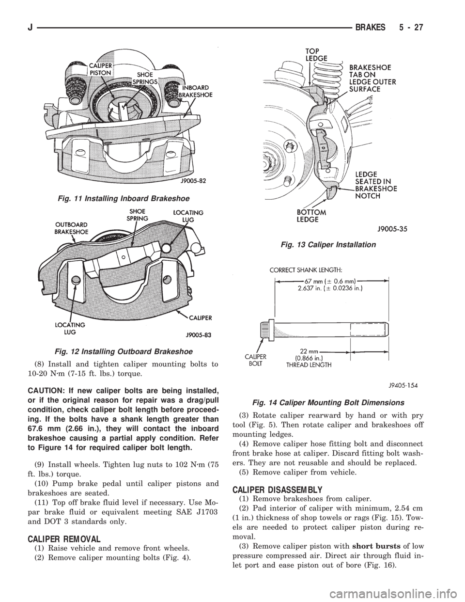
(8) Install and tighten caliper mounting bolts to
10-20 Nzm (7-15 ft. lbs.) torque.
CAUTION: If new caliper bolts are being installed,
or if the original reason for repair was a drag/pull
condition, check caliper bolt length before proceed-
ing. If the bolts have a shank length greater than
67.6 mm (2.66 in.), they will contact the inboard
brakeshoe causing a partial apply condition. Refer
to Figure 14 for required caliper bolt length.
(9) Install wheels. Tighten lug nuts to 102 Nzm (75
ft. lbs.) torque.
(10) Pump brake pedal until caliper pistons and
brakeshoes are seated.
(11) Top off brake fluid level if necessary. Use Mo-
par brake fluid or equivalent meeting SAE J1703
and DOT 3 standards only.
CALIPER REMOVAL
(1) Raise vehicle and remove front wheels.
(2) Remove caliper mounting bolts (Fig. 4).(3) Rotate caliper rearward by hand or with pry
tool (Fig. 5). Then rotate caliper and brakeshoes off
mounting ledges.
(4) Remove caliper hose fitting bolt and disconnect
front brake hose at caliper. Discard fitting bolt wash-
ers. They are not reusable and should be replaced.
(5) Remove caliper from vehicle.
CALIPER DISASSEMBLY
(1) Remove brakeshoes from caliper.
(2) Pad interior of caliper with minimum, 2.54 cm
(1 in.) thickness of shop towels or rags (Fig. 15). Tow-
els are needed to protect caliper piston during re-
moval.
(3) Remove caliper piston withshort burstsof low
pressure compressed air. Direct air through fluid in-
let port and ease piston out of bore (Fig. 16).
Fig. 11 Installing Inboard Brakeshoe
Fig. 12 Installing Outboard Brakeshoe
Fig. 13 Caliper Installation
Fig. 14 Caliper Mounting Bolt Dimensions
JBRAKES 5 - 27
Page 176 of 1784
Do not hone the caliper piston bore. Replace the cal-
iper if the bore exhibits any of the aforementioned
conditions.
Inspect the caliper piston. The piston is made from
a phenolic resin (plastic material) and should be
smooth and clean. Replace the piston if cracked,
chipped, or scored. Do not attempt to restore a
scored, or corroded piston surface by sanding or pol-
ishing. The piston must be replaced if damaged.
CAUTION: Never interchange phenolic resin and
steel caliper pistons. The seals, seal grooves, cali-
per bores and piston tolerances are different for
resin and steel pistons. Do not intermix these com-
ponents.
Inspect the caliper mounting bolt bushings and
boots. Replace the boots if cut or torn. Clean and lu-
bricate the bushings with GE 661 or Dow 111 sili-
cone grease if necessary.
Inspect condition of the caliper mounting bolts. Re-
place the bolts if corroded, rusted, or worn. Do not re-
use the bolts if unsure of their condition.
Length of the caliper mounting bolts is also ex-
tremely important.
Use the replacement bolts specified in the parts
catalog at all times. Do not use substitute bolts.
Bolts that are too long will partially apply the in-
board brakeshoe causing drag and pull. Refer to the
caliper and brakeshoe installation procedures for ser-
vice details and bolt dimensions.
CALIPER ASSEMBLY
(1) Coat caliper piston bore, new piston seal and
piston with clean, fresh brake fluid.
(2) Lubricate caliper bushings and interior of bush-
ing boots with GE 661, Dow 111, or Permatex Dielec-
tric silicone grease.
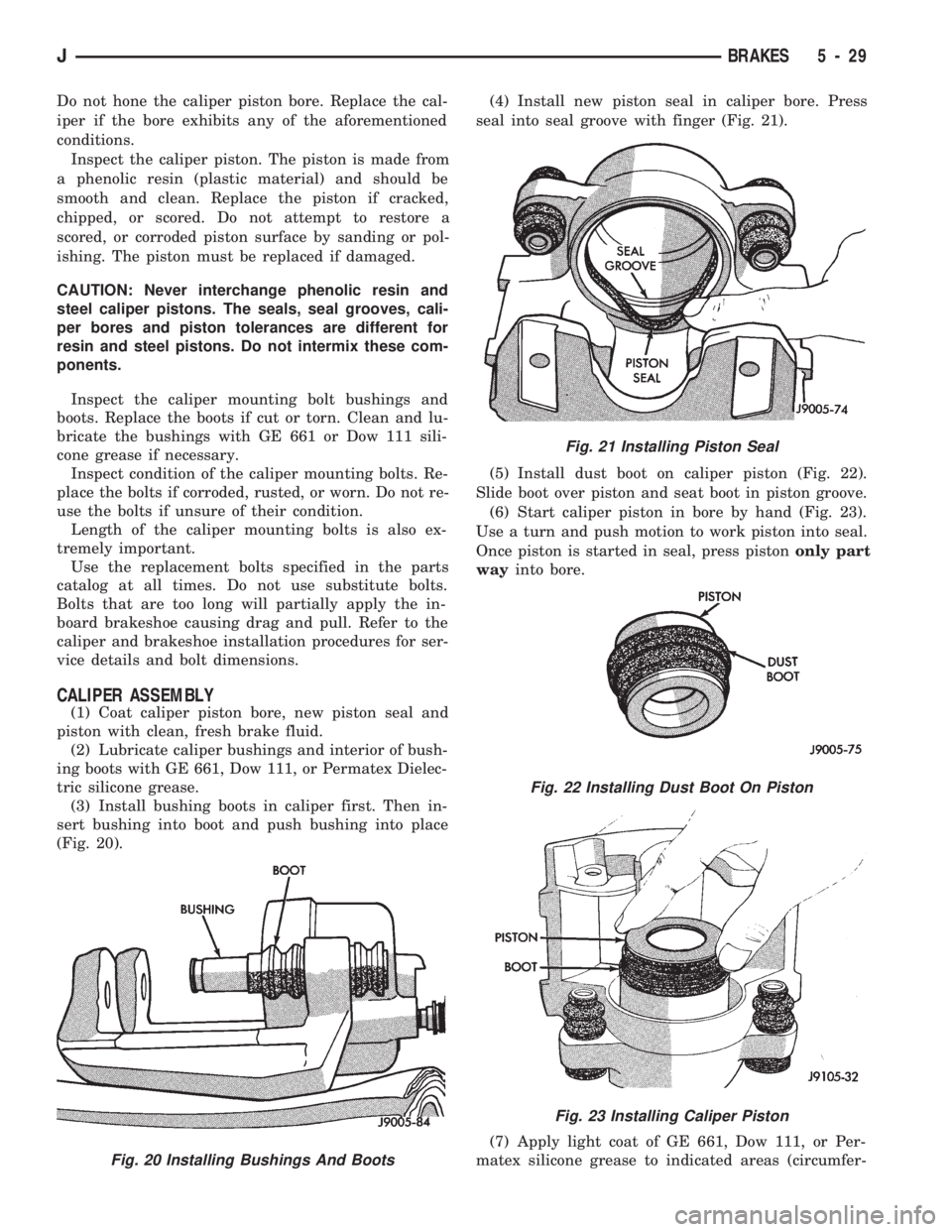
(3) Install bushing boots in caliper first. Then in-
sert bushing into boot and push bushing into place
(Fig. 20).(4) Install new piston seal in caliper bore. Press
seal into seal groove with finger (Fig. 21).
(5) Install dust boot on caliper piston (Fig. 22).
Slide boot over piston and seat boot in piston groove.
(6) Start caliper piston in bore by hand (Fig. 23).
Use a turn and push motion to work piston into seal.
Once piston is started in seal, press pistononly part
wayinto bore.
(7) Apply light coat of GE 661, Dow 111, or Per-
matex silicone grease to indicated areas (circumfer-
Fig. 20 Installing Bushings And Boots
Fig. 21 Installing Piston Seal
Fig. 22 Installing Dust Boot On Piston
Fig. 23 Installing Caliper Piston
JBRAKES 5 - 29
Page 177 of 1784
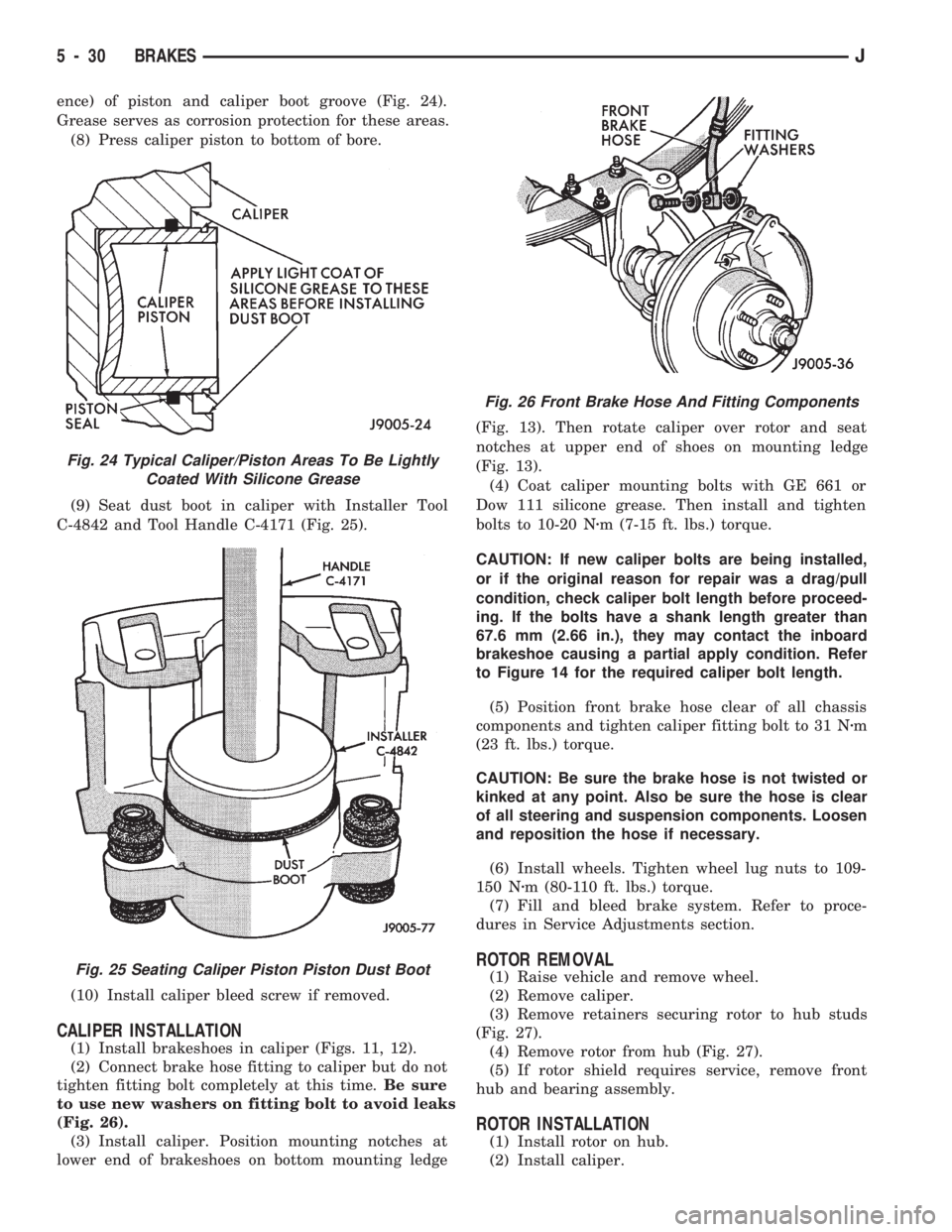
ence) of piston and caliper boot groove (Fig. 24).
Grease serves as corrosion protection for these areas.
(8) Press caliper piston to bottom of bore.
(9) Seat dust boot in caliper with Installer Tool
C-4842 and Tool Handle C-4171 (Fig. 25).
(10) Install caliper bleed screw if removed.
CALIPER INSTALLATION
(1) Install brakeshoes in caliper (Figs. 11, 12).
(2) Connect brake hose fitting to caliper but do not
tighten fitting bolt completely at this time.Be sure
to use new washers on fitting bolt to avoid leaks
(Fig. 26).
(3) Install caliper. Position mounting notches at
lower end of brakeshoes on bottom mounting ledge(Fig. 13). Then rotate caliper over rotor and seat
notches at upper end of shoes on mounting ledge
(Fig. 13).
(4) Coat caliper mounting bolts with GE 661 or
Dow 111 silicone grease. Then install and tighten
bolts to 10-20 Nzm (7-15 ft. lbs.) torque.
CAUTION: If new caliper bolts are being installed,
or if the original reason for repair was a drag/pull
condition, check caliper bolt length before proceed-
ing. If the bolts have a shank length greater than
67.6 mm (2.66 in.), they may contact the inboard
brakeshoe causing a partial apply condition. Refer
to Figure 14 for the required caliper bolt length.
(5) Position front brake hose clear of all chassis
components and tighten caliper fitting bolt to 31 Nzm
(23 ft. lbs.) torque.
CAUTION: Be sure the brake hose is not twisted or
kinked at any point. Also be sure the hose is clear
of all steering and suspension components. Loosen
and reposition the hose if necessary.
(6) Install wheels. Tighten wheel lug nuts to 109-
150 Nzm (80-110 ft. lbs.) torque.
(7) Fill and bleed brake system. Refer to proce-
dures in Service Adjustments section.
ROTOR REMOVAL
(1) Raise vehicle and remove wheel.
(2) Remove caliper.
(3) Remove retainers securing rotor to hub studs
(Fig. 27).
(4) Remove rotor from hub (Fig. 27).
(5) If rotor shield requires service, remove front
hub and bearing assembly.
ROTOR INSTALLATION
(1) Install rotor on hub.
(2) Install caliper.
Fig. 24 Typical Caliper/Piston Areas To Be Lightly
Coated With Silicone Grease
Fig. 25 Seating Caliper Piston Piston Dust Boot
Fig. 26 Front Brake Hose And Fitting Components
5 - 30 BRAKESJ
Page 268 of 1784
CAUTION: When installing the serpentine accessory
drive belt, the belt MUST be routed correctly. If not,
the engine may overheat due to the water pump ro-
tating in the wrong direction. Refer to (Figs. 2, 3, 4
or 5) for correct belt routing.
(6) Install new belt. Refer to the end of this group
for Drive Belt Tension specifications.
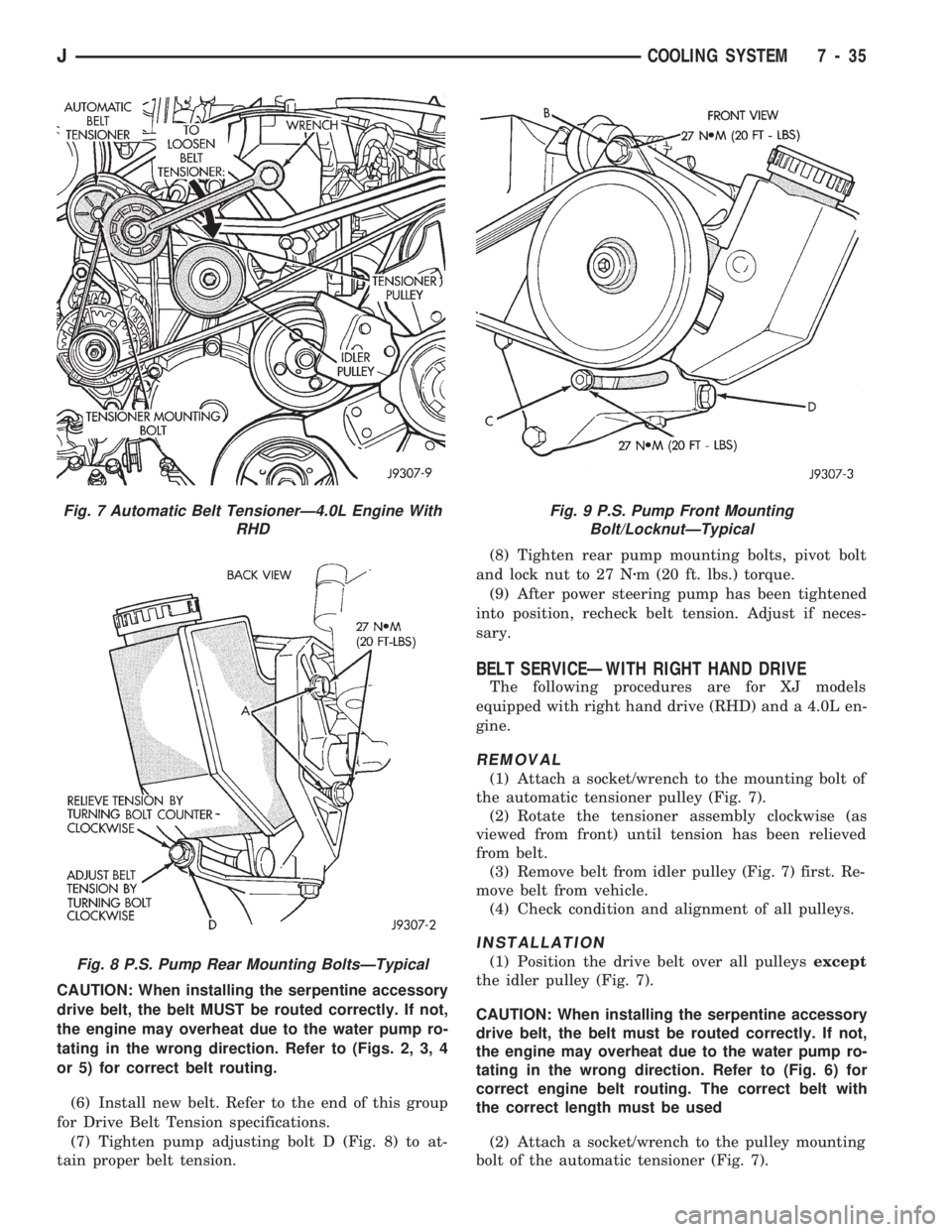
(7) Tighten pump adjusting bolt D (Fig. 8) to at-
tain proper belt tension.(8) Tighten rear pump mounting bolts, pivot bolt
and lock nut to 27 Nzm (20 ft. lbs.) torque.
(9) After power steering pump has been tightened
into position, recheck belt tension. Adjust if neces-
sary.
BELT SERVICEÐWITH RIGHT HAND DRIVE
The following procedures are for XJ models
equipped with right hand drive (RHD) and a 4.0L en-
gine.
REMOVAL
(1) Attach a socket/wrench to the mounting bolt of
the automatic tensioner pulley (Fig. 7).
(2) Rotate the tensioner assembly clockwise (as
viewed from front) until tension has been relieved
from belt.
(3) Remove belt from idler pulley (Fig. 7) first. Re-
move belt from vehicle.
(4) Check condition and alignment of all pulleys.
INSTALLATION
(1) Position the drive belt over all pulleysexcept
the idler pulley (Fig. 7).
CAUTION: When installing the serpentine accessory
drive belt, the belt must be routed correctly. If not,
the engine may overheat due to the water pump ro-
tating in the wrong direction. Refer to (Fig. 6) for
correct engine belt routing. The correct belt with
the correct length must be used
(2) Attach a socket/wrench to the pulley mounting
bolt of the automatic tensioner (Fig. 7).
Fig. 7 Automatic Belt TensionerÐ4.0L Engine With
RHD
Fig. 8 P.S. Pump Rear Mounting BoltsÐTypical
Fig. 9 P.S. Pump Front Mounting
Bolt/LocknutÐTypical
JCOOLING SYSTEM 7 - 35
Page 269 of 1784
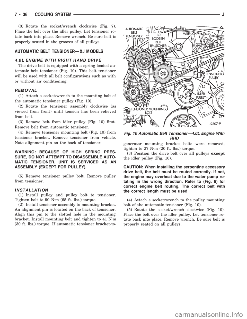
(3) Rotate the socket/wrench clockwise (Fig. 7).
Place the belt over the idler pulley. Let tensioner ro-
tate back into place. Remove wrench. Be sure belt is
properly seated in the grooves of all pulleys.
AUTOMATIC BELT TENSIONERÐXJ MODELS
4.0L ENGINE WITH RIGHT HAND DRIVE
The drive belt is equipped with a spring loaded au-
tomatic belt tensioner (Fig. 10). This belt tensioner
will be used with all belt configurations such as with
or without air conditioning.
REMOVAL
(1) Attach a socket/wrench to the mounting bolt of
the automatic tensioner pulley (Fig. 10).
(2) Rotate the tensioner assembly clockwise (as
viewed from front) until tension has been relieved
from belt.
(3) Remove belt from idler pulley (Fig. 10) first.
Remove belt from automatic tensioner.
(4) Remove tensioner mounting bolt (Fig. 10) from
tensioner bracket. Remove tensioner from vehicle.
Note alignment pin on the back of tensioner.
WARNING: BECAUSE OF HIGH SPRING PRES-
SURE, DO NOT ATTEMPT TO DISASSEMBLE AUTO-
MATIC TENSIONER. UNIT IS SERVICED AS AN
ASSEMBLY (EXCEPT FOR PULLEY).
(5) Remove tensioner pulley bolt. Remove pulley
from tensioner.
INSTALLATION
(1) Install pulley and pulley bolt to tensioner.
Tighten bolt to 90 Nzm (65 ft. lbs.) torque.
(2) Install tensioner assembly to mounting bracket.
An alignment pin is located on the back of tensioner.
Align this pin to the slotted hole in the mounting
bracket. Install mounting bolt and tighten to 41 Nzm
(30 ft. lbs.) torque. If automatic tensioner bracket-to-generator mounting bracket bolts were removed,
tighten to 27 Nzm (20 ft. lbs.) torque.
(3) Position the drive belt over all pulleysexcept
the idler pulley (Fig. 10).
CAUTION: When installing the serpentine accessory
drive belt, the belt must be routed correctly. If not,
the engine may overheat due to the water pump ro-
tating in the wrong direction. Refer to (Fig. 6) for
correct engine belt routing. The correct belt with
the correct length must be used
(4) Attach a socket/wrench to the pulley mounting
bolt of the automatic tensioner (Fig. 10).
(5) Rotate the socket/wrench clockwise (Fig. 10).
Place the belt over the idler pulley. Let tensioner ro-
tate back into place. Remove wrench. Be sure belt is
properly seated on all pulleys.
Fig. 10 Automatic Belt TensionerÐ4.0L Engine With
RHD
7 - 36 COOLING SYSTEMJ
Page 310 of 1784
circles, in not less than 48 seconds. The CAL light
will go off and the compass is now calibrated.
(5) Reset variation number. This step must be
done every time step 2 is performed.
If CAL light does not go off, either there is ex-
cessive magnetism near the compass or the unit
is defective. Repeat the degaussing and calibra-
tion procedures at least one more time.
If the wrong direction is still indicated, the
area selected may be too close to a magnetic
source. Repeat the calibration procedure in an-
other location.
DEGAUSSING PROCEDURE
The tool used to degauss or demagnetize the forward
console attaching screw and roof panel is the Miller
Tool 6029. Equivalent units must be rated as continu-
ous duty for 110/115 volts, 60Hz with a field strength of
over 350 gauss at 1/4 inch beyond the tip of the probe.
In this degaussing procedure the degaussing tool is
used to demagnetize both the roof panel and console
forward mounting screw.
(1) Be sure the ignition switch is in the OFF posi-
tion before you begin the degaussing procedures.
CAUTION: Keep the degaussing tool at least 2 inches
away from the compass area when plugging it in.
(2) Plug the degaussing tool into a standard
110/115 volt AC outlet.
CONSOLE FORWARD MOUNTING SCREW
(3) Slowly approach the head of the forward
mounting screw with the plastic coated tip of the de-
gaussing tool. Contact the head of the screw for
about two seconds.
(4) With the degaussing tool still energized, slowly
back it away from the screw until the tool is at least
2 inches from the screw head then unplug the tool.
ROOF PANEL
(5) Place an 8 1/2 X 11 piece of paper on the center
of the roof at the windshield, oriented lengthwise
from front to rear. The purpose of the paper is pro-
tect the roof panel from scratches and define the area
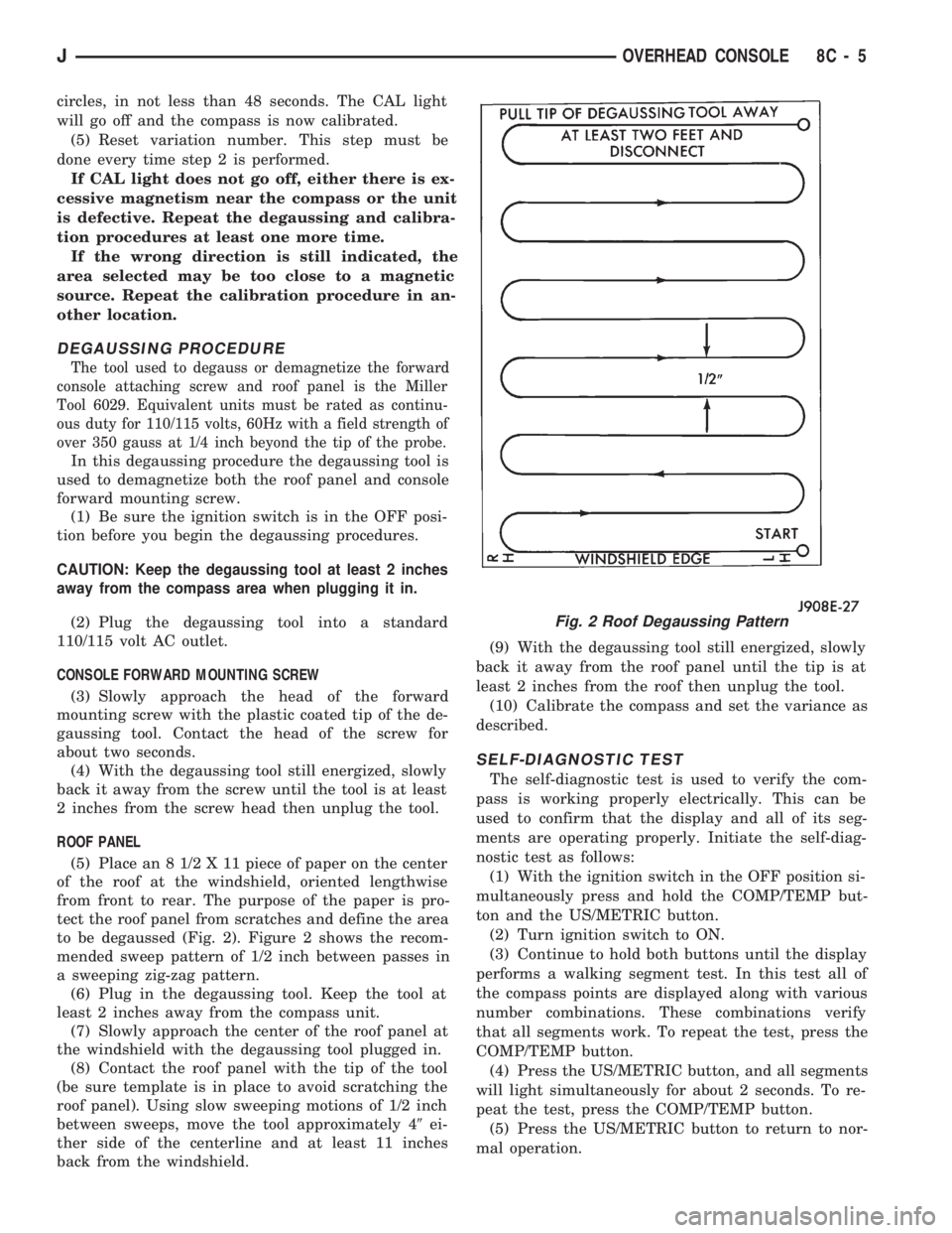
to be degaussed (Fig. 2). Figure 2 shows the recom-
mended sweep pattern of 1/2 inch between passes in
a sweeping zig-zag pattern.
(6) Plug in the degaussing tool. Keep the tool at
least 2 inches away from the compass unit.
(7) Slowly approach the center of the roof panel at
the windshield with the degaussing tool plugged in.
(8) Contact the roof panel with the tip of the tool
(be sure template is in place to avoid scratching the
roof panel). Using slow sweeping motions of 1/2 inch
between sweeps, move the tool approximately 49ei-
ther side of the centerline and at least 11 inches
back from the windshield.(9) With the degaussing tool still energized, slowly
back it away from the roof panel until the tip is at
least 2 inches from the roof then unplug the tool.
(10) Calibrate the compass and set the variance as
described.
SELF-DIAGNOSTIC TEST
The self-diagnostic test is used to verify the com-
pass is working properly electrically. This can be
used to confirm that the display and all of its seg-
ments are operating properly. Initiate the self-diag-
nostic test as follows:
(1) With the ignition switch in the OFF position si-
multaneously press and hold the COMP/TEMP but-
ton and the US/METRIC button.
(2) Turn ignition switch to ON.
(3) Continue to hold both buttons until the display
performs a walking segment test. In this test all of
the compass points are displayed along with various
number combinations. These combinations verify
that all segments work. To repeat the test, press the
COMP/TEMP button.
(4) Press the US/METRIC button, and all segments
will light simultaneously for about 2 seconds. To re-
peat the test, press the COMP/TEMP button.
(5) Press the US/METRIC button to return to nor-
mal operation.
Fig. 2 Roof Degaussing Pattern
JOVERHEAD CONSOLE 8C - 5
Page 330 of 1784
plugs with scavenger deposits can be considered nor-
mal in condition and can be cleaned using standard
procedures.
CHIPPED ELECTRODE INSULATOR
A chipped electrode insulator usually results from
bending the center electrode while adjusting the
spark plug electrode gap. Under certain conditions,
severe detonation can also separate the insulator
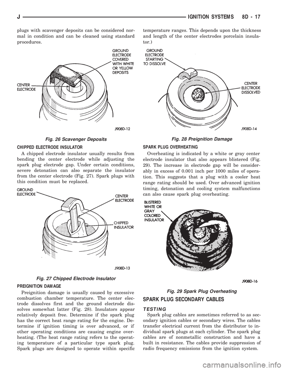
from the center electrode (Fig. 27). Spark plugs with
this condition must be replaced.
PREIGNITION DAMAGE
Preignition damage is usually caused by excessive
combustion chamber temperature. The center elec-
trode dissolves first and the ground electrode dis-
solves somewhat latter (Fig. 28). Insulators appear
relatively deposit free. Determine if the spark plug
has the correct heat range rating for the engine. De-
termine if ignition timing is over advanced, or if
other operating conditions are causing engine over-
heating. (The heat range rating refers to the operat-
ing temperature of a particular type spark plug.
Spark plugs are designed to operate within specifictemperature ranges. This depends upon the thickness
and length of the center electrodes porcelain insula-
tor.)
SPARK PLUG OVERHEATING
Overheating is indicated by a white or gray center
electrode insulator that also appears blistered (Fig.
29). The increase in electrode gap will be consider-
ably in excess of 0.001 inch per 1000 miles of opera-
tion. This suggests that a plug with a cooler heat
range rating should be used. Over advanced ignition
timing, detonation and cooling system malfunctions
can also cause spark plug overheating.
SPARK PLUG SECONDARY CABLES
TESTING
Spark plug cables are sometimes referred to as sec-
ondary ignition cables or secondary wires. The cables
transfer electrical current from the distributor to in-
dividual spark plugs at each cylinder. The spark plug
cables are of nonmetallic construction and have a
built in resistance. The cables provide suppression of
radio frequency emissions from the ignition system.
Fig. 26 Scavenger Deposits
Fig. 27 Chipped Electrode Insulator
Fig. 28 Preignition Damage
Fig. 29 Spark Plug Overheating
JIGNITION SYSTEMS 8D - 17
Page 331 of 1784
Check the high-tension cable connections for good
contact at the ignition coil, distributor cap towers
and spark plugs. Terminals should be fully seated.
The terminals and spark plug covers should be in
good condition. Terminals should fit tightly to the ig-
nition coil, distributor cap and spark plugs. The
spark plug cover (boot) of the cable should fit tight
around the spark plug insulator. Loose cable connec-
tions can cause corrosion and increase resistance, re-
sulting in shorter cable service life.
Clean the high tension cables with a cloth moist-
ened with a nonflammable solvent and wipe dry.
Check for brittle or cracked insulation.
When testing secondary cables for damage with an
oscilloscope, follow the instructions of the equipment
manufacturer.
If an oscilloscope is not available, spark plug cables
may be tested as follows:
CAUTION: Do not leave any one spark plug cable
disconnected for longer than necessary during test-
ing. This may cause possible heat damage to the
catalytic converter. Total test time must not exceed
ten minutes.
With the engine not running, connect one end of a
test probe to a good ground. Start the engine and run
the other end of the test probe along the entire
length of all spark plug cables. If cables are cracked
or punctured, there will be a noticeable spark jump
from the damaged area to the test probe. The cable
running from the ignition coil to the distributor cap
can be checked in the same manner. Cracked, dam-
aged or faulty cables should be replaced with resis-
tance type cable. This can be identified by the words
ELECTRONIC SUPPRESSION printed on the cable
jacket.
Use an ohmmeter to test for open circuits, exces-
sive resistance or loose terminals. Remove the dis-
tributor cap from the distributor.Do not remove
cables from cap.Remove cable from spark plug.
Connect ohmmeter to spark plug terminal end of ca-
ble and to corresponding electrode in distributor cap.
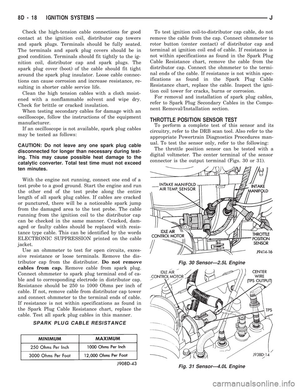
Resistance should be 250 to 1000 Ohms per inch of
cable. If not, remove cable from distributor cap tower
and connect ohmmeter to the terminal ends of cable.
If resistance is not within specifications as found in
the Spark Plug Cable Resistance chart, replace the
cable. Test all spark plug cables in this manner.To test ignition coil-to-distributor cap cable, do not
remove the cable from the cap. Connect ohmmeter to
rotor button (center contact) of distributor cap and
terminal at ignition coil end of cable. If resistance is
not within specifications as found in the Spark Plug
Cable Resistance chart, remove the cable from the
distributor cap. Connect the ohmmeter to the termi-
nal ends of the cable. If resistance is not within spec-
ifications as found in the Spark Plug Cable
Resistance chart, replace the cable. Inspect the igni-
tion coil tower for cracks, burns or corrosion.
For removal and installation of spark plug cables,
refer to Spark Plug Secondary Cables in the Compo-
nent Removal/Installation section.
THROTTLE POSITION SENSOR TEST
To perform a complete test of this sensor and its
circuitry, refer to the DRB scan tool. Also refer to the
appropriate Powertrain Diagnostics Procedures man-
ual. To test the sensor only, refer to the following:
The throttle position sensor can be tested with a
digital voltmeter. The center terminal of the sensor
connector is the output terminal (Figs. 30 or 31).
SPARK PLUG CABLE RESISTANCE
Fig. 30 SensorÐ2.5L Engine
Fig. 31 SensorÐ4.0L Engine
8D - 18 IGNITION SYSTEMSJ
Page 497 of 1784
FUSIBLE LINK REPLACEMENT
CAUTION: Do not replace blown fusible links with a
standard wire. Only use fusible type wire with hypa-
lon insulation or damage to the electrical system
could occur. Also make sure correct gauge of wir-
ing is used. Refer to the wiring diagrams for proper
gauge and color.
When a fusible link blows it is important to find
out what the problem is. They are placed in the elec-
trical system for protection against shorts to ground.
This can be caused by a component failure or various
wiring failures.Do not just replace the fusible
link to correct the problem.
When diagnosing a faulty fusible link it is impor-
tant to check the wire carefully. In some instances
the link may be blown and it will not show through
the insulation, the wire should be checked over its
entire length for internal breaks.
(1) Disconnect battery negative cable.
(2) Cut out the blown portion of the fusible link.
(3) Strip 1 inch of insulation from each end of the
existing fusible link.
(4) Place a piece of heat shrink tubing over one
side of the fusible link. Make sure the tubing will be
long enough to cover and seal the entire repair area.
(5) Cut a replacement piece of fusible link approx-
imately two inches longer than the piece removed.
(6) Remove one inch of insulation from each end of
the replacement fusible link.
(7) Spread the strands of wire apart on each of the
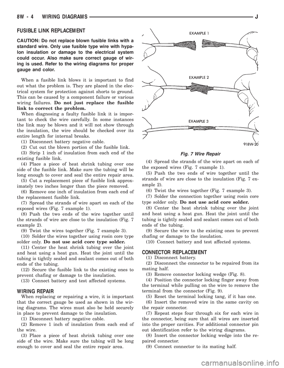
exposed wires (Fig. 7 example 1).
(8) Push the two ends of the wire together until
the strands of wire are close to the insulation (Fig. 7
example 2).
(9) Twist the wires together (Fig. 7 example 3).
(10) Solder the wires together using rosin core type
solder only.Do not use acid core type solder.
(11) Center the heat shrink tubing over the joint
and heat using a heat gun. Heat the joint until the
tubing is tightly sealed and sealant comes out of both
ends of the tubing.
(12) Secure the fusible link to the existing ones to
prevent chafing or damage to the insulation.
(13) Connect battery and test affected systems.
WIRING REPAIR
When replacing or repairing a wire, it is important
that the correct gauge be used as shown in the wir-
ing diagrams. The wires must also be held securely
in place to prevent damage to the insulation.
(1) Disconnect battery negative cable.
(2) Remove 1 inch of insulation from each end of
the wire.
(3) Place a piece of heat shrink tubing over one
side of the wire. Make sure the tubing will be long
enough to cover and seal the entire repair area.(4) Spread the strands of the wire apart on each of
the exposed wires (Fig. 7 example 1).
(5) Push the two ends of wire together until the
strands of wire are close to the insulation (Fig. 7 ex-
ample 2).
(6) Twist the wires together (Fig. 7 example 3).
(7) Solder the connection together using rosin core
type solder only.Do not use acid core solder.
(8) Center the heat shrink tubing over the joint
and heat using a heat gun. Heat the joint until the
tubing is tightly sealed and sealant comes out of both
ends of the tubing.
(9) Secure the wire to the existing ones to prevent
chafing or damage to the insulation.
(10) Connect battery and test affected systems.
CONNECTOR REPLACEMENT
(1) Disconnect battery.
(2) Disconnect the connector to be repaired from its
mating half.
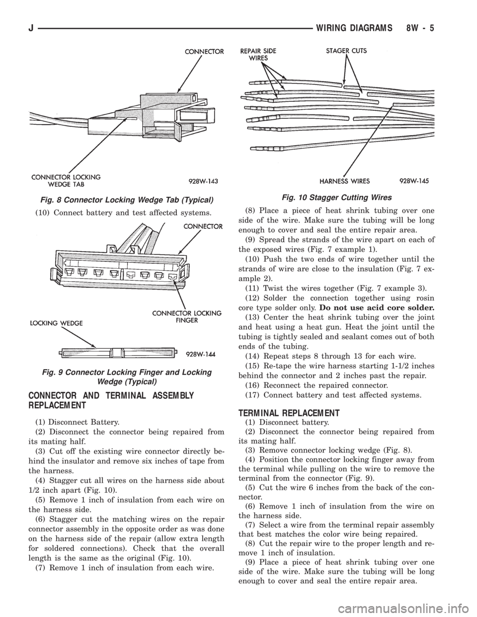
(3) Remove connector locking wedge (Fig. 8).
(4) Position the connector locking finger away from
the terminal while pulling on the wire to remove the
terminal from the connector (Fig. 9).
(5) Reset the terminal locking tang, if it has one.
(6) Insert the removed wire in the same cavity on
the repair connector.
(7) Repeat steps four through six for each wire in
the connector, being sure that all wires are inserted
into the proper cavities. For additional connector pin
out identification refer to the wiring diagrams.
(8) Insert the connector locking wedge into the re-
paired connector.
(9) Connect connector to its mating half.
Fig. 7 Wire Repair
8W - 4 WIRING DIAGRAMSJ
Page 498 of 1784
(10) Connect battery and test affected systems.
CONNECTOR AND TERMINAL ASSEMBLY
REPLACEMENT
(1) Disconnect Battery.
(2) Disconnect the connector being repaired from
its mating half.
(3) Cut off the existing wire connector directly be-
hind the insulator and remove six inches of tape from
the harness.
(4) Stagger cut all wires on the harness side about
1/2 inch apart (Fig. 10).
(5) Remove 1 inch of insulation from each wire on
the harness side.
(6) Stagger cut the matching wires on the repair
connector assembly in the opposite order as was done
on the harness side of the repair (allow extra length
for soldered connections). Check that the overall
length is the same as the original (Fig. 10).
(7) Remove 1 inch of insulation from each wire.(8) Place a piece of heat shrink tubing over one
side of the wire. Make sure the tubing will be long
enough to cover and seal the entire repair area.
(9) Spread the strands of the wire apart on each of
the exposed wires (Fig. 7 example 1).
(10) Push the two ends of wire together until the
strands of wire are close to the insulation (Fig. 7 ex-
ample 2).
(11) Twist the wires together (Fig. 7 example 3).
(12) Solder the connection together using rosin
core type solder only.Do not use acid core solder.
(13) Center the heat shrink tubing over the joint
and heat using a heat gun. Heat the joint until the
tubing is tightly sealed and sealant comes out of both
ends of the tubing.
(14) Repeat steps 8 through 13 for each wire.
(15) Re-tape the wire harness starting 1-1/2 inches
behind the connector and 2 inches past the repair.
(16) Reconnect the repaired connector.
(17) Connect battery and test affected systems.
TERMINAL REPLACEMENT
(1) Disconnect battery.
(2) Disconnect the connector being repaired from
its mating half.
(3) Remove connector locking wedge (Fig. 8).
(4) Position the connector locking finger away from
the terminal while pulling on the wire to remove the
terminal from the connector (Fig. 9).
(5) Cut the wire 6 inches from the back of the con-
nector.
(6) Remove 1 inch of insulation from the wire on
the harness side.
(7) Select a wire from the terminal repair assembly
that best matches the color wire being repaired.
(8) Cut the repair wire to the proper length and re-
move 1 inch of insulation.
(9) Place a piece of heat shrink tubing over one
side of the wire. Make sure the tubing will be long
enough to cover and seal the entire repair area.
Fig. 8 Connector Locking Wedge Tab (Typical)
Fig. 9 Connector Locking Finger and Locking
Wedge (Typical)
Fig. 10 Stagger Cutting Wires
JWIRING DIAGRAMS 8W - 5