length JEEP CHEROKEE 1994 Service Manual PDF
[x] Cancel search | Manufacturer: JEEP, Model Year: 1994, Model line: CHEROKEE, Model: JEEP CHEROKEE 1994Pages: 1784, PDF Size: 77.09 MB
Page 1537 of 1784
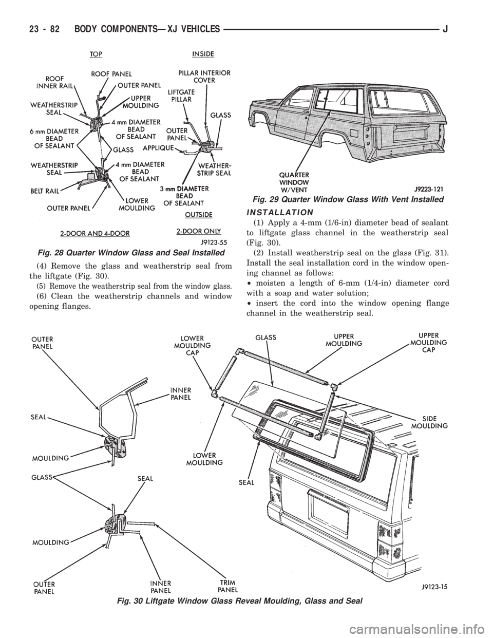
(4) Remove the glass and weatherstrip seal from
the liftgate (Fig. 30).
(5) Remove the weatherstrip seal from the window glass.
(6) Clean the weatherstrip channels and window
opening flanges.
INSTALLATION
(1) Apply a 4-mm (1/6-in) diameter bead of sealant
to liftgate glass channel in the weatherstrip seal
(Fig. 30).
(2) Install weatherstrip seal on the glass (Fig. 31).
Install the seal installation cord in the window open-
ing channel as follows:
²moisten a length of 6-mm (1/4-in) diameter cord
with a soap and water solution;
²insert the cord into the window opening flange
channel in the weatherstrip seal.
Fig. 29 Quarter Window Glass With Vent Installed
Fig. 30 Liftgate Window Glass Reveal Moulding, Glass and Seal
Fig. 28 Quarter Window Glass and Seal Installed
23 - 82 BODY COMPONENTSÐXJ VEHICLESJ
Page 1583 of 1784
SPARE TIRE/WHEEL HOLDDOWN AND FLOOR
BRACKETSÐXJ VEHICLES
REMOVAL
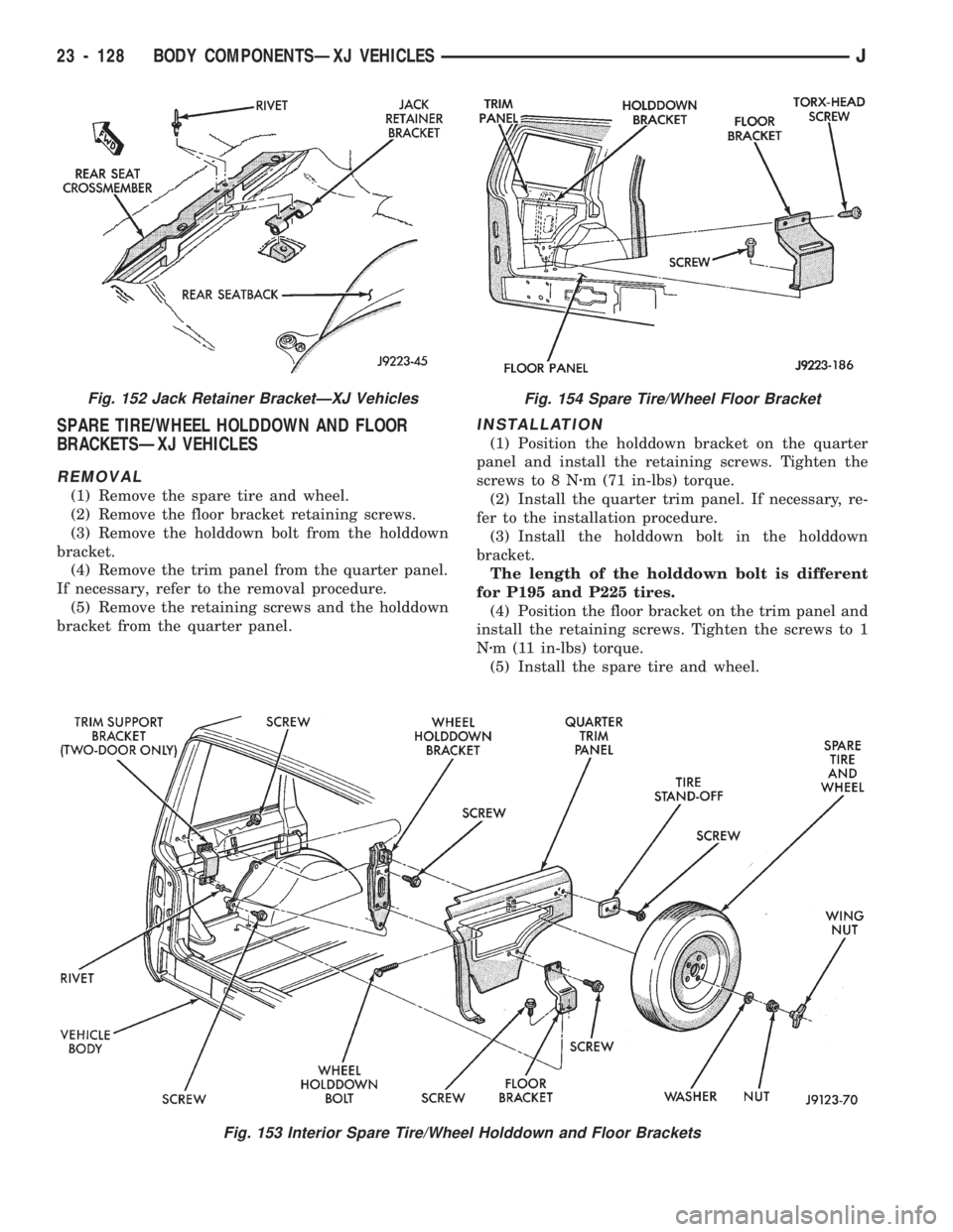
(1) Remove the spare tire and wheel.
(2) Remove the floor bracket retaining screws.
(3) Remove the holddown bolt from the holddown
bracket.
(4) Remove the trim panel from the quarter panel.
If necessary, refer to the removal procedure.
(5) Remove the retaining screws and the holddown
bracket from the quarter panel.
INSTALLATION
(1) Position the holddown bracket on the quarter
panel and install the retaining screws. Tighten the
screws to 8 Nzm (71 in-lbs) torque.
(2) Install the quarter trim panel. If necessary, re-
fer to the installation procedure.
(3) Install the holddown bolt in the holddown
bracket.
The length of the holddown bolt is different
for P195 and P225 tires.
(4) Position the floor bracket on the trim panel and
install the retaining screws. Tighten the screws to 1
Nzm (11 in-lbs) torque.
(5) Install the spare tire and wheel.
Fig. 153 Interior Spare Tire/Wheel Holddown and Floor Brackets
Fig. 152 Jack Retainer BracketÐXJ VehiclesFig. 154 Spare Tire/Wheel Floor Bracket
23 - 128 BODY COMPONENTSÐXJ VEHICLESJ
Page 1609 of 1784
The following equipment and material are neces-
sary for body stripe/decal removal and installation:
²a commercial tape stripe/decal removal solution;
²a commercial adhesive removal solution;
²liquid dish detergent (for the wetting solution);
²a mixture of wetting solution;
²a commercial wax and silicone removal solution;
²isopropyl (rubbing) alcohol;
²a small squeegee (plastic or hard rubber);
²a water bucket and sponge;
²clean wiping rags or paper towels;
²a heat gun (or infra-red heat bulb);
²a wax pencil;
²a sharp knife, single edge razor blade or X-acto
knife;
²a pair of scissors; and
²a needle or pin.
A wetting solution assures a better bond between
the painted surface of the body and the tape stripe/
decal. Prepare a supply of wetting solution by mixing
two or three teaspoons of dish detergent with 1 gal-
lon of water.Do not use soap.
Too much detergent will reduce the effective-
ness of the mixture.
REMOVAL
The key to successful tape stripe/decal re-
moval is to apply heat to area and slowly peel
stripe/decal from panel.
(1) Clean the repaired surface, adjacent panels and
door openings as necessary.
(2) Start at one end of the tape stripe/decal and
apply heat with a heat gun. Slowly peel the stripe/
decal from the panel by pulling it back.Do not pull
the tape stripe/decal outward from the panel.
WARNING: USE THE TAPE STRIPE/DECAL RE-
MOVAL SOLUTION IN A WELL-VENTILATED AREA
ONLY.
(3) A commercial tape stripe/decal removal solution
can be used for stripe/decal removal at areas where a
heat gun is ineffective:
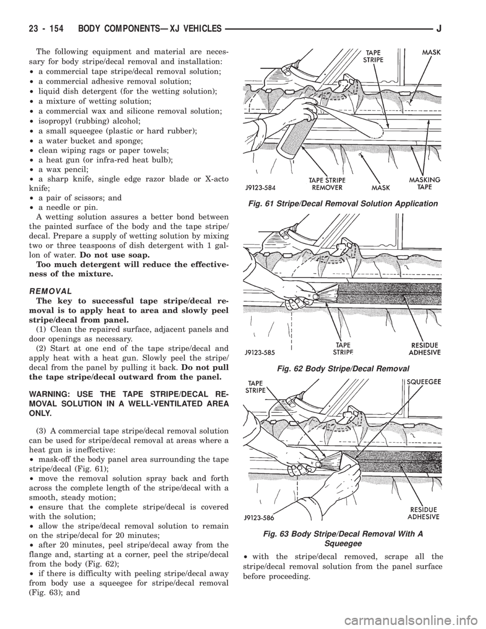
²mask-off the body panel area surrounding the tape
stripe/decal (Fig. 61);
²move the removal solution spray back and forth
across the complete length of the stripe/decal with a
smooth, steady motion;
²ensure that the complete stripe/decal is covered
with the solution;
²allow the stripe/decal removal solution to remain
on the stripe/decal for 20 minutes;
²after 20 minutes, peel stripe/decal away from the
flange and, starting at a corner, peel the stripe/decal
from the body (Fig. 62);
²if there is difficulty with peeling stripe/decal away
from body use a squeegee for stripe/decal removal
(Fig. 63); and²with the stripe/decal removed, scrape all the
stripe/decal removal solution from the panel surface
before proceeding.
Fig. 61 Stripe/Decal Removal Solution Application
Fig. 62 Body Stripe/Decal Removal
Fig. 63 Body Stripe/Decal Removal With A
Squeegee
23 - 154 BODY COMPONENTSÐXJ VEHICLESJ
Page 1610 of 1784
WARNING: USE THE ADHESIVE REMOVAL SOLU-
TION IN A WELL-VENTILATED AREA ONLY.
(4) After the stripe/decal is removed, remove any
adhesive remaining on body with a removal solution.
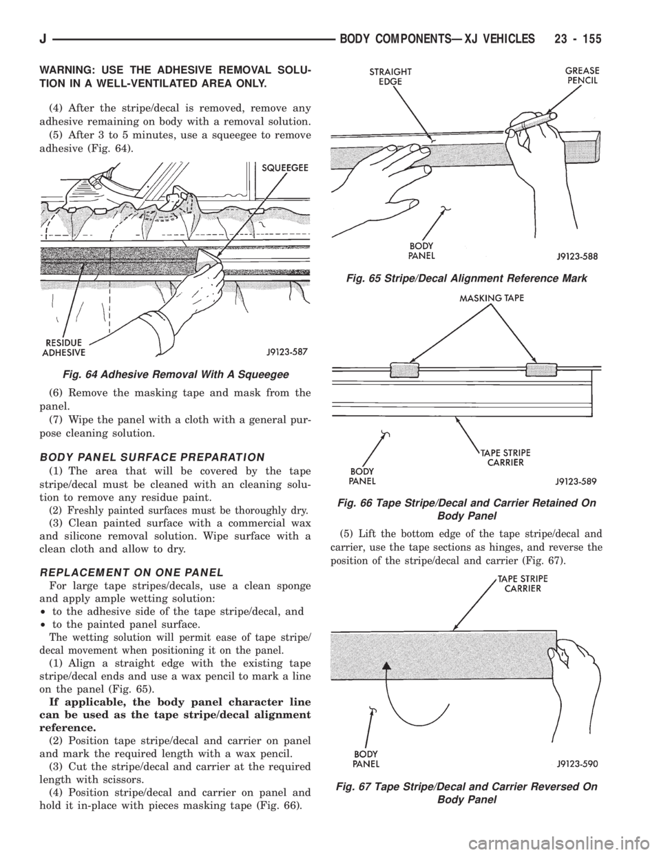
(5) After 3 to 5 minutes, use a squeegee to remove
adhesive (Fig. 64).
(6) Remove the masking tape and mask from the
panel.
(7) Wipe the panel with a cloth with a general pur-
pose cleaning solution.
BODY PANEL SURFACE PREPARATION
(1) The area that will be covered by the tape
stripe/decal must be cleaned with an cleaning solu-
tion to remove any residue paint.
(2) Freshly painted surfaces must be thoroughly dry.
(3) Clean painted surface with a commercial wax
and silicone removal solution. Wipe surface with a
clean cloth and allow to dry.
REPLACEMENT ON ONE PANEL
For large tape stripes/decals, use a clean sponge
and apply ample wetting solution:
²to the adhesive side of the tape stripe/decal, and
²to the painted panel surface.
The wetting solution will permit ease of tape stripe/
decal movement when positioning it on the panel.
(1) Align a straight edge with the existing tape
stripe/decal ends and use a wax pencil to mark a line
on the panel (Fig. 65).
If applicable, the body panel character line
can be used as the tape stripe/decal alignment
reference.
(2) Position tape stripe/decal and carrier on panel
and mark the required length with a wax pencil.
(3) Cut the stripe/decal and carrier at the required
length with scissors.
(4) Position stripe/decal and carrier on panel and
hold it in-place with pieces masking tape (Fig. 66).
(5) Lift the bottom edge of the tape stripe/decal and
carrier, use the tape sections as hinges, and reverse the
position of the stripe/decal and carrier (Fig. 67).
Fig. 65 Stripe/Decal Alignment Reference Mark
Fig. 66 Tape Stripe/Decal and Carrier Retained On
Body Panel
Fig. 67 Tape Stripe/Decal and Carrier Reversed On
Body Panel
Fig. 64 Adhesive Removal With A Squeegee
JBODY COMPONENTSÐXJ VEHICLES 23 - 155
Page 1637 of 1784
(7) Attach the window glass to the regulator arm
guide (Fig. 12).
(8) Install the beltline weatherstrip seals in the
door (Fig. 18).
(9) Position the latch in the door and install the re-
taining screws (Fig. 15). Tighten the screws securely.
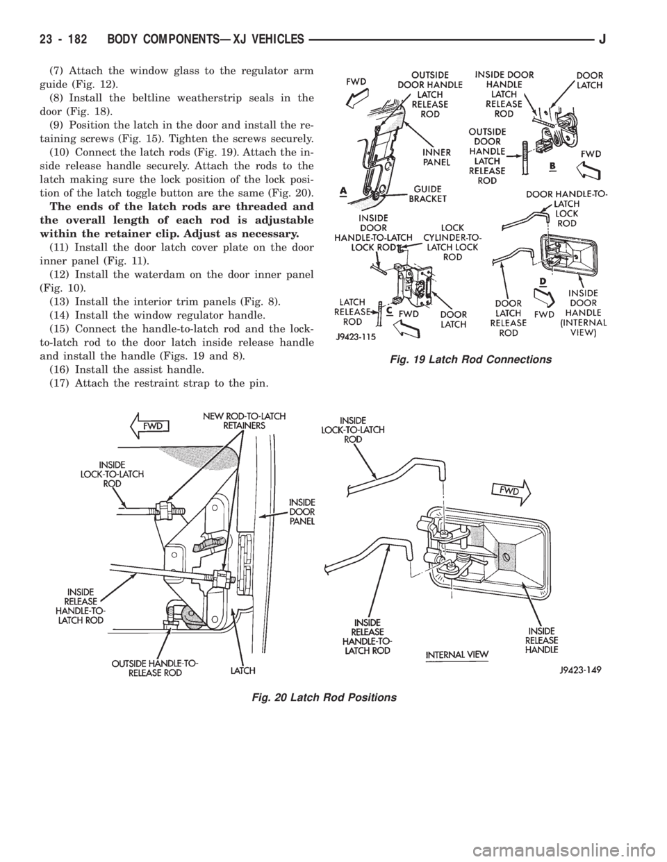
(10) Connect the latch rods (Fig. 19). Attach the in-
side release handle securely. Attach the rods to the
latch making sure the lock position of the lock posi-
tion of the latch toggle button are the same (Fig. 20).
The ends of the latch rods are threaded and
the overall length of each rod is adjustable
within the retainer clip. Adjust as necessary.
(11) Install the door latch cover plate on the door
inner panel (Fig. 11).
(12) Install the waterdam on the door inner panel
(Fig. 10).
(13) Install the interior trim panels (Fig. 8).
(14) Install the window regulator handle.
(15) Connect the handle-to-latch rod and the lock-
to-latch rod to the door latch inside release handle
and install the handle (Figs. 19 and 8).
(16) Install the assist handle.
(17) Attach the restraint strap to the pin.
Fig. 20 Latch Rod Positions
Fig. 19 Latch Rod Connections
23 - 182 BODY COMPONENTSÐXJ VEHICLESJ
Page 1659 of 1784
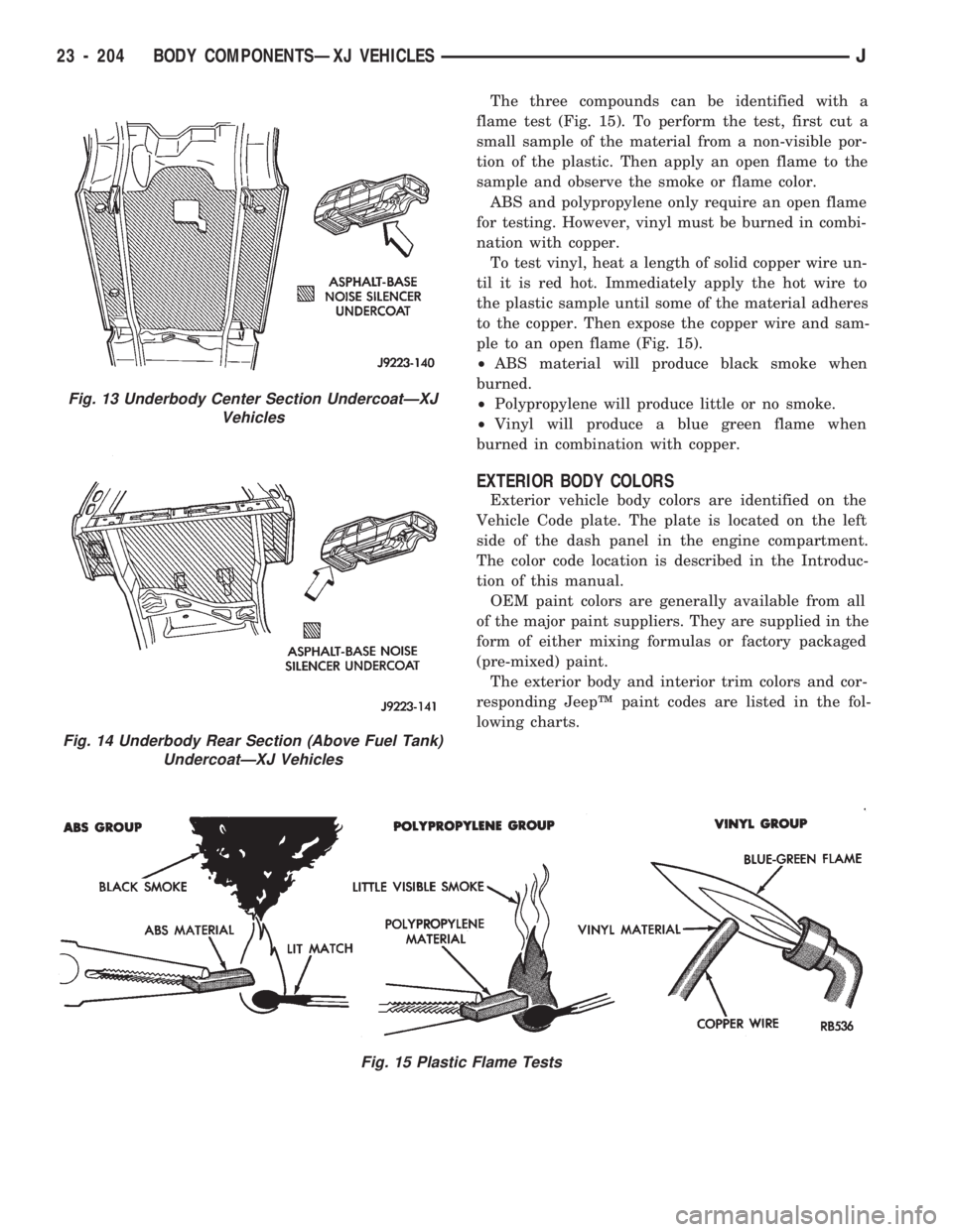
The three compounds can be identified with a
flame test (Fig. 15). To perform the test, first cut a
small sample of the material from a non-visible por-
tion of the plastic. Then apply an open flame to the
sample and observe the smoke or flame color.
ABS and polypropylene only require an open flame
for testing. However, vinyl must be burned in combi-
nation with copper.
To test vinyl, heat a length of solid copper wire un-
til it is red hot. Immediately apply the hot wire to
the plastic sample until some of the material adheres
to the copper. Then expose the copper wire and sam-
ple to an open flame (Fig. 15).
²ABS material will produce black smoke when
burned.
²Polypropylene will produce little or no smoke.
²Vinyl will produce a blue green flame when
burned in combination with copper.
EXTERIOR BODY COLORS
Exterior vehicle body colors are identified on the
Vehicle Code plate. The plate is located on the left
side of the dash panel in the engine compartment.
The color code location is described in the Introduc-
tion of this manual.
OEM paint colors are generally available from all
of the major paint suppliers. They are supplied in the
form of either mixing formulas or factory packaged
(pre-mixed) paint.
The exterior body and interior trim colors and cor-
responding JeepŸ paint codes are listed in the fol-
lowing charts.
Fig. 15 Plastic Flame Tests
Fig. 13 Underbody Center Section UndercoatÐXJ
Vehicles
Fig. 14 Underbody Rear Section (Above Fuel Tank)
UndercoatÐXJ Vehicles
23 - 204 BODY COMPONENTSÐXJ VEHICLESJ