spark plugs replace JEEP CHEROKEE 1994 Service User Guide
[x] Cancel search | Manufacturer: JEEP, Model Year: 1994, Model line: CHEROKEE, Model: JEEP CHEROKEE 1994Pages: 1784, PDF Size: 77.09 MB
Page 845 of 1784
CONNECTING ROD BEARING CLEARANCE
Engine connecting rod bearing clearances can be
determined by use of Plastigage, or equivalent. The
following is the recommended procedures for the use
of Plastigage:
(1) Remove oil film from surface to be checked.
Plastigage is soluble in oil.
(2) Place a piece of Plastigage across the entire
width of the bearing cap shell (Fig. 2). Position the
Plastigage approximately 6.35 mm (1/4 inch) off cen-
ter and away from the oil holes. In addition, suspect
areas can be checked by placing the Plastigage in the
suspect area.
(3) The crankshaft must be turned until the con-
necting rod to be checked starts moving toward the
top of the engine. Only then should the rod cap with
Plastigage in place be assembled. Tighten the rod
cap nut to 45 Nzm (33 ft. lbs.) torque.DO NOT ro-
tate the crankshaft or the Plastigage may be
smeared, giving inaccurate results.
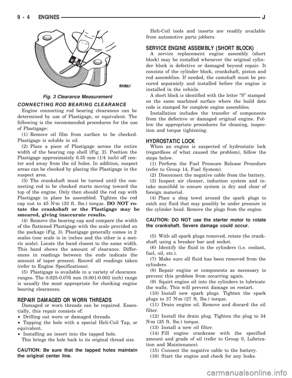
(4) Remove the bearing cap and compare the width
of the flattened Plastigage with the scale provided on
the package (Fig. 3). Plastigage generally comes in 2
scales (one scale is in inches and the other is a met-
ric scale). Locate the band closest to the same width.
This band shows the amount of clearance. Differ-
ences in readings between the ends indicate the
amount of taper present. Record all readings taken
(refer to Engine Specifications).
(5) Plastigage is available in a variety of clearance
ranges. The 0.025-0.076 mm (0.001-0.003 inch) range
is usually the most appropriate for checking engine
bearing clearances.
REPAIR DAMAGED OR WORN THREADS
Damaged or worn threads can be repaired. Essen-
tially, this repair consists of:
²Drilling out worn or damaged threads.
²Tapping the hole with a special Heli-Coil Tap, or
equivalent.
²Installing an insert into the tapped hole.
This brings the hole back to its original thread size.
CAUTION: Be sure that the tapped holes maintain
the original center line.Heli-Coil tools and inserts are readily available
from automotive parts jobbers.
SERVICE ENGINE ASSEMBLY (SHORT BLOCK)
A service replacement engine assembly (short
block) may be installed whenever the original cylin-
der block is defective or damaged beyond repair. It
consists of the cylinder block, crankshaft, piston and
rod assemblies. If needed, the camshaft must be pro-
cured separately and installed before the engine is
installed in the vehicle.
A short block is identified with the letter ``S'' stamped
on the same machined surface where the build date
code is stamped for complete engine assemblies.
Installation includes the transfer of components
from the defective or damaged original engine. Fol-
low the appropriate procedures for cleaning, inspec-
tion and torque tightening.
HYDROSTATIC LOCK
When an engine is suspected of hydrostatic lock
(regardless of what caused the problem), follow the
steps below.
(1) Perform the Fuel Pressure Release Procedure
(refer to Group 14, Fuel System).
(2) Disconnect the negative cable from the battery.
(3) Inspect air cleaner, induction system and in-
take manifold to ensure system is dry and clear of
foreign material.
(4) Place a shop towel around the spark plugs to
catch any fluid that may possibly be under pressure in
the cylinder head. Remove the plugs from the engine.
CAUTION: DO NOT use the starter motor to rotate
the crankshaft. Severe damage could occur.
(5) With all spark plugs removed, rotate the crank-
shaft using a breaker bar and socket.
(6) Identify the fluid in the cylinders (i.e. coolant,
fuel, oil, etc.).
(7) Make sure all fluid has been removed from the
cylinders.
(8) Repair engine or components as necessary to
prevent this problem from occurring again.
(9) Squirt engine oil into the cylinders to lubricate
the walls. This will prevent damage on restart.
(10) Install new spark plugs. Tighten the spark
plugs to 37 Nzm (27 ft. lbs.) torque.
(11) Drain engine oil. Remove and discard the oil
filter.
(12) Install the drain plug. Tighten the plug to 34
Nzm (25 ft. lbs.) torque.
(13) Install a new oil filter.
(14) Fill engine crankcase with the specified
amount and grade of oil (refer to Group 0, Lubrica-
tion and Maintenance).
(15) Connect the negative cable to the battery.
(16) Start the engine and check for any leaks.
Fig. 3 Clearance Measurement
9 - 4 ENGINESJ
Page 861 of 1784
(a) Remove the bolts from the A/C compressor
mounting bracket and set the compressor aside.
(b) Remove the air conditioner compressor
bracket bolts from the engine cylinder head.
(c) Loosen the through bolt at the bottom of the
bracket.
(9) If equipped, disconnect the power steering
pump bracket. Set the pump and bracket aside. DO
NOT disconnect the hoses.
(10) Remove the fuel lines and vacuum advance
hose.
(11) Remove the intake and engine exhaust mani-
folds from the engine cylinder head (refer to Group
11, Exhaust System and Intake Manifold for the
proper procedures).
(12) Disconnect the ignition wires and remove the
spark plugs.
(13) Disconnect the temperature sending unit wire
connector.
(14) Remove the ignition coil and bracket assem-
bly.
(15) Remove the engine cylinder head bolts.
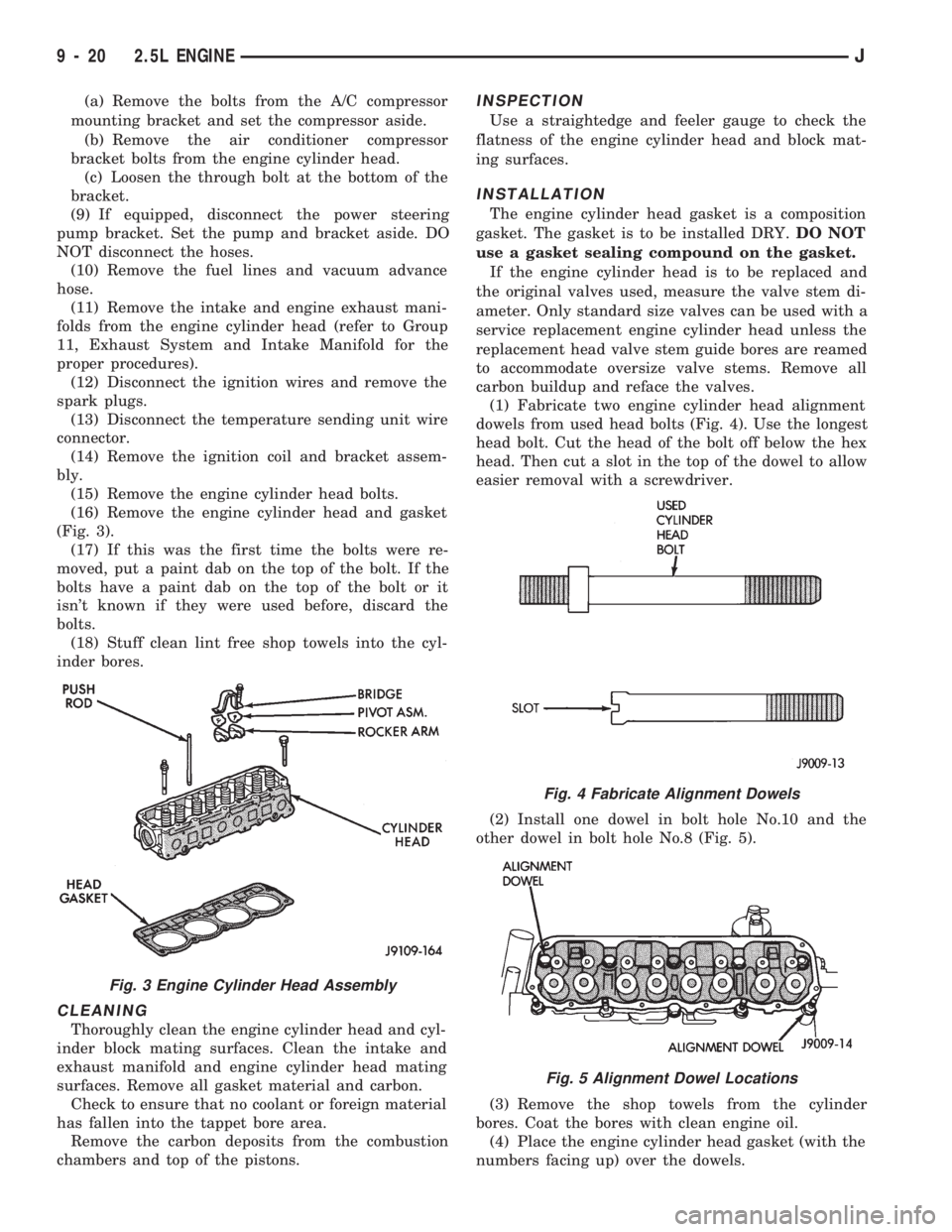
(16) Remove the engine cylinder head and gasket
(Fig. 3).
(17) If this was the first time the bolts were re-
moved, put a paint dab on the top of the bolt. If the
bolts have a paint dab on the top of the bolt or it
isn't known if they were used before, discard the
bolts.
(18) Stuff clean lint free shop towels into the cyl-
inder bores.
CLEANING
Thoroughly clean the engine cylinder head and cyl-
inder block mating surfaces. Clean the intake and
exhaust manifold and engine cylinder head mating
surfaces. Remove all gasket material and carbon.
Check to ensure that no coolant or foreign material
has fallen into the tappet bore area.
Remove the carbon deposits from the combustion
chambers and top of the pistons.
INSPECTION
Use a straightedge and feeler gauge to check the
flatness of the engine cylinder head and block mat-
ing surfaces.
INSTALLATION
The engine cylinder head gasket is a composition
gasket. The gasket is to be installed DRY.DO NOT
use a gasket sealing compound on the gasket.
If the engine cylinder head is to be replaced and
the original valves used, measure the valve stem di-
ameter. Only standard size valves can be used with a
service replacement engine cylinder head unless the
replacement head valve stem guide bores are reamed
to accommodate oversize valve stems. Remove all
carbon buildup and reface the valves.
(1) Fabricate two engine cylinder head alignment
dowels from used head bolts (Fig. 4). Use the longest
head bolt. Cut the head of the bolt off below the hex
head. Then cut a slot in the top of the dowel to allow
easier removal with a screwdriver.
(2) Install one dowel in bolt hole No.10 and the
other dowel in bolt hole No.8 (Fig. 5).
(3) Remove the shop towels from the cylinder
bores. Coat the bores with clean engine oil.
(4) Place the engine cylinder head gasket (with the
numbers facing up) over the dowels.
Fig. 3 Engine Cylinder Head Assembly
Fig. 4 Fabricate Alignment Dowels
Fig. 5 Alignment Dowel Locations
9 - 20 2.5L ENGINEJ
Page 862 of 1784
(5) Place the engine cylinder head over the dowels.
CAUTION: Engine cylinder head bolts should be re-
used only once. Replace the head bolts if they were
used before or if they have a paint dab on the top
of the bolt.
(6) Coat the threads of bolt No.7, only, with Loctite
PST sealant or equivalent.
(7) Install all head bolts, except No.8 and No.10.
(8) Remove the dowels.
(9) Install No.8 and No.10 head bolts.
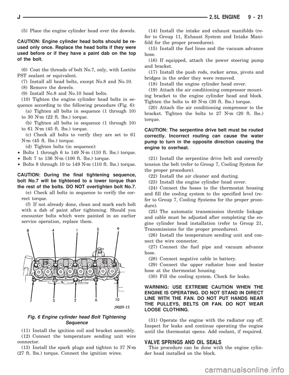
(10) Tighten the engine cylinder head bolts in se-
quence according to the following procedure (Fig. 6):
(a) Tighten all bolts in sequence (1 through 10)
to 30 Nzm (22 ft. lbs.) torque.
(b) Tighten all bolts in sequence (1 through 10)
to 61 Nzm (45 ft. lbs.) torque.
(c) Check all bolts to verify they are set to 61
Nzm (45 ft. lbs.) torque.
(d) Tighten bolts (in sequence):
²Bolts 1 through 6 to 149 Nzm (110 ft. lbs.) torque.
²Bolt 7 to 136 Nzm (100 ft. lbs.) torque.
²Bolts 8 through 10 to 149 Nzm (110 ft. lbs.) torque.
CAUTION: During the final tightening sequence,
bolt No.7 will be tightened to a lower torque than
the rest of the bolts. DO NOT overtighten bolt No.7.
(e) Check all bolts in sequence to verify the cor-
rect torque.
(f) If not already done, clean and mark each bolt
with a dab of paint after tightening. Should you
encounter bolts which were painted in an earlier
service operation, replace them.
(11) Install the ignition coil and bracket assembly.
(12) Connect the temperature sending unit wire
connector.
(13) Install the spark plugs and tighten to 37 Nzm
(27 ft. lbs.) torque. Connect the ignition wires.(14) Install the intake and exhaust manifolds (re-
fer to Group 11, Exhaust System and Intake Mani-
fold for the proper procedures).
(15) Install the fuel lines and the vacuum advance
hose.
(16) If equipped, attach the power steering pump
and bracket.
(17) Install the push rods, rocker arms, pivots and
bridges in the order they were removed.
(18) Install the engine cylinder head cover.
(19) Attach the air conditioning compressor mount-
ing bracket to the engine cylinder head and block.
Tighten the bolts to 40 Nzm (30 ft. lbs.) torque.
(20) Attach the air conditioning compressor to the
bracket. Tighten the bolts to 27 Nzm (20 ft. lbs.)
torque.
CAUTION: The serpentine drive belt must be routed
correctly. Incorrect routing can cause the water
pump to turn in the opposite direction causing the
engine to overheat.
(21) Install the serpentine drive belt and correctly
tension the belt (refer to Group 7, Cooling System for
the proper procedure).
(22) Install the air cleaner and ducting.
(23) Install the engine cylinder head cover.
(24) Connect the hoses to the thermostat housing
and fill the cooling system to the specified level (re-
fer to Group 7, Cooling Systems for the proper proce-
dure).
(25) The automatic transmission throttle linkage
and cable must be adjusted after completing the en-
gine cylinder head installation (refer to Group 21,
Transmissions for the proper procedures).
(26) Install the temperature sending unit and con-
nect the wire connector.
(27) Connect the fuel pipe and vacuum advance
hose.
(28) Connect negative cable to battery.
(29) Connect the upper radiator hose and heater
hose at the thermostat housing.
(30) Fill the cooling system. Check for leaks.
WARNING: USE EXTREME CAUTION WHEN THE
ENGINE IS OPERATING. DO NOT STAND IN DIRECT
LINE WITH THE FAN. DO NOT PUT HANDS NEAR
THE PULLEYS, BELTS OR FAN. DO NOT WEAR
LOOSE CLOTHING.
(31) Operate the engine with the radiator cap off.
Inspect for leaks and continue operating the engine
until the thermostat opens. Add coolant, if required.
VALVE SPRINGS AND OIL SEALS
This procedure can be done with the engine cylin-
der head installed on the block.
Fig. 6 Engine cylinder head Bolt Tightening
Sequence
J2.5L ENGINE 9 - 21
Page 867 of 1784
least 1 600 km (1,000 miles). The oil supplement
need not be drained until the next scheduled oil
change.
(7) Install the engine cylinder head cover.
VALVE TIMING
Disconnect the spark plug wires and remove the
spark plugs.
Remove the engine cylinder head cover.
Remove the capscrews, bridge and pivot assembly,
and rocker arms from above the No.1 cylinder.
Alternately loosen each capscrew, one turn at a
time, to avoid damaging the bridge.
Rotate the crankshaft until the No.4 piston is at
top dead center (TDC) on the compression stroke.
Rotate the crankshaft counterclockwise (viewed
from the front of the engine) 90É.
Install a dial indicator on the end of the No.1 cyl-
inder intake valve push rod. Use rubber tubing to se-
cure the indicator stem on the push rod.
Set the dial indicator pointer at zero.
Rotate the crankshaft clockwise (viewed from the
front of the engine) until the dial indicator pointer
indicates 0.305 mm (0.012 inch) travel distance (lift).
The timing notch index on the vibration damper
should be aligned with the TDC mark on the timing
degree scale.
If the timing notch is more than 13 mm (1/2 inch)
away from the TDC mark in either direction, the
valve timing is incorrect.
If the valve timing is incorrect, the cause may be a
broken camshaft pin. It is not necessary to replace
the camshaft because of pin failure. A spring pin is
available for service replacement.
VIBRATION DAMPER
REMOVAL
(1) Disconnect negative cable from battery.
(2) Remove the serpentine drive belt and fan
shroud.
(3) Remove the vibration damper retaining bolt
and washer.
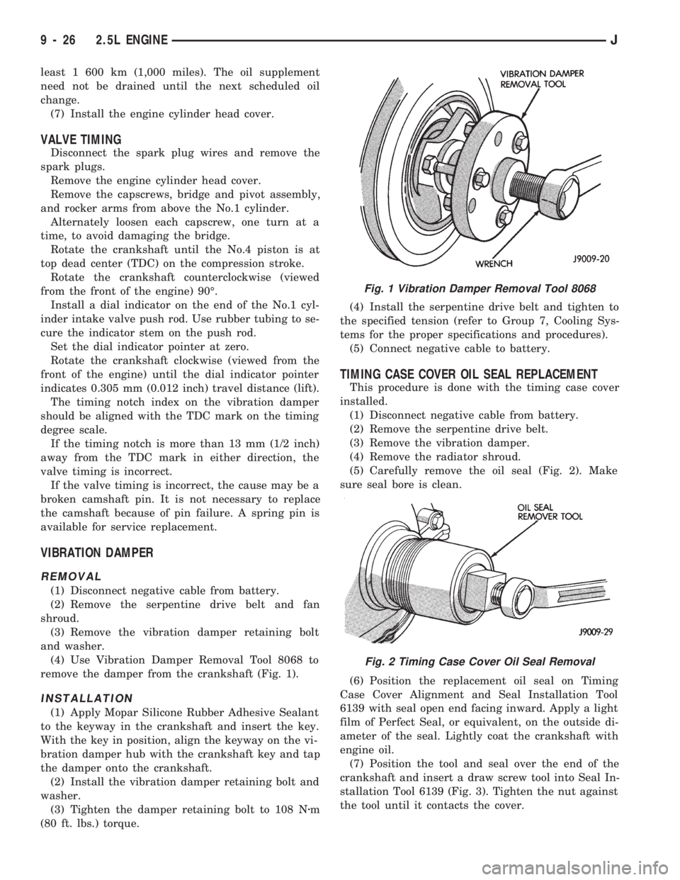
(4) Use Vibration Damper Removal Tool 8068 to
remove the damper from the crankshaft (Fig. 1).
INSTALLATION
(1) Apply Mopar Silicone Rubber Adhesive Sealant
to the keyway in the crankshaft and insert the key.
With the key in position, align the keyway on the vi-
bration damper hub with the crankshaft key and tap
the damper onto the crankshaft.
(2) Install the vibration damper retaining bolt and
washer.
(3) Tighten the damper retaining bolt to 108 Nzm
(80 ft. lbs.) torque.(4) Install the serpentine drive belt and tighten to
the specified tension (refer to Group 7, Cooling Sys-
tems for the proper specifications and procedures).
(5) Connect negative cable to battery.
TIMING CASE COVER OIL SEAL REPLACEMENT
This procedure is done with the timing case cover
installed.
(1) Disconnect negative cable from battery.
(2) Remove the serpentine drive belt.
(3) Remove the vibration damper.
(4) Remove the radiator shroud.
(5) Carefully remove the oil seal (Fig. 2). Make
sure seal bore is clean.
(6) Position the replacement oil seal on Timing
Case Cover Alignment and Seal Installation Tool
6139 with seal open end facing inward. Apply a light
film of Perfect Seal, or equivalent, on the outside di-
ameter of the seal. Lightly coat the crankshaft with
engine oil.
(7) Position the tool and seal over the end of the
crankshaft and insert a draw screw tool into Seal In-
stallation Tool 6139 (Fig. 3). Tighten the nut against
the tool until it contacts the cover.
Fig. 1 Vibration Damper Removal Tool 8068
Fig. 2 Timing Case Cover Oil Seal Removal
9 - 26 2.5L ENGINEJ
Page 885 of 1784
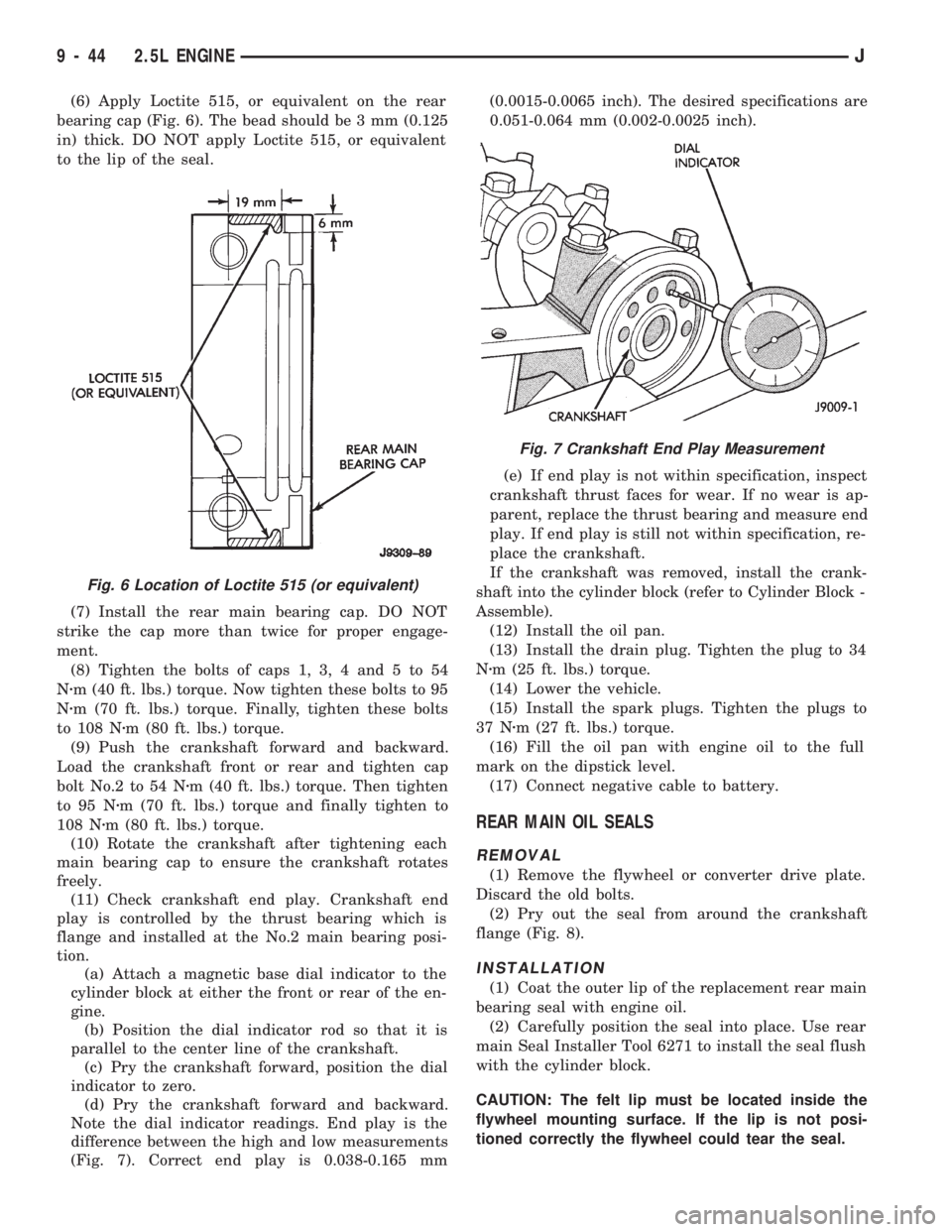
(6) Apply Loctite 515, or equivalent on the rear
bearing cap (Fig. 6). The bead should be 3 mm (0.125
in) thick. DO NOT apply Loctite 515, or equivalent
to the lip of the seal.
(7) Install the rear main bearing cap. DO NOT
strike the cap more than twice for proper engage-
ment.
(8) Tighten the bolts of caps 1, 3, 4 and 5 to 54
Nzm (40 ft. lbs.) torque. Now tighten these bolts to 95
Nzm (70 ft. lbs.) torque. Finally, tighten these bolts
to 108 Nzm (80 ft. lbs.) torque.
(9) Push the crankshaft forward and backward.
Load the crankshaft front or rear and tighten cap
bolt No.2 to 54 Nzm (40 ft. lbs.) torque. Then tighten
to 95 Nzm (70 ft. lbs.) torque and finally tighten to
108 Nzm (80 ft. lbs.) torque.
(10) Rotate the crankshaft after tightening each
main bearing cap to ensure the crankshaft rotates
freely.
(11) Check crankshaft end play. Crankshaft end
play is controlled by the thrust bearing which is
flange and installed at the No.2 main bearing posi-
tion.
(a) Attach a magnetic base dial indicator to the
cylinder block at either the front or rear of the en-
gine.
(b) Position the dial indicator rod so that it is
parallel to the center line of the crankshaft.
(c) Pry the crankshaft forward, position the dial
indicator to zero.
(d) Pry the crankshaft forward and backward.
Note the dial indicator readings. End play is the
difference between the high and low measurements
(Fig. 7). Correct end play is 0.038-0.165 mm(0.0015-0.0065 inch). The desired specifications are
0.051-0.064 mm (0.002-0.0025 inch).
(e) If end play is not within specification, inspect
crankshaft thrust faces for wear. If no wear is ap-
parent, replace the thrust bearing and measure end
play. If end play is still not within specification, re-
place the crankshaft.
If the crankshaft was removed, install the crank-
shaft into the cylinder block (refer to Cylinder Block -
Assemble).
(12) Install the oil pan.
(13) Install the drain plug. Tighten the plug to 34
Nzm (25 ft. lbs.) torque.
(14) Lower the vehicle.
(15) Install the spark plugs. Tighten the plugs to
37 Nzm (27 ft. lbs.) torque.
(16) Fill the oil pan with engine oil to the full
mark on the dipstick level.
(17) Connect negative cable to battery.
REAR MAIN OIL SEALS
REMOVAL
(1) Remove the flywheel or converter drive plate.
Discard the old bolts.
(2) Pry out the seal from around the crankshaft
flange (Fig. 8).
INSTALLATION
(1) Coat the outer lip of the replacement rear main
bearing seal with engine oil.
(2) Carefully position the seal into place. Use rear
main Seal Installer Tool 6271 to install the seal flush
with the cylinder block.
CAUTION: The felt lip must be located inside the
flywheel mounting surface. If the lip is not posi-
tioned correctly the flywheel could tear the seal.
Fig. 6 Location of Loctite 515 (or equivalent)
Fig. 7 Crankshaft End Play Measurement
9 - 44 2.5L ENGINEJ
Page 902 of 1784
(11) Remove the intake and engine exhaust mani-
folds from the engine cylinder head (refer to Group
11, Exhaust System and Intake Manifold for the
proper procedures).
(12) Disconnect the ignition wires and remove the
spark plugs.
(13) Disconnect the temperature sending unit wire
connector.
(14) Remove the ignition coil and bracket assem-
bly.
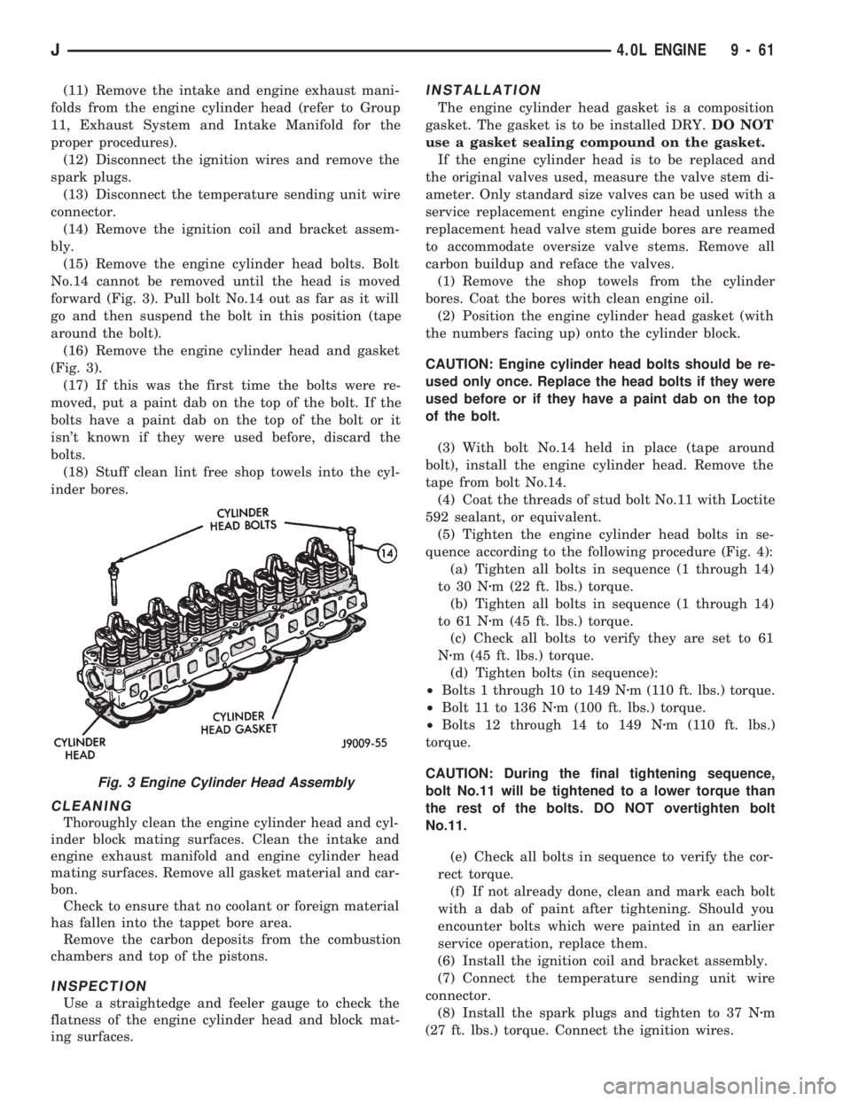
(15) Remove the engine cylinder head bolts. Bolt
No.14 cannot be removed until the head is moved
forward (Fig. 3). Pull bolt No.14 out as far as it will
go and then suspend the bolt in this position (tape
around the bolt).
(16) Remove the engine cylinder head and gasket
(Fig. 3).
(17) If this was the first time the bolts were re-
moved, put a paint dab on the top of the bolt. If the
bolts have a paint dab on the top of the bolt or it
isn't known if they were used before, discard the
bolts.
(18) Stuff clean lint free shop towels into the cyl-
inder bores.
CLEANING
Thoroughly clean the engine cylinder head and cyl-
inder block mating surfaces. Clean the intake and
engine exhaust manifold and engine cylinder head
mating surfaces. Remove all gasket material and car-
bon.
Check to ensure that no coolant or foreign material
has fallen into the tappet bore area.
Remove the carbon deposits from the combustion
chambers and top of the pistons.
INSPECTION
Use a straightedge and feeler gauge to check the
flatness of the engine cylinder head and block mat-
ing surfaces.
INSTALLATION
The engine cylinder head gasket is a composition
gasket. The gasket is to be installed DRY.DO NOT
use a gasket sealing compound on the gasket.
If the engine cylinder head is to be replaced and
the original valves used, measure the valve stem di-
ameter. Only standard size valves can be used with a
service replacement engine cylinder head unless the
replacement head valve stem guide bores are reamed
to accommodate oversize valve stems. Remove all
carbon buildup and reface the valves.
(1) Remove the shop towels from the cylinder
bores. Coat the bores with clean engine oil.
(2) Position the engine cylinder head gasket (with
the numbers facing up) onto the cylinder block.
CAUTION: Engine cylinder head bolts should be re-
used only once. Replace the head bolts if they were
used before or if they have a paint dab on the top
of the bolt.
(3) With bolt No.14 held in place (tape around
bolt), install the engine cylinder head. Remove the
tape from bolt No.14.
(4) Coat the threads of stud bolt No.11 with Loctite
592 sealant, or equivalent.
(5) Tighten the engine cylinder head bolts in se-
quence according to the following procedure (Fig. 4):
(a) Tighten all bolts in sequence (1 through 14)
to 30 Nzm (22 ft. lbs.) torque.
(b) Tighten all bolts in sequence (1 through 14)
to 61 Nzm (45 ft. lbs.) torque.
(c) Check all bolts to verify they are set to 61
Nzm (45 ft. lbs.) torque.
(d) Tighten bolts (in sequence):
²Bolts 1 through 10 to 149 Nzm (110 ft. lbs.) torque.
²Bolt 11 to 136 Nzm (100 ft. lbs.) torque.
²Bolts 12 through 14 to 149 Nzm (110 ft. lbs.)
torque.
CAUTION: During the final tightening sequence,
bolt No.11 will be tightened to a lower torque than
the rest of the bolts. DO NOT overtighten bolt
No.11.
(e) Check all bolts in sequence to verify the cor-
rect torque.
(f) If not already done, clean and mark each bolt
with a dab of paint after tightening. Should you
encounter bolts which were painted in an earlier
service operation, replace them.
(6) Install the ignition coil and bracket assembly.
(7) Connect the temperature sending unit wire
connector.
(8) Install the spark plugs and tighten to 37 Nzm
(27 ft. lbs.) torque. Connect the ignition wires.
Fig. 3 Engine Cylinder Head Assembly
J4.0L ENGINE 9 - 61
Page 907 of 1784
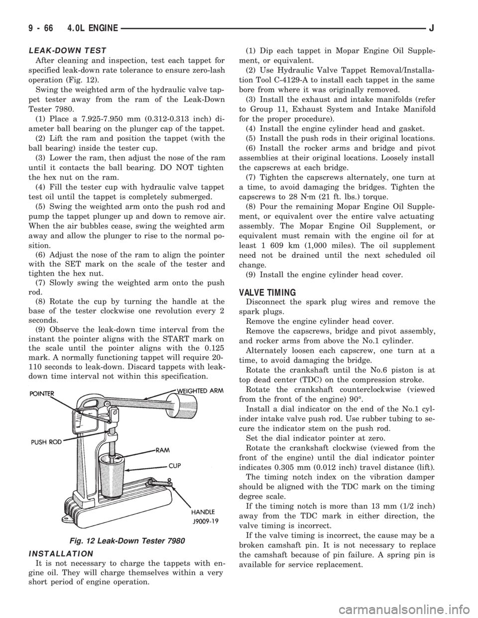
LEAK-DOWN TEST
After cleaning and inspection, test each tappet for
specified leak-down rate tolerance to ensure zero-lash
operation (Fig. 12).
Swing the weighted arm of the hydraulic valve tap-
pet tester away from the ram of the Leak-Down
Tester 7980.
(1) Place a 7.925-7.950 mm (0.312-0.313 inch) di-
ameter ball bearing on the plunger cap of the tappet.
(2) Lift the ram and position the tappet (with the
ball bearing) inside the tester cup.
(3) Lower the ram, then adjust the nose of the ram
until it contacts the ball bearing. DO NOT tighten
the hex nut on the ram.
(4) Fill the tester cup with hydraulic valve tappet
test oil until the tappet is completely submerged.
(5) Swing the weighted arm onto the push rod and
pump the tappet plunger up and down to remove air.
When the air bubbles cease, swing the weighted arm
away and allow the plunger to rise to the normal po-
sition.
(6) Adjust the nose of the ram to align the pointer
with the SET mark on the scale of the tester and
tighten the hex nut.
(7) Slowly swing the weighted arm onto the push
rod.
(8) Rotate the cup by turning the handle at the
base of the tester clockwise one revolution every 2
seconds.
(9) Observe the leak-down time interval from the
instant the pointer aligns with the START mark on
the scale until the pointer aligns with the 0.125
mark. A normally functioning tappet will require 20-
110 seconds to leak-down. Discard tappets with leak-
down time interval not within this specification.
INSTALLATION
It is not necessary to charge the tappets with en-
gine oil. They will charge themselves within a very
short period of engine operation.(1) Dip each tappet in Mopar Engine Oil Supple-
ment, or equivalent.
(2) Use Hydraulic Valve Tappet Removal/Installa-
tion Tool C-4129-A to install each tappet in the same
bore from where it was originally removed.
(3) Install the exhaust and intake manifolds (refer
to Group 11, Exhaust System and Intake Manifold
for the proper procedure).
(4) Install the engine cylinder head and gasket.
(5) Install the push rods in their original locations.
(6) Install the rocker arms and bridge and pivot
assemblies at their original locations. Loosely install
the capscrews at each bridge.
(7) Tighten the capscrews alternately, one turn at
a time, to avoid damaging the bridges. Tighten the
capscrews to 28 Nzm (21 ft. lbs.) torque.
(8) Pour the remaining Mopar Engine Oil Supple-
ment, or equivalent over the entire valve actuating
assembly. The Mopar Engine Oil Supplement, or
equivalent must remain with the engine oil for at
least 1 609 km (1,000 miles). The oil supplement
need not be drained until the next scheduled oil
change.
(9) Install the engine cylinder head cover.
VALVE TIMING
Disconnect the spark plug wires and remove the
spark plugs.
Remove the engine cylinder head cover.
Remove the capscrews, bridge and pivot assembly,
and rocker arms from above the No.1 cylinder.
Alternately loosen each capscrew, one turn at a
time, to avoid damaging the bridge.
Rotate the crankshaft until the No.6 piston is at
top dead center (TDC) on the compression stroke.
Rotate the crankshaft counterclockwise (viewed
from the front of the engine) 90É.
Install a dial indicator on the end of the No.1 cyl-
inder intake valve push rod. Use rubber tubing to se-
cure the indicator stem on the push rod.
Set the dial indicator pointer at zero.
Rotate the crankshaft clockwise (viewed from the
front of the engine) until the dial indicator pointer
indicates 0.305 mm (0.012 inch) travel distance (lift).
The timing notch index on the vibration damper
should be aligned with the TDC mark on the timing
degree scale.
If the timing notch is more than 13 mm (1/2 inch)
away from the TDC mark in either direction, the
valve timing is incorrect.
If the valve timing is incorrect, the cause may be a
broken camshaft pin. It is not necessary to replace
the camshaft because of pin failure. A spring pin is
available for service replacement.
Fig. 12 Leak-Down Tester 7980
9 - 66 4.0L ENGINEJ
Page 925 of 1784
(8) Check crankshaft end play. Crankshaft end
play is controlled by the thrust bearing which is
flange and installed at the No.2 main bearing posi-
tion.
(a) Attach a magnetic base dial indicator to the
cylinder block at either the front or rear of the en-
gine.
(b) Position the dial indicator rod so that it is
parallel to the center line of the crankshaft.
(c) Pry the crankshaft forward, position the dial
indicator to zero.
(d) Pry the crankshaft forward and backward.
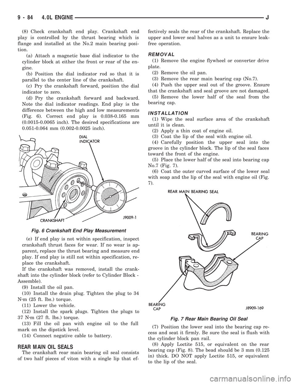
Note the dial indicator readings. End play is the
difference between the high and low measurements
(Fig. 6). Correct end play is 0.038-0.165 mm
(0.0015-0.0065 inch). The desired specifications are
0.051-0.064 mm (0.002-0.0025 inch).
(e) If end play is not within specification, inspect
crankshaft thrust faces for wear. If no wear is ap-
parent, replace the thrust bearing and measure end
play. If end play is still not within specification, re-
place the crankshaft.
If the crankshaft was removed, install the crank-
shaft into the cylinder block (refer to Cylinder Block -
Assemble).
(9) Install the oil pan.
(10) Install the drain plug. Tighten the plug to 34
Nzm (25 ft. lbs.) torque.
(11) Lower the vehicle.
(12) Install the spark plugs. Tighten the plugs to
37 Nzm (27 ft. lbs.) torque.
(13) Fill the oil pan with engine oil to the full
mark on the dipstick level.
(14) Connect negative cable to battery.
REAR MAIN OIL SEALS
The crankshaft rear main bearing oil seal consists
of two half pieces of viton with a single lip that ef-fectively seals the rear of the crankshaft. Replace the
upper and lower seal halves as a unit to ensure leak-
free operation.
REMOVAL
(1) Remove the engine flywheel or converter drive
plate.
(2) Remove the oil pan.
(3) Remove the rear main bearing cap (No.7).
(4) Push the upper seal out of the groove. Ensure
that the crankshaft and seal groove are not damaged.
(5) Remove the lower half of the seal from the
bearing cap.
INSTALLATION
(1) Wipe the seal surface area of the crankshaft
until it is clean.
(2) Apply a thin coat of engine oil.
(3) Coat the lip of the seal with engine oil.
(4) Carefully position the upper seal into the
groove in the cylinder block. The lip of the seal faces
toward the front of the engine.
(5) Place the lower half of the seal into bearing cap
No.7 (Fig. 7).
(6) Coat the outer curved surface of the lower seal
with soap and the lip of the seal with engine oil (Fig.
7).
(7) Position the lower seal into the bearing cap re-
cess and seat it firmly. Be sure the seal is flush with
the cylinder block pan rail.
(8) Apply Loctite 515, or equivalent on the rear
bearing cap (Fig. 8). The bead should be 3 mm (0.125
in) thick. DO NOT apply Loctite 515, or equivalent
to the lip of the seal.
Fig. 7 Rear Main Bearing Oil Seal
Fig. 6 Crankshaft End Play Measurement
9 - 84 4.0L ENGINEJ
Page 1761 of 1784
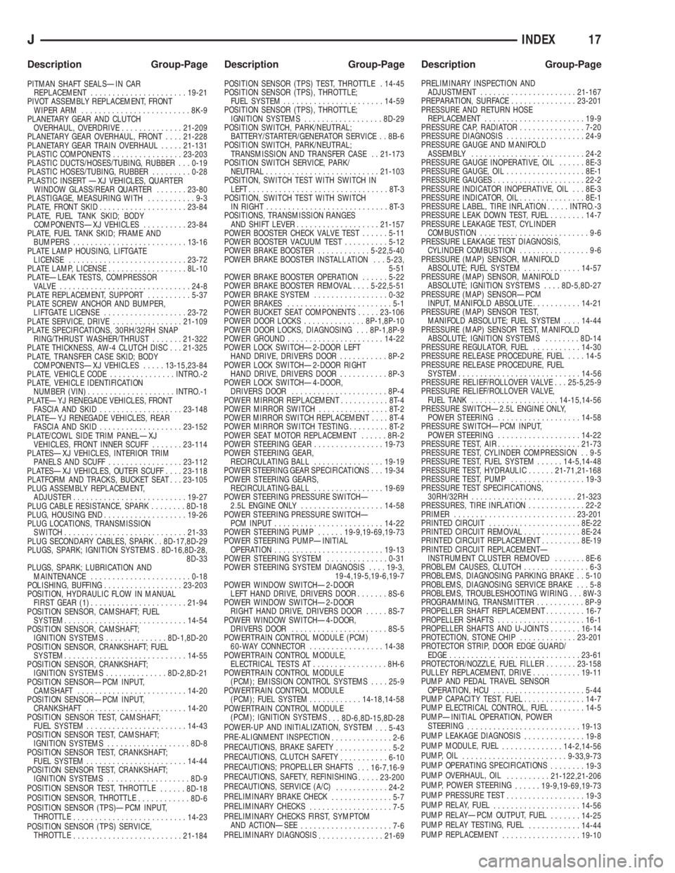
PITMAN SHAFT SEALSÐIN CAR
REPLACEMENT......................19-21
PIVOT ASSEMBLY REPLACEMENT, FRONT
WIPER ARM.........................8K-9
PLANETARY GEAR AND CLUTCH
OVERHAUL, OVERDRIVE..............21-209
PLANETARY GEAR OVERHAUL, FRONT....21-228
PLANETARY GEAR TRAIN OVERHAUL.....21-131
PLASTIC COMPONENTS................23-203
PLASTIC DUCTS/HOSES/TUBING, RUBBER . . . 0-19
PLASTIC HOSES/TUBING, RUBBER.........0-28
PLASTIC INSERT ÐXJ VEHICLES, QUARTER
WINDOW GLASS/REAR QUARTER.......23-80
PLASTIGAGE, MEASURING WITH...........9-3
PLATE, FRONT SKID....................23-84
PLATE, FUEL TANK SKID; BODY
COMPONENTSÐXJ VEHICLES..........23-84
PLATE, FUEL TANK SKID; FRAME AND
BUMPERS..........................13-16
PLATE LAMP HOUSING, LIFTGATE
LICENSE...........................23-72
PLATE LAMP, LICENSE..................8L-10
PLATEÐLEAK TESTS, COMPRESSOR
VALVE ..............................24-8
PLATE REPLACEMENT, SUPPORT..........5-37
PLATE SCREW ANCHOR AND BUMPER,
LIFTGATE LICENSE...................23-72
PLATE SERVICE, DRIVE................21-109
PLATE SPECIFICATIONS, 30RH/32RH SNAP
RING/THRUST WASHER/THRUST.......21-322
PLATE THICKNESS, AW-4 CLUTCH DISC . . . 21-325
PLATE, TRANSFER CASE SKID; BODY
COMPONENTSÐXJ VEHICLES.....13-15,23-84
PLATE, VEHICLE CODE...............INTRO.-2
PLATE, VEHICLE IDENTIFICATION
NUMBER (VIN)....................INTRO.-1
PLATEÐYJ RENEGADE VEHICLES, FRONT
FASCIA AND SKID...................23-148
PLATEÐYJ RENEGADE VEHICLES, REAR
FASCIA AND SKID...................23-152
PLATE/COWL SIDE TRIM PANELÐXJ
VEHICLES, FRONT INNER SCUFF.......23-114
PLATESÐXJ VEHICLES, INTERIOR TRIM
PANELS AND SCUFF.................23-112
PLATESÐXJ VEHICLES, OUTER SCUFF....23-118
PLATFORM AND TRACKS, BUCKET SEAT . . . 23-105
PLUG ASSEMBLY REPLACEMENT,
ADJUSTER..........................19-27
PLUG CABLE RESISTANCE, SPARK........8D-18
PLUG, HOUSING END...................19-26
PLUG LOCATIONS, TRANSMISSION
SWITCH............................21-33
PLUG SECONDARY CABLES, SPARK . . 8D-17,8D-29
PLUGS, SPARK; IGNITION SYSTEMS . 8D-16,8D-28,
8D-33
PLUGS, SPARK; LUBRICATION AND
MAINTENANCE.......................0-18
POLISHING, BUFFING..................23-203
POSITION, HYDRAULIC FLOW IN MANUAL
FIRST GEAR (1)......................21-94
POSITION SENSOR, CAMSHAFT; FUEL
SYSTEM............................14-54
POSITION SENSOR, CAMSHAFT;
IGNITION SYSTEMS..............8D-1,8D-20
POSITION SENSOR, CRANKSHAFT; FUEL
SYSTEM............................14-55
POSITION SENSOR, CRANKSHAFT;
IGNITION SYSTEMS..............8D-2,8D-21
POSITION SENSORÐPCM INPUT,
CAMSHAFT.........................14-20
POSITION SENSORÐPCM INPUT,
CRANKSHAFT.......................14-20
POSITION SENSOR TEST, CAMSHAFT;
FUEL SYSTEM.......................14-43
POSITION SENSOR TEST, CAMSHAFT;
IGNITION SYSTEMS...................8D-8
POSITION SENSOR TEST, CRANKSHAFT;
FUEL SYSTEM.......................14-44
POSITION SENSOR TEST, CRANKSHAFT;
IGNITION SYSTEMS...................8D-9
POSITION SENSOR TEST, THROTTLE
......8D-18
POSITION SENSOR, THROTTLE
............8D-6
POSITION SENSOR (TPS)ÐPCM INPUT,
THROTTLE
..........................14-23
POSITION SENSOR (TPS) SERVICE,
THROTTLE
.........................21-184POSITION SENSOR (TPS) TEST, THROTTLE . 14-45
POSITION SENSOR (TPS), THROTTLE;
FUEL SYSTEM.......................14-59
POSITION SENSOR (TPS), THROTTLE;
IGNITION SYSTEMS..................8D-29
POSITION SWITCH, PARK/NEUTRAL;
BATTERY/STARTER/GENERATOR SERVICE . . 8B-6
POSITION SWITCH, PARK/NEUTRAL;
TRANSMISSION AND TRANSFER CASE . . 21-173
POSITION SWITCH SERVICE, PARK/
NEUTRAL..........................21-103
POSITION, SWITCH TEST WITH SWITCH IN
LEFT................................8T-3
POSITION, SWITCH TEST WITH SWITCH
IN RIGHT............................8T-3
POSITIONS, TRANSMISSION RANGES
AND SHIFT LEVER...................21-157
POWER BOOSTER CHECK VALVE TEST......5-11
POWER BOOSTER VACUUM TEST..........5-12
POWER BRAKE BOOSTER............5-22,5-40
POWER BRAKE BOOSTER INSTALLATION . . . 5-23,
5-51
POWER BRAKE BOOSTER OPERATION......5-22
POWER BRAKE BOOSTER REMOVAL....5-22,5-51
POWER BRAKE SYSTEM.................0-32
POWER BRAKES........................5-1
POWER BUCKET SEAT COMPONENTS.....23-106
POWER DOOR LOCKS..............8P-1,8P-10
POWER DOOR LOCKS, DIAGNOSING . . . 8P-1,8P-9
POWER GROUND......................14-22
POWER LOCK SWITCHÐ2-DOOR LEFT
HAND DRIVE, DRIVERS DOOR...........8P-2
POWER LOCK SWITCHÐ2-DOOR RIGHT
HAND DRIVE, DRIVERS DOOR...........8P-3
POWER LOCK SWITCHÐ4-DOOR,
DRIVERS DOOR......................8P-4
POWER MIRROR REPLACEMENT...........8T-4
POWER MIRROR SWITCH................8T-2
POWER MIRROR SWITCH REPLACEMENT....8T-4
POWER MIRROR SWITCH TESTING.........8T-2
POWER SEAT MOTOR REPLACEMENT......8R-2
POWER STEERING GEAR................19-73
POWER STEERING GEAR,
RECIRCULATING BALL................19-19
POWER STEERING GEAR SPECIFICATIONS . . . 19-34
POWER STEERING GEARS,
RECIRCULATING-BALL................19-69
POWER STEERING PRESSURE SWITCHÐ
2.5L ENGINE ONLY...................14-58
POWER STEERING PRESSURE SWITCHÐ
PCM INPUT.........................14-22
POWER STEERING PUMP......19-9,19-69,19-73
POWER STEERING PUMPÐINITIAL
OPERATION.........................19-13
POWER STEERING SYSTEM..............0-31
POWER STEERING SYSTEM DIAGNOSIS....19-3,
19-4,19-5,19-6,19-7
POWER WINDOW SWITCHÐ2-DOOR
LEFT HAND DRIVE, DRIVERS DOOR.......8S-6
POWER WINDOW SWITCHÐ2-DOOR
RIGHT HAND DRIVE, DRIVERS DOOR.....8S-7
POWER WINDOW SWITCHÐ4-DOOR,
DRIVERS DOOR......................8S-5
POWERTRAIN CONTROL MODULE (PCM)
60-WAY CONNECTOR.................14-38
POWERTRAIN CONTROL MODULE,
ELECTRICAL TESTS AT.................8H-6
POWERTRAIN CONTROL MODULE
(PCM); EMISSION CONTROL SYSTEMS....25-9
POWERTRAIN CONTROL MODULE
(PCM); FUEL SYSTEM............14-18,14-58
POWERTRAIN CONTROL MODULE
(PCM); IGNITION SYSTEMS
. . . 8D-6,8D-15,8D-28
POWER-UP AND INITIALIZATION, SYSTEM
. . . 5-43
PRE-ALIGNMENT INSPECTION
..............2-6
PRECAUTIONS, BRAKE SAFETY
.............5-2
PRECAUTIONS, CLUTCH SAFETY
...........6-10
PRECAUTIONS; PROPELLER SHAFTS
. . . 16-7,16-9
PRECAUTIONS, SAFETY, REFINISHING
.....23-200
PRECAUTIONS, SERVICE (A/C)
............24-2
PRELIMINARY BRAKE CHECK
..............5-7
PRELIMINARY CHECKS
...................7-5
PRELIMINARY CHECKS FIRST, SYMPTOM
AND ACTIONÐSEE
.....................7-6
PRELIMINARY DIAGNOSIS
...............21-69PRELIMINARY INSPECTION AND
ADJUSTMENT......................21-167
PREPARATION, SURFACE...............23-201
PRESSURE AND RETURN HOSE
REPLACEMENT.......................19-9
PRESSURE CAP, RADIATOR...............7-20
PRESSURE DIAGNOSIS..................24-9
PRESSURE GAUGE AND MANIFOLD
ASSEMBLY..........................24-2
PRESSURE GAUGE INOPERATIVE, OIL......8E-3
PRESSURE GAUGE, OIL..................8E-1
PRESSURE GAUGES.....................22-2
PRESSURE INDICATOR INOPERATIVE, OIL . . . 8E-3
PRESSURE INDICATOR, OIL...............8E-1
PRESSURE LABEL, TIRE INFLATION.....INTRO.-3
PRESSURE LEAK DOWN TEST, FUEL........14-7
PRESSURE LEAKAGE TEST, CYLINDER
COMBUSTION.........................9-6
PRESSURE LEAKAGE TEST DIAGNOSIS,
CYLINDER COMBUSTION................9-6
PRESSURE (MAP) SENSOR, MANIFOLD
ABSOLUTE; FUEL SYSTEM.............14-57
PRESSURE (MAP) SENSOR, MANIFOLD
ABSOLUTE; IGNITION SYSTEMS....8D-5,8D-27
PRESSURE (MAP) SENSORÐPCM
INPUT, MANIFOLD ABSOLUTE...........14-21
PRESSURE (MAP) SENSOR TEST,
MANIFOLD ABSOLUTE; FUEL SYSTEM....14-44
PRESSURE (MAP) SENSOR TEST, MANIFOLD
ABSOLUTE; IGNITION SYSTEMS........8D-14
PRESSURE REGULATOR, FUEL...........14-30
PRESSURE RELEASE PROCEDURE, FUEL....14-5
PRESSURE RELEASE PROCEDURE, FUEL
SYSTEM............................14-56
PRESSURE RELIEF/ROLLOVER VALVE . . . 25-5,25-9
PRESSURE RELIEF/ROLLOVER VALVE,
FUEL TANK....................14-15,14-56
PRESSURE SWITCHÐ2.5L ENGINE ONLY,
POWER STEERING...................14-58
PRESSURE SWITCHÐPCM INPUT,
POWER STEERING...................14-22
PRESSURE TEST, AIR...................21-73
PRESSURE TEST, CYLINDER COMPRESSION . . 9-5
PRESSURE TEST, FUEL SYSTEM......14-5,14-48
PRESSURE TEST, HYDRAULIC......21-71,21-168
PRESSURE TEST, PUMP.................19-3
PRESSURE TEST SPECIFICATIONS,
30RH/32RH........................21-323
PRESSURES, TIRE INFLATION.............22-2
PRIMER............................23-201
PRINTED CIRCUIT.....................8E-22
PRINTED CIRCUIT REMOVAL.............8E-24
PRINTED CIRCUIT REPLACEMENT.........8E-19
PRINTED CIRCUIT REPLACEMENTÐ
INSTRUMENT CLUSTER REMOVED.......8E-6
PROBLEM CAUSES, CLUTCH...............6-3
PROBLEMS, DIAGNOSING PARKING BRAKE . . 5-10
PROBLEMS, DIAGNOSING SERVICE BRAKE . . . 5-8
PROBLEMS, TROUBLESHOOTING WIRING . . . 8W-3
PROGRAMMING, TRANSMITTER...........8P-9
PROPELLER SHAFT REPLACEMENT.........16-7
PROPELLER SHAFTS....................16-1
PROPELLER SHAFTS AND U-JOINTS.......16-14
PROTECTION, STONE CHIP.............23-201
PROTECTOR STRIP, DOOR EDGE GUARD/
EDGE..............................23-61
PROTECTOR/NOZZLE, FUEL FILLER.......23-158
PULLEY REPLACEMENT, DRIVE...........19-11
PUMP AND PEDAL TRAVEL SENSOR
OPERATION, HCU.....................5-44
PUMP CAPACITY TEST, FUEL..............14-7
PUMP ELECTRICAL CONTROL, FUEL........14-5
PUMPÐINITIAL OPERATION, POWER
STEERING
..........................19-13
PUMP LEAKAGE DIAGNOSIS
..............19-8
PUMP MODULE, FUEL
..............14-2,14-56
PUMP, OIL
........................9-33,9-73
PUMP OPERATING SPECIFICATIONS
........19-3
PUMP OVERHAUL, OIL
..........21-122,21-206
PUMP, POWER STEERING
......19-9,19-69,19-73
PUMP PRESSURE TEST
..................19-3
PUMP RELAY, FUEL
....................14-56
PUMP RELAYÐPCM OUTPUT, FUEL
.......14-25
PUMP RELAY TESTING, FUEL
............14-44
PUMP REPLACEMENT
..................19-10
JINDEX17
Description Group-Page Description Group-Page Description Group-Page
Page 1765 of 1784
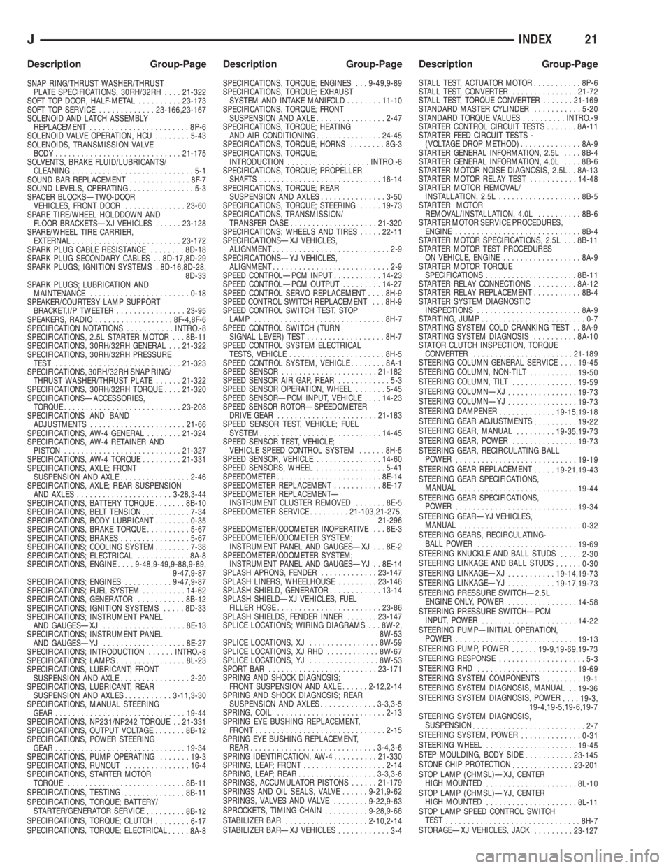
SNAP RING/THRUST WASHER/THRUST
PLATE SPECIFICATIONS, 30RH/32RH....21-322
SOFT TOP DOOR, HALF-METAL..........23-173
SOFT TOP SERVICE.............23-166,23-167
SOLENOID AND LATCH ASSEMBLY
REPLACEMENT.......................8P-6
SOLENOID VALVE OPERATION, HCU........5-43
SOLENOIDS, TRANSMISSION VALVE
BODY.............................21-175
SOLVENTS, BRAKE FLUID/LUBRICANTS/
CLEANING............................5-1
SOUND BAR REPLACEMENT..............8F-7
SOUND LEVELS, OPERATING...............5-3
SPACER BLOCKSÐTWO-DOOR
VEHICLES, FRONT DOOR..............23-60
SPARE TIRE/WHEEL HOLDDOWN AND
FLOOR BRACKETSÐXJ VEHICLES......23-128
SPARE/WHEEL TIRE CARRIER,
EXTERNAL.........................23-172
SPARK PLUG CABLE RESISTANCE........8D-18
SPARK PLUG SECONDARY CABLES . . 8D-17,8D-29
SPARK PLUGS; IGNITION SYSTEMS . 8D-16,8D-28,
8D-33
SPARK PLUGS; LUBRICATION AND
MAINTENANCE.......................0-18
SPEAKER/COURTESY LAMP SUPPORT
BRACKET,I/P TWEETER................23-95
SPEAKERS, RADIO..................8F-4,8F-6
SPECIFICATION NOTATIONS...........INTRO.-8
SPECIFICATIONS, 2.5L STARTER MOTOR . . . 8B-11
SPECIFICATIONS, 30RH/32RH GENERAL . . . 21-322
SPECIFICATIONS, 30RH/32RH PRESSURE
TEST.............................21-323
SPECIFICATIONS, 30RH/32RH SNAP RING/
THRUST WASHER/THRUST PLATE......21-322
SPECIFICATIONS, 30RH/32RH TORQUE....21-320
SPECIFICATIONSÐACCESSORIES,
TORQUE...........................23-208
SPECIFICATIONS AND BAND
ADJUSTMENTS......................21-66
SPECIFICATIONS, AW-4 GENERAL........21-324
SPECIFICATIONS, AW-4 RETAINER AND
PISTON...........................21-327
SPECIFICATIONS, AW-4 TORQUE.........21-331
SPECIFICATIONS, AXLE; FRONT
SUSPENSION AND AXLE................2-46
SPECIFICATIONS, AXLE; REAR SUSPENSION
AND AXLES......................3-28,3-44
SPECIFICATIONS, BATTERY TORQUE.......8B-10
SPECIFICATIONS, BELT TENSION...........7-34
SPECIFICATIONS, BODY LUBRICANT........0-35
SPECIFICATIONS, BRAKE TORQUE..........5-67
SPECIFICATIONS; BRAKES................5-67
SPECIFICATIONS; COOLING SYSTEM........7-38
SPECIFICATIONS; ELECTRICAL............8A-8
SPECIFICATIONS, ENGINE....9-48,9-49,9-88,9-89,
9-47,9-87
SPECIFICATIONS; ENGINES...........9-47,9-87
SPECIFICATIONS; FUEL SYSTEM..........14-62
SPECIFICATIONS, GENERATOR...........8B-12
SPECIFICATIONS; IGNITION SYSTEMS.....8D-33
SPECIFICATIONS; INSTRUMENT PANEL
AND GAUGESÐXJ...................8E-13
SPECIFICATIONS; INSTRUMENT PANEL
AND GAUGESÐYJ...................8E-27
SPECIFICATIONS; INTRODUCTION......INTRO.-8
SPECIFICATIONS; LAMPS................8L-23
SPECIFICATIONS, LUBRICANT; FRONT
SUSPENSION AND AXLE................2-20
SPECIFICATIONS, LUBRICANT; REAR
SUSPENSION AND AXLES...........3-11,3-30
SPECIFICATIONS, MANUAL STEERING
GEAR..............................19-44
SPECIFICATIONS, NP231/NP242 TORQUE . . 21-331
SPECIFICATIONS, OUTPUT VOLTAGE.......8B-12
SPECIFICATIONS, POWER STEERING
GEAR..............................19-34
SPECIFICATIONS, PUMP OPERATING.......19-3
SPECIFICATIONS, RUNOUT...............16-4
SPECIFICATIONS, STARTER MOTOR
TORQUE...........................8B-11
SPECIFICATIONS, TESTING
..............8B-11
SPECIFICATIONS, TORQUE; BATTERY/
STARTER/GENERATOR SERVICE
.........8B-12
SPECIFICATIONS, TORQUE; CLUTCH
........6-17
SPECIFICATIONS, TORQUE; ELECTRICAL
.....8A-8SPECIFICATIONS, TORQUE; ENGINES . . . 9-49,9-89
SPECIFICATIONS, TORQUE; EXHAUST
SYSTEM AND INTAKE MANIFOLD........11-10
SPECIFICATIONS, TORQUE; FRONT
SUSPENSION AND AXLE................2-47
SPECIFICATIONS, TORQUE; HEATING
AND AIR CONDITIONING...............24-45
SPECIFICATIONS, TORQUE; HORNS........8G-3
SPECIFICATIONS, TORQUE;
INTRODUCTION...................INTRO.-8
SPECIFICATIONS, TORQUE; PROPELLER
SHAFTS............................16-14
SPECIFICATIONS, TORQUE; REAR
SUSPENSION AND AXLES...............3-50
SPECIFICATIONS, TORQUE; STEERING.....19-73
SPECIFICATIONS, TRANSMISSION/
TRANSFER CASE....................21-320
SPECIFICATIONS; WHEELS AND TIRES.....22-11
SPECIFICATIONSÐXJ VEHICLES,
ALIGNMENT...........................2-9
SPECIFICATIONSÐYJ VEHICLES,
ALIGNMENT...........................2-9
SPEED CONTROLÐPCM INPUT...........14-23
SPEED CONTROLÐPCM OUTPUT.........14-27
SPEED CONTROL SERVO REPLACEMENT....8H-9
SPEED CONTROL SWITCH REPLACEMENT . . . 8H-9
SPEED CONTROL SWITCH TEST, STOP
LAMP..............................8H-7
SPEED CONTROL SWITCH (TURN
SIGNAL LEVER) TEST..................8H-7
SPEED CONTROL SYSTEM ELECTRICAL
TESTS, VEHICLE......................8H-5
SPEED CONTROL SYSTEM, VEHICLE........8A-1
SPEED SENSOR......................21-182
SPEED SENSOR AIR GAP, REAR............5-3
SPEED SENSOR OPERATION, WHEEL.......5-45
SPEED SENSORÐPCM INPUT, VEHICLE....14-23
SPEED SENSOR ROTORÐSPEEDOMETER
DRIVE GEAR.......................21-183
SPEED SENSOR TEST, VEHICLE; FUEL
SYSTEM............................14-45
SPEED SENSOR TEST, VEHICLE;
VEHICLE SPEED CONTROL SYSTEM......8H-5
SPEED SENSOR, VEHICLE...............14-60
SPEED SENSORS, WHEEL................5-41
SPEEDOMETER........................8E-14
SPEEDOMETER REPLACEMENT...........8E-17
SPEEDOMETER REPLACEMENTÐ
INSTRUMENT CLUSTER REMOVED.......8E-5
SPEEDOMETER SERVICE.........21-103,21-275,
21-296
SPEEDOMETER/ODOMETER INOPERATIVE . . . 8E-3
SPEEDOMETER/ODOMETER SYSTEM;
INSTRUMENT PANEL AND GAUGESÐXJ . . . 8E-2
SPEEDOMETER/ODOMETER SYSTEM;
INSTRUMENT PANEL AND GAUGESÐYJ . . 8E-14
SPLASH APRONS, FENDER.............23-147
SPLASH LINERS, WHEELHOUSE.........23-146
SPLASH SHIELD, GENERATOR............13-14
SPLASH SHIELDÐXJ VEHICLES, FUEL
FILLER HOSE........................23-86
SPLASH SHIELDS, FENDER INNER.......23-147
SPLICE LOCATIONS; WIRING DIAGRAMS . . . 8W-2,
8W-53
SPLICE LOCATIONS, XJ................8W-59
SPLICE LOCATIONS, XJ RHD............8W-67
SPLICE LOCATIONS, YJ................8W-53
SPORT BAR.........................23-171
SPRING AND SHOCK DIAGNOSIS;
FRONT SUSPENSION AND AXLE......2-12,2-14
SPRING AND SHOCK DIAGNOSIS; REAR
SUSPENSION AND AXLES.............3-3,3-5
SPRING, COIL.........................2-13
SPRING EYE BUSHING REPLACEMENT,
FRONT..............................2-15
SPRING EYE BUSHING REPLACEMENT,
REAR.............................3-4,3-6
SPRING IDENTIFICATION, AW-4..........21-330
SPRING, LEAF; FRONT...................2-14
SPRING, LEAF; REAR..................3-3,3-6
SPRINGS, ACCUMULATOR PISTONS......21-179
SPRINGS AND OIL SEALS, VALVE......9-21,9-62
SPRINGS, VALVES AND VALVE
........9-22,9-63
SPROCKETS, TIMING CHAIN
..........9-28,9-68
STABILIZER BAR
...................2-10,2-14
STABILIZER BARÐXJ VEHICLES
............3-4STALL TEST, ACTUATOR MOTOR...........8P-6
STALL TEST, CONVERTER...............21-72
STALL TEST, TORQUE CONVERTER.......21-169
STANDARD MASTER CYLINDER...........5-20
STANDARD TORQUE VALUES..........INTRO.-9
STARTER CONTROL CIRCUIT TESTS.......8A-11
STARTER FEED CIRCUIT TESTS -
(VOLTAGE DROP METHOD)..............8A-9
STARTER GENERAL INFORMATION, 2.5L....8B-4
STARTER GENERAL INFORMATION, 4.0L....8B-6
STARTER MOTOR NOISE DIAGNOSIS, 2.5L . . 8A-13
STARTER MOTOR RELAY TEST...........14-48
STARTER MOTOR REMOVAL/
INSTALLATION, 2.5L...................8B-5
STARTER MOTOR
REMOVAL/INSTALLATION, 4.0L..........8B-6
STARTER MOTOR SERVICE PROCEDURES,
ENGINE.............................8B-4
STARTER MOTOR SPECIFICATIONS, 2.5L . . . 8B-11
STARTER MOTOR TEST PROCEDURES
ON VEHICLE, ENGINE..................8A-9
STARTER MOTOR TORQUE
SPECIFICATIONS.....................8B-11
STARTER RELAY CONNECTIONS..........8A-12
STARTER RELAY REPLACEMENT...........8B-4
STARTER SYSTEM DIAGNOSTIC
INSPECTIONS........................8A-9
STARTING, JUMP........................0-7
STARTING SYSTEM COLD CRANKING TEST . . 8A-9
STARTING SYSTEM DIAGNOSIS..........8A-10
STATOR CLUTCH INSPECTION, TORQUE
CONVERTER.......................21-189
STEERING COLUMN GENERAL SERVICE....19-45
STEERING COLUMN, NON-TILT
...........19-50
STEERING COLUMN, TILT
...............19-59
STEERING COLUMNÐXJ
................19-73
STEERING COLUMNÐYJ
................19-73
STEERING DAMPENER
.............19-15,19-18
STEERING GEAR ADJUSTMENTS
..........19-22
STEERING GEAR, MANUAL
.........19-35,19-73
STEERING GEAR, POWER
...............19-73
STEERING GEAR, RECIRCULATING BALL
POWER
............................19-19
STEERING GEAR REPLACEMENT
.....19-21,19-43
STEERING GEAR SPECIFICATIONS,
MANUAL
...........................19-44
STEERING GEAR SPECIFICATIONS,
POWER
............................19-34
STEERING GEARÐYJ VEHICLES,
MANUAL
............................0-32
STEERING GEARS, RECIRCULATING-
BALL POWER
.......................19-69
STEERING KNUCKLE AND BALL STUDS
.....2-30
STEERING LINKAGE AND BALL STUDS
......0-30
STEERING LINKAGEÐXJ
...........19-14,19-73
STEERING LINKAGEÐYJ
...........19-17,19-73
STEERING PRESSURE SWITCHÐ2.5L
ENGINE ONLY, POWER
................14-58
STEERING PRESSURE SWITCHÐPCM
INPUT, POWER
......................14-22
STEERING PUMPÐINITIAL OPERATION,
POWER
............................19-13
STEERING PUMP, POWER
......19-9,19-69,19-73
STEERING RESPONSE
....................5-3
STEERING RHD
.......................19-69
STEERING SYSTEM COMPONENTS
.........19-1
STEERING SYSTEM DIAGNOSIS, MANUAL
. . 19-36
STEERING SYSTEM DIAGNOSIS, POWER
....19-3,
19-4,19-5,19-6,19-7
STEERING SYSTEM DIAGNOSIS,
SUSPENSION
..........................2-7
STEERING SYSTEM, POWER
..............0-31
STEERING WHEEL
.....................19-45
STEP MOULDING, BODY SIDE
...........23-145
STONE CHIP PROTECTION
..............23-201
STOP LAMP (CHMSL)ÐXJ, CENTER
HIGH MOUNTED
.....................8L-10
STOP LAMP (CHMSL)ÐYJ, CENTER
HIGH MOUNTED
.....................8L-11
STOP LAMP SPEED CONTROL SWITCH
TEST
...............................8H-7
STORAGEÐXJ VEHICLES, JACK
.........23-127
JINDEX21
Description Group-Page Description Group-Page Description Group-Page