brake JEEP CHEROKEE 1994 Service Service Manual
[x] Cancel search | Manufacturer: JEEP, Model Year: 1994, Model line: CHEROKEE, Model: JEEP CHEROKEE 1994Pages: 1784, PDF Size: 77.09 MB
Page 162 of 1784
CAUTION: Do not allow the master cylinder reser-
voir to run dry while bleeding the brakes. Running
dry will allow air to re-enter the system making a
second bleeding operation necessary.
(6) Perform ``Bleed Brake'' procedure with DRB II
scan tool. Procedure is described in DRB II software
information and diagnostic manual.
(a) Connect DRB II scan tool to diagnostic con-
nector.
(b) Run Bleed Brake procedure as described in
tester manual.
(7) Repeat conventional bleeding procedure out-
lined in steps (1) through (8).
(8) Top off master cylinder fluid level if necessary.
(9) Verify proper brake operation.
BRAKELINES AND HOSES
Metal brakelines and rubber brake hoses should be
inspected periodically and replaced if damaged.
Rubber brake hoses should be replaced if cut,
cracked, swollen, or leaking. Rubber hoses must be
replaced. They are not repairable parts.
When installing new, or original brakelines andhoses, lubricate the fitting threads with brake fluid
before connection.
The steel brakelines should be checked every time
the vehicle is in for normal maintainence. This is im-
portant on high mileage vehicles. It is even more im-
portant when a vehicle is operated in areas where
salt is used regularly on the road surface during win-
ter.
Heavily rusted/corroded brake rotors, drums, sup-
port plates, and brakelines should be cleaned and
carefully inspected. Heavy rust buildup can hide se-
vere damge to a component. Severely rusted parts
should be replaced if you are unsure about their con-
dition.
COMBINATION VALVE
The combination valve is not a serviceable part.
The valve must be replaced if a malfunction occurs.
BRAKELINE CHARTS
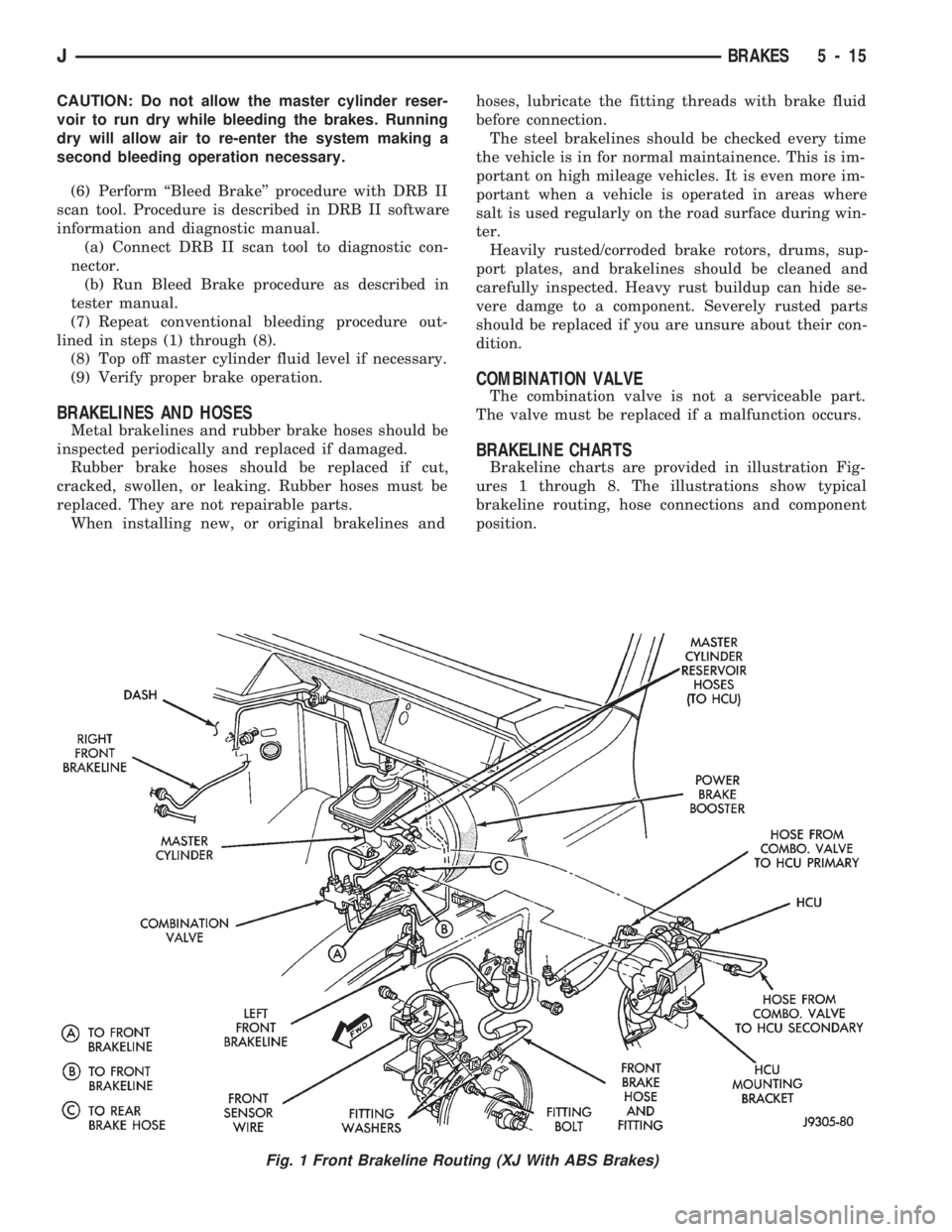
Brakeline charts are provided in illustration Fig-
ures 1 through 8. The illustrations show typical
brakeline routing, hose connections and component
position.
Fig. 1 Front Brakeline Routing (XJ With ABS Brakes)
JBRAKES 5 - 15
Page 163 of 1784
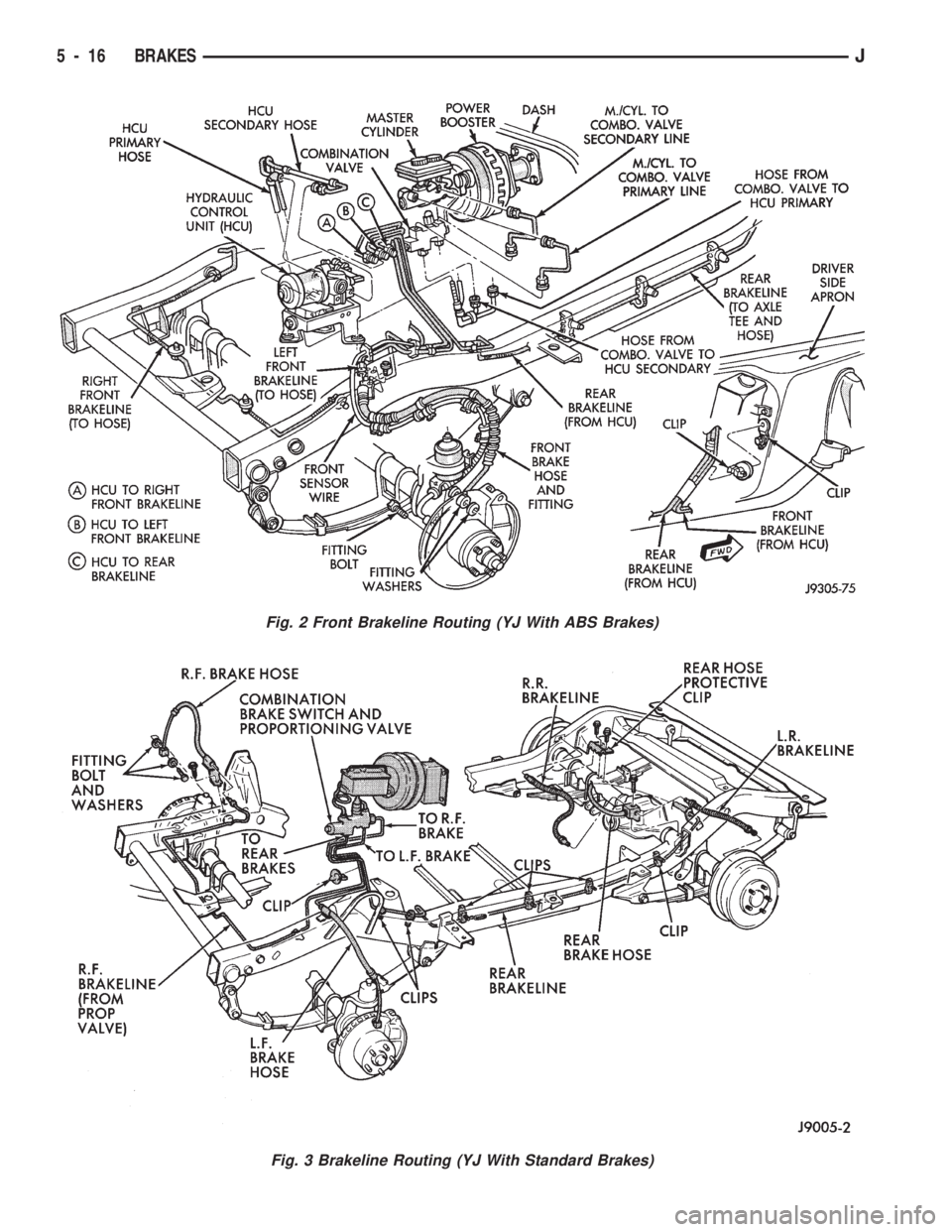
Fig. 2 Front Brakeline Routing (YJ With ABS Brakes)
Fig. 3 Brakeline Routing (YJ With Standard Brakes)
5 - 16 BRAKESJ
Page 164 of 1784
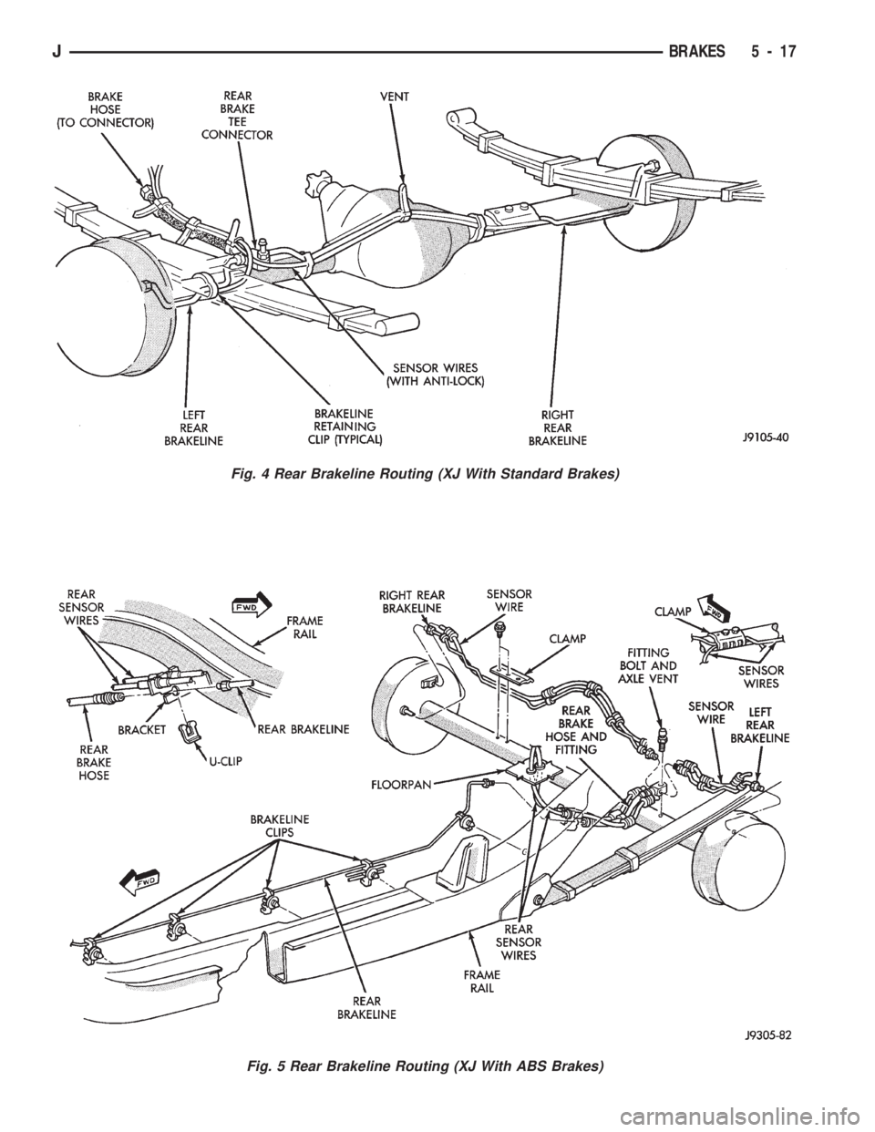
Fig. 4 Rear Brakeline Routing (XJ With Standard Brakes)
Fig. 5 Rear Brakeline Routing (XJ With ABS Brakes)
JBRAKES 5 - 17
Page 165 of 1784
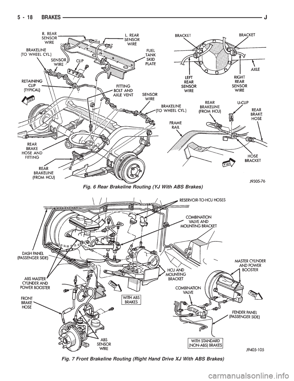
Fig. 6 Rear Brakeline Routing (YJ With ABS Brakes)
Fig. 7 Front Brakeline Routing (Right Hand Drive XJ With ABS Brakes)
5 - 18 BRAKESJ
Page 166 of 1784
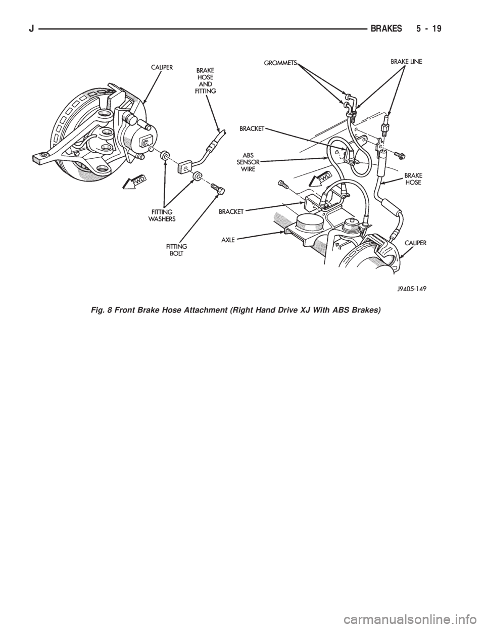
Fig. 8 Front Brake Hose Attachment (Right Hand Drive XJ With ABS Brakes)
JBRAKES 5 - 19
Page 167 of 1784
STANDARD MASTER CYLINDER
INDEX
page page
General Service Information................ 20
Master Cylinder Installation................. 20Master Cylinder Overhaul.................. 20
Master Cylinder Removal.................. 20
GENERAL SERVICE INFORMATION
The service information in this section covers the
standard (non-ABS) master cylinder only. The center
feed master cylinder used with the ABS system is
covered in the antilock brake component service sec-
tion.
MASTER CYLINDER REMOVAL
(1) Disconnect brake lines at master cylinder.
(2) Remove cylinder mounting nuts and remove
master cylinder.
(3) Remove cylinder cover and drain fluid.
MASTER CYLINDER INSTALLATION
(1) Bleed master cylinder on bench before installa-
tion. Refer to overhaul assembly procedure in this
section for bleeding method.
(2) Install cylinder on brake booster studs and in-
stall cylinder attaching nuts. Tighten nuts to 21 NIm
(15 ft. lbs.).
(3) Connect brakelines to cylinder.
(4) Fill and bleed brake system.
MASTER CYLINDER OVERHAUL
CYLINDER DISASSEMBLY
(1) Remove cylinder cover and drain fluid.
(2) Examine cylinder cover seal. Discard seal if
torn or distorted.
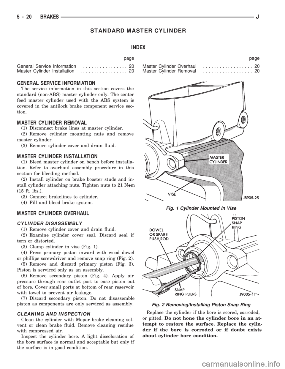
(3) Clamp cylinder in vise (Fig. 1).
(4) Press primary piston inward with wood dowel
or phillips screwdriver and remove snap ring (Fig. 2).
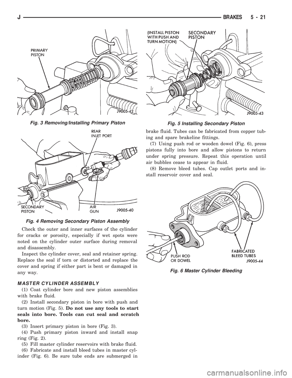
(5) Remove and discard primary piston (Fig. 3).
Piston is serviced only as an assembly.
(6) Remove secondary piston (Fig. 4). Apply air
pressure through rear outlet port to ease piston out
of bore. Cover small ports at bottom of rear reservoir
with towel to prevent air leakage.
(7) Discard secondary piston. Do not disassemble
piston as components are only serviced as assembly.
CLEANING AND INSPECTION
Clean the cylinder with Mopar brake cleaning sol-
vent or clean brake fluid. Remove cleaning residue
with compressed air.
Inspect the cylinder bore. A light discoloration of
the bore surface is normal and acceptable but only if
the surface is in good condition.Replace the cylinder if the bore is scored, corroded,
or pitted.Do not hone the cylinder bore in an at-
tempt to restore the surface. Replace the cylin-
der if the bore is corroded or if doubt exists
about cylinder bore condition.
Fig. 1 Cylinder Mounted In Vise
Fig. 2 Removing/Installing Piston Snap Ring
5 - 20 BRAKESJ
Page 168 of 1784
Check the outer and inner surfaces of the cylinder
for cracks or porosity, especially if wet spots were
noted on the cylinder outer surface during removal
and disassembly.
Inspect the cylinder cover, seal and retainer spring.
Replace the seal if torn or distorted and replace the
cover and spring if either part is bent or damaged in
any way.
MASTER CYLINDER ASSEMBLY
(1) Coat cylinder bore and new piston assemblies
with brake fluid.
(2) Install secondary piston in bore with push and
turn motion (Fig. 5).Do not use any tools to start
seals into bore. Tools can cut seal and scratch
bore.
(3) Insert primary piston in bore (Fig. 3).
(4) Push primary piston inward and install snap
ring (Fig. 2).
(5) Fill master cylinder reservoirs with brake fluid.
(6) Fabricate and install bleed tubes in master cyl-
inder (Fig. 6). Be sure tube ends are submerged inbrake fluid. Tubes can be fabricated from copper tub-
ing and spare brakeline fittings.
(7) Using push rod or wooden dowel (Fig. 6), press
pistons fully into bore and allow pistons to return
under spring pressure. Repeat this operation until
air bubbles cease to appear in fluid.
(8) Remove bleed tubes. Cap outlet ports and in-
stall reservoir cover and seal.
Fig. 5 Installing Secondary PistonFig. 3 Removing/Installing Primary Piston
Fig. 4 Removing Secondary Piston Assembly
Fig. 6 Master Cylinder Bleeding
JBRAKES 5 - 21
Page 169 of 1784
POWER BRAKE BOOSTER
INDEX
page page
Power Brake Booster Installation............. 23
Power Brake Booster Operation............. 22Power Brake Booster Removal.............. 22
Service Information....................... 22
SERVICE INFORMATION
The power brake booster is not a serviceable com-
ponent. If a booster malfunction occurs, the booster
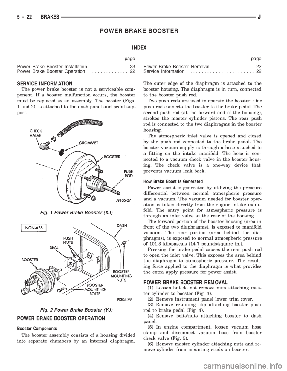
must be replaced as an assembly. The booster (Figs.
1 and 2), is attached to the dash panel and pedal sup-
port.
POWER BRAKE BOOSTER OPERATION
Booster Components
The booster assembly consists of a housing divided
into separate chambers by an internal diaphragm.The outer edge of the diaphragm is attached to the
booster housing. The diaphragm is in turn, connected
to the booster push rod.
Two push rods are used to operate the booster. One
push rod connects the booster to the brake pedal. The
second push rod (at the forward end of the housing),
strokes the master cylinder pistons. The rear push
rod is connected to the two diaphragms in the booster
housing.
The atmospheric inlet valve is opened and closed
by the push rod connected to the brake pedal. The
booster vacuum supply is through a hose attached to
a fitting on the intake manifold. The hose is con-
nected to a vacuum check valve in the booster hous-
ing. The check valve is a one-way device that
prevents vacuum leak back.
How Brake Boost Is Generated
Power assist is generated by utilizing the pressure
differential between normal atmospheric pressure
and a vacuum. The vacuum needed for booster oper-
ation is taken directly from the engine intake mani-
fold. The entry point for atmospheric pressure is
through an inlet valve at the rear of the housing.
The forward portion of the booster housing (area in
front of the two diaphragms), is exposed to manifold
vacuum. The rear portion (area behind the dia-
phragms), is exposed to normal atmospheric pressure
of 101.3 kilopascals (14.7 pounds/square in.).
Pressing the brake pedal causes the rear push rod
to open the inlet valve. This exposes the area behind
the diaphragm to atmospheric pressure. The result-
ing force applied to the diaphragm is what provides
the extra apply pressure for power assist.
POWER BRAKE BOOSTER REMOVAL
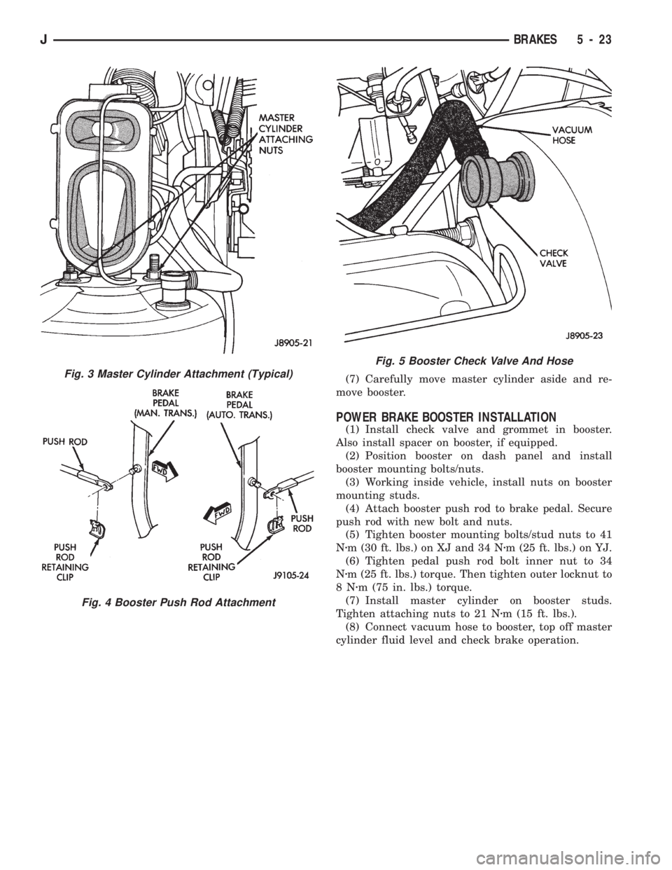
(1) Loosen but do not remove nuts attaching mas-
ter cylinder to booster (Fig. 3).
(2) Remove instrument panel lower trim cover.
(3) Remove retaining clip attaching booster push
rod to brake pedal (Fig. 4).
(4) Remove bolts/nuts attaching booster to dash
panel.
(5) In engine compartment, loosen vacuum hose
clamp and disconnect vacuum hose from booster
check valve (Fig. 5).
(6) Remove master cylinder attaching nuts and re-
move cylinder from mounting studs on booster.
Fig. 1 Power Brake Booster (XJ)
Fig. 2 Power Brake Booster (YJ)
5 - 22 BRAKESJ
Page 170 of 1784
(7) Carefully move master cylinder aside and re-
move booster.
POWER BRAKE BOOSTER INSTALLATION
(1) Install check valve and grommet in booster.
Also install spacer on booster, if equipped.
(2) Position booster on dash panel and install
booster mounting bolts/nuts.
(3) Working inside vehicle, install nuts on booster
mounting studs.
(4) Attach booster push rod to brake pedal. Secure
push rod with new bolt and nuts.
(5) Tighten booster mounting bolts/stud nuts to 41
Nzm (30 ft. lbs.) on XJ and 34 Nzm (25 ft. lbs.) on YJ.
(6) Tighten pedal push rod bolt inner nut to 34
Nzm (25 ft. lbs.) torque. Then tighten outer locknut to
8Nzm (75 in. lbs.) torque.
(7) Install master cylinder on booster studs.
Tighten attaching nuts to 21 Nzm (15 ft. lbs.).
(8) Connect vacuum hose to booster, top off master
cylinder fluid level and check brake operation.
Fig. 3 Master Cylinder Attachment (Typical)
Fig. 4 Booster Push Rod Attachment
Fig. 5 Booster Check Valve And Hose
JBRAKES 5 - 23
Page 171 of 1784
DISC BRAKES
INDEX
page page
Caliper Assembly........................ 29
Caliper Cleaning and Inspection............. 28
Caliper Disassembly...................... 27
Caliper Installation........................ 30
Caliper Operation and Wear Compensation..... 24
Caliper Removal......................... 27
Disc Brake Rotor Refinishing................ 32
Disc Brake Rotor Runout................... 31Disc Brake Rotor Thickness................ 31
Disc Brake Rotor Thickness Variation......... 31
Disc Brakeshoe Installation................. 26
Disc Brakeshoe Removal.................. 25
General Information....................... 24
Rotor Installation......................... 30
Rotor Removal.......................... 30
Wheel Nut Tightening..................... 32
GENERAL INFORMATION
1994 Jeep XJ/YJ models are equipped with single
piston, floating-type disc brake calipers. Ventilated,
cast rotors are used for all applications.
The disc brake calipers are supported in mounting
arms that are an integral part of the steering
knuckle. The calipers slide on mounting bolts that
also attach the calipers to the steering knuckle.
CALIPER OPERATION AND WEAR COMPENSATION
Caliper Operation
The significant feature of single piston caliper op-
eration is that the calipers are free to slide laterally
on the mounting bolts. It is the freedom of lateral
movement that allows continous compensation for
lining wear.
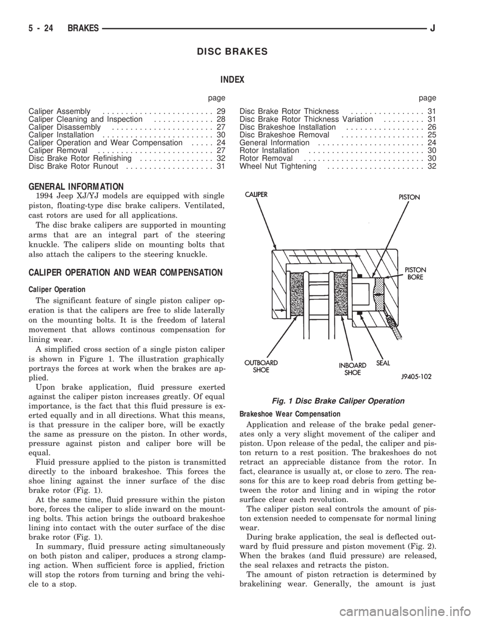
A simplified cross section of a single piston caliper
is shown in Figure 1. The illustration graphically
portrays the forces at work when the brakes are ap-
plied.
Upon brake application, fluid pressure exerted
against the caliper piston increases greatly. Of equal
importance, is the fact that this fluid pressure is ex-
erted equally and in all directions. What this means,
is that pressure in the caliper bore, will be exactly
the same as pressure on the piston. In other words,
pressure against piston and caliper bore will be
equal.
Fluid pressure applied to the piston is transmitted
directly to the inboard brakeshoe. This forces the
shoe lining against the inner surface of the disc
brake rotor (Fig. 1).
At the same time, fluid pressure within the piston
bore, forces the caliper to slide inward on the mount-
ing bolts. This action brings the outboard brakeshoe
lining into contact with the outer surface of the disc
brake rotor (Fig. 1).
In summary, fluid pressure acting simultaneously
on both piston and caliper, produces a strong clamp-
ing action. When sufficient force is applied, friction
will stop the rotors from turning and bring the vehi-
cle to a stop.Brakeshoe Wear Compensation
Application and release of the brake pedal gener-
ates only a very slight movement of the caliper and
piston. Upon release of the pedal, the caliper and pis-
ton return to a rest position. The brakeshoes do not
retract an appreciable distance from the rotor. In
fact, clearance is usually at, or close to zero. The rea-
sons for this are to keep road debris from getting be-
tween the rotor and lining and in wiping the rotor
surface clear each revolution.
The caliper piston seal controls the amount of pis-
ton extension needed to compensate for normal lining
wear.
During brake application, the seal is deflected out-
ward by fluid pressure and piston movement (Fig. 2).
When the brakes (and fluid pressure) are released,
the seal relaxes and retracts the piston.
The amount of piston retraction is determined by
brakelining wear. Generally, the amount is just
Fig. 1 Disc Brake Caliper Operation
5 - 24 BRAKESJ