JEEP CHEROKEE 1994 Service Manual PDF
Manufacturer: JEEP, Model Year: 1994, Model line: CHEROKEE, Model: JEEP CHEROKEE 1994Pages: 1784, PDF Size: 77.09 MB
Page 61 of 1784
CAUTION: Never loosen the pinion gear nut to de-
crease the pinion gear bearing preload torque. If the
specified preload torque is exceeded, a new col-
lapsible spacer must be installed. The torque se-
quence will have to be repeated.
(4) Install a socket and inch-pound torque wrench
on the pinion nut.
(5) Rotate the shaft with the torque wrench and
note the torque.
Required preload torque is the amount re-
corded during removal plus an additional 0.56
Nzm (5 in. lbs.).
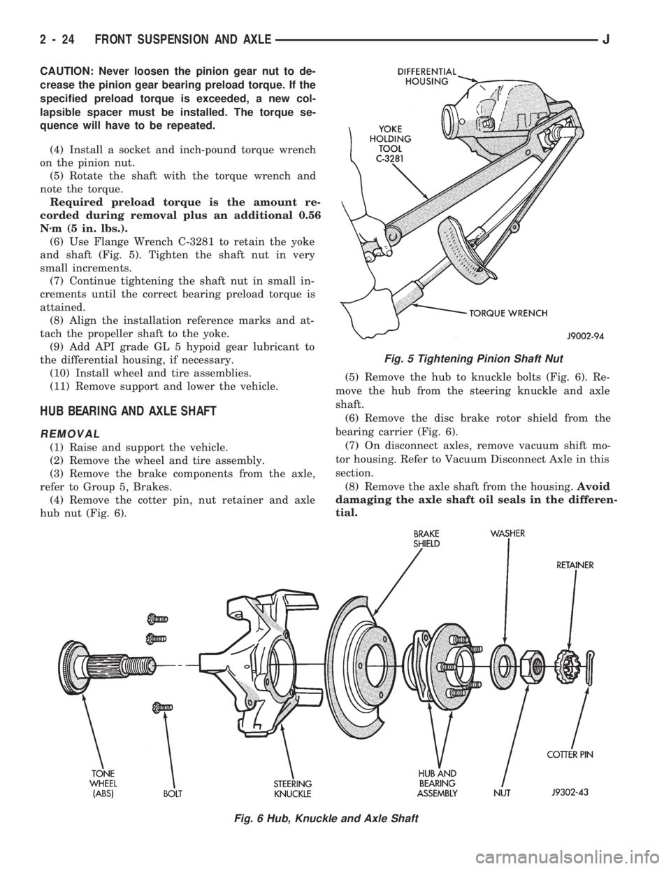
(6) Use Flange Wrench C-3281 to retain the yoke
and shaft (Fig. 5). Tighten the shaft nut in very
small increments.
(7) Continue tightening the shaft nut in small in-
crements until the correct bearing preload torque is
attained.
(8) Align the installation reference marks and at-
tach the propeller shaft to the yoke.
(9) Add API grade GL 5 hypoid gear lubricant to
the differential housing, if necessary.
(10) Install wheel and tire assemblies.
(11) Remove support and lower the vehicle.
HUB BEARING AND AXLE SHAFT
REMOVAL
(1) Raise and support the vehicle.
(2) Remove the wheel and tire assembly.
(3) Remove the brake components from the axle,
refer to Group 5, Brakes.
(4) Remove the cotter pin, nut retainer and axle
hub nut (Fig. 6).(5) Remove the hub to knuckle bolts (Fig. 6). Re-
move the hub from the steering knuckle and axle
shaft.
(6) Remove the disc brake rotor shield from the
bearing carrier (Fig. 6).
(7) On disconnect axles, remove vacuum shift mo-
tor housing. Refer to Vacuum Disconnect Axle in this
section.
(8) Remove the axle shaft from the housing.Avoid
damaging the axle shaft oil seals in the differen-
tial.
Fig. 5 Tightening Pinion Shaft Nut
Fig. 6 Hub, Knuckle and Axle Shaft
2 - 24 FRONT SUSPENSION AND AXLEJ
Page 62 of 1784
INSTALLATION
(1) Thoroughly clean the axle shaft (Fig. 6) and ap-
ply a thin film of Mopar Wheel Bearing Grease to
the shaft splines, seal contact surface, hub bore.
(2) Install the axle shaft into the housing and dif-
ferential side gears. Avoid damaging the axle shaft
oil seals in the differential.
(3) Install the hub bearing and brake dust shield
to the knuckle.
(4) Install the hub to knuckle bolts and tighten to
102 Nzm (75 ft. lbs.) torque.
(5) Install the hub washer and nut. Tighten the
hub nut to 237 Nzm (175 ft. lbs.) torque. Install the
nut retainer and a new cotter pin (Fig. 6).
(6) Install the brake components, refer to Group 5,
Brakes.
(7) Install the wheel and tire assembly.
(8) Remove support and lower the vehicle.
AXLE SHAFTÐ CARDAN U-JOINT
DISASSEMBLY
Single cardan U-joints are not serviceable. If defec-
tive, they must be replaced as a unit. If the bearings,
seals, spider or bearing caps are damaged or worn,
replace the complete U-joint.
CAUTION: Clamp only the forged portion of the
yoke in the vise. Also, to avoid distorting the yoke,
do not over tighten the vise jaws.
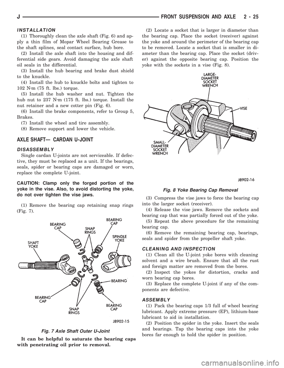
(1) Remove the bearing cap retaining snap rings
(Fig. 7).
It can be helpful to saturate the bearing caps
with penetrating oil prior to removal.(2) Locate a socket that is larger in diameter than
the bearing cap. Place the socket (receiver) against
the yoke and around the perimeter of the bearing cap
to be removed. Locate a socket that is smaller in di-
ameter than the bearing cap. Place the socket (driv-
er) against the opposite bearing cap. Position the
yoke with the sockets in a vise (Fig. 8).
(3) Compress the vise jaws to force the bearing cap
into the larger socket (receiver).
(4) Release the vise jaws. Remove the sockets and
bearing cap that was partially forced out of the yoke.
(5) Repeat the above procedure for the remaining
bearing cap.
(6) Remove the remaining bearing cap, bearings,
seals and spider from the propeller shaft yoke.
CLEANING AND INSPECTION
(1) Clean all the U-joint yoke bores with cleaning
solvent and a wire brush. Ensure that all the rust
and foreign matter are removed from the bores.
(2) Inspect the yokes for distortion, cracks and
worn bearing cap bores.
(3) Replace the complete U-joint if any of the com-
ponents are defective.
ASSEMBLY
(1) Pack the bearing caps 1/3 full of wheel bearing
lubricant. Apply extreme pressure (EP), lithium-base
lubricant to aid in installation.
(2) Position the spider in the yoke. Insert the seals
and bearings. Tap the bearing caps into the yoke
bores far enough to hold the spider in position.
Fig. 7 Axle Shaft Outer U-Joint
Fig. 8 Yoke Bearing Cap Removal
JFRONT SUSPENSION AND AXLE 2 - 25
Page 63 of 1784
(3) Place the socket (driver) against one bearing
cap. Position the yoke with the socket wrench in a
vise.
(4) Compress the vise to force the bearing caps into
the yoke. Force the caps enough to install the retain-
ing clips.
(5) Install the bearing cap retaining clips.
(6) Install the axle shaft, refer to Hub Bearing and
Axle Shaft installation.
VACUUM DISCONNECT AXLE Ð YJ VEHICLES
VACUUM CONTROL SYSTEM
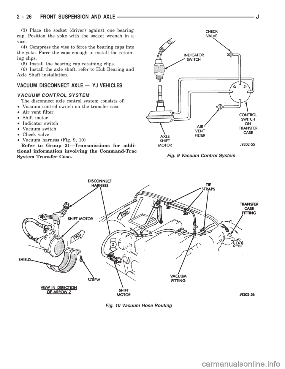
The disconnect axle control system consists of;
²Vacuum control switch on the transfer case
²Air vent filter
²Shift motor
²Indicator switch
²Vacuum switch
²Check valve
²Vacuum harness (Fig. 9, 10)
Refer to Group 21ÐTransmissions for addi-
tional information involving the Command-Trac
System Transfer Case.
Fig. 9 Vacuum Control System
Fig. 10 Vacuum Hose Routing
2 - 26 FRONT SUSPENSION AND AXLEJ
Page 64 of 1784
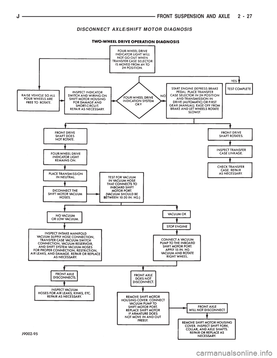
DISCONNECT AXLE/SHIFT MOTOR DIAGNOSIS
JFRONT SUSPENSION AND AXLE 2 - 27
Page 65 of 1784
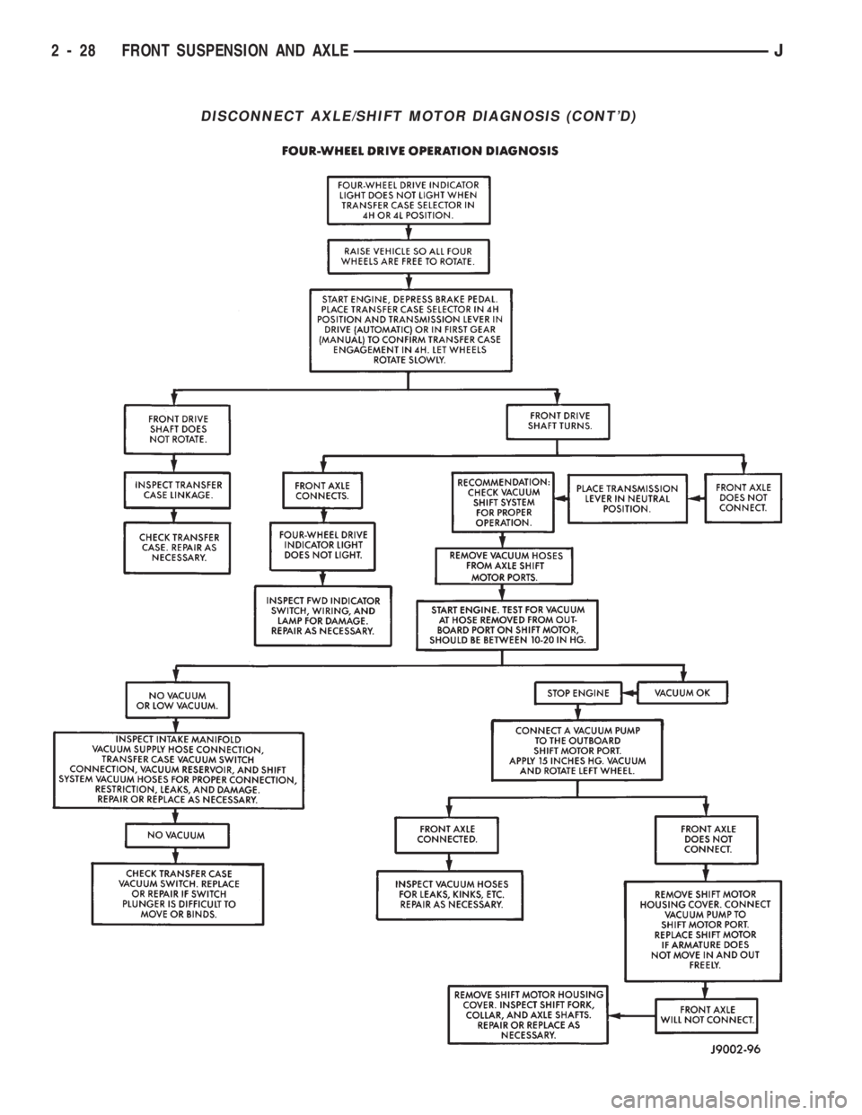
DISCONNECT AXLE/SHIFT MOTOR DIAGNOSIS (CONT'D)
2 - 28 FRONT SUSPENSION AND AXLEJ
Page 66 of 1784
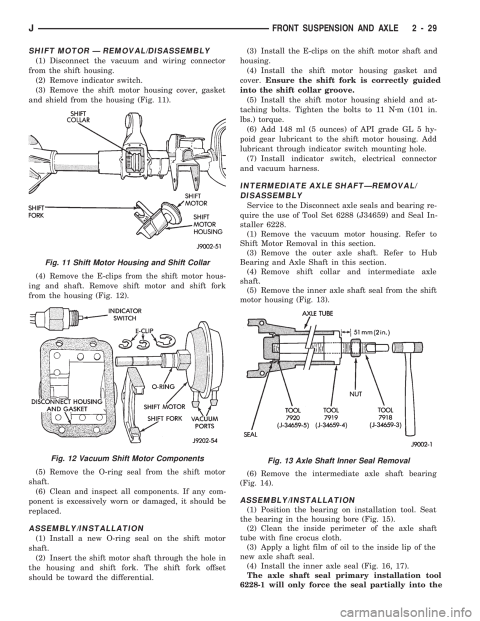
SHIFT MOTOR Ð REMOVAL/DISASSEMBLY
(1) Disconnect the vacuum and wiring connector
from the shift housing.
(2) Remove indicator switch.
(3) Remove the shift motor housing cover, gasket
and shield from the housing (Fig. 11).
(4) Remove the E-clips from the shift motor hous-
ing and shaft. Remove shift motor and shift fork
from the housing (Fig. 12).
(5) Remove the O-ring seal from the shift motor
shaft.
(6) Clean and inspect all components. If any com-
ponent is excessively worn or damaged, it should be
replaced.
ASSEMBLY/INSTALLATION
(1) Install a new O-ring seal on the shift motor
shaft.
(2) Insert the shift motor shaft through the hole in
the housing and shift fork. The shift fork offset
should be toward the differential.(3) Install the E-clips on the shift motor shaft and
housing.
(4) Install the shift motor housing gasket and
cover.Ensure the shift fork is correctly guided
into the shift collar groove.
(5) Install the shift motor housing shield and at-
taching bolts. Tighten the bolts to 11 Nzm (101 in.
lbs.) torque.
(6) Add 148 ml (5 ounces) of API grade GL 5 hy-
poid gear lubricant to the shift motor housing. Add
lubricant through indicator switch mounting hole.
(7) Install indicator switch, electrical connector
and vacuum harness.
INTERMEDIATE AXLE SHAFTÐREMOVAL/
DISASSEMBLY
Service to the Disconnect axle seals and bearing re-
quire the use of Tool Set 6288 (J34659) and Seal In-
staller 6228.
(1) Remove the vacuum motor housing. Refer to
Shift Motor Removal in this section.
(3) Remove the outer axle shaft. Refer to Hub
Bearing and Axle Shaft in this section.
(4) Remove shift collar and intermediate axle
shaft.
(5) Remove the inner axle shaft seal from the shift
motor housing (Fig. 13).
(6) Remove the intermediate axle shaft bearing
(Fig. 14).
ASSEMBLY/INSTALLATION
(1) Position the bearing on installation tool. Seat
the bearing in the housing bore (Fig. 15).
(2) Clean the inside perimeter of the axle shaft
tube with fine crocus cloth.
(3) Apply a light film of oil to the inside lip of the
new axle shaft seal.
(4) Install the inner axle seal (Fig. 16, 17).
The axle shaft seal primary installation tool
6228-1 will only force the seal partially into the
Fig. 11 Shift Motor Housing and Shift Collar
Fig. 12 Vacuum Shift Motor ComponentsFig. 13 Axle Shaft Inner Seal Removal
JFRONT SUSPENSION AND AXLE 2 - 29
Page 67 of 1784
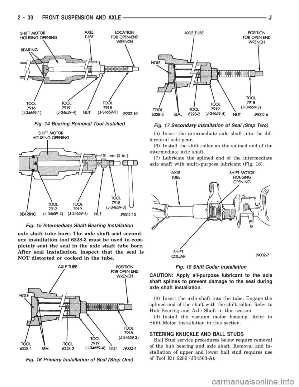
axle shaft tube bore. The axle shaft seal second-
ary installation tool 6228-3 must be used to com-
pletely seat the seal in the axle shaft tube bore.
After seal installation, inspect that the seal is
NOT distorted or cocked in the tube.(5) Insert the intermediate axle shaft into the dif-
ferential side gear.
(6) Install the shift collar on the splined end of the
intermediate axle shaft.
(7) Lubricate the splined end of the intermediate
axle shaft with multi-purpose lubricant (Fig. 18).
CAUTION: Apply all-purpose lubricant to the axle
shaft splines to prevent damage to the seal during
axle shaft installation.
(8) Insert the axle shaft into the tube. Engage the
splined-end of the shaft with the shift collar. Refer to
Hub Bearing and Axle Shaft in this section.
(9) Install the vacuum motor housing. Refer to
Shift Motor Installation in this section.
STEERING KNUCKLE AND BALL STUDS
Ball Stud service procedures below require removal
of the hub bearing and axle shaft. Removal and in-
stallation of upper and lower ball stud requires use
of Tool Kit 6289 (J34503-A).
Fig. 14 Bearing Removal Tool Installed
Fig. 15 Intermediate Shaft Bearing Installation
Fig. 16 Primary Installation of Seal (Step One)
Fig. 17 Secondary Installation of Seal (Step Two)
Fig. 18 Shift Collar Installation
2 - 30 FRONT SUSPENSION AND AXLEJ
Page 68 of 1784
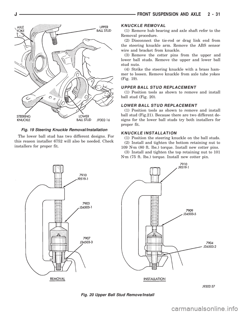
The lower ball stud has two different designs. For
this reason installer 6752 will also be needed. Check
installers for proper fit.
KNUCKLE REMOVAL
(1) Remove hub bearing and axle shaft refer to the
Removal procedure.
(2) Disconnect the tie-rod or drag link end from
the steering knuckle arm. Remove the ABS sensor
wire and bracket from knuckle.
(3) Remove the cotter pins from the upper and
lower ball studs. Remove the upper and lower ball
stud nuts.
(4) Strike the steering knuckle with a brass ham-
mer to loosen. Remove knuckle from axle tube yokes
(Fig. 19).
UPPER BALL STUD REPLACEMENT
(1) Position tools as shown to remove and install
ball stud (Fig. 20).
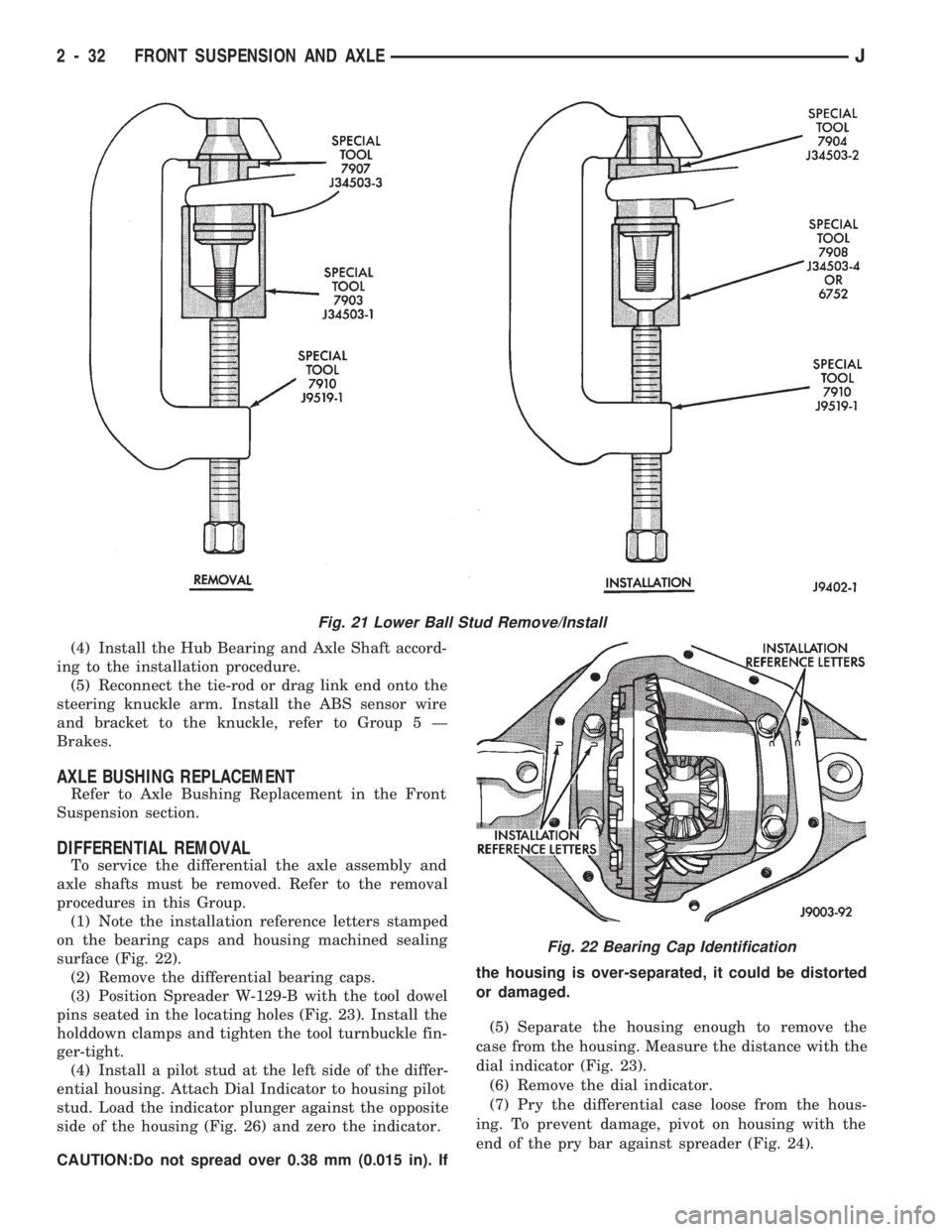
LOWER BALL STUD REPLACEMENT
(1) Position tools as shown to remove and install
ball stud (Fig.21). Because there are two different de-
signs for the lower ball studs try both installers for
proper fit.
KNUCKLE INSTALLATION
(1) Position the steering knuckle on the ball studs.
(2) Install and tighten the bottom retaining nut to
109 Nzm (80 ft. lbs.) torque. Install new cotter pins.
(3) Install and tighten the top retaining nut to 101
Nzm (75 ft. lbs.) torque. Install new cotter pin.
Fig. 19 Steering Knuckle Removal/Installation
Fig. 20 Upper Ball Stud Remove/Install
JFRONT SUSPENSION AND AXLE 2 - 31
Page 69 of 1784
(4) Install the Hub Bearing and Axle Shaft accord-
ing to the installation procedure.
(5) Reconnect the tie-rod or drag link end onto the
steering knuckle arm. Install the ABS sensor wire
and bracket to the knuckle, refer to Group 5 Ð
Brakes.
AXLE BUSHING REPLACEMENT
Refer to Axle Bushing Replacement in the Front
Suspension section.
DIFFERENTIAL REMOVAL
To service the differential the axle assembly and
axle shafts must be removed. Refer to the removal
procedures in this Group.
(1) Note the installation reference letters stamped
on the bearing caps and housing machined sealing
surface (Fig. 22).
(2) Remove the differential bearing caps.
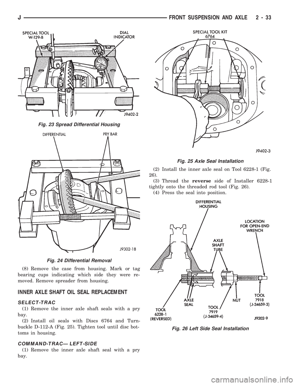
(3) Position Spreader W-129-B with the tool dowel
pins seated in the locating holes (Fig. 23). Install the
holddown clamps and tighten the tool turnbuckle fin-
ger-tight.
(4) Install a pilot stud at the left side of the differ-
ential housing. Attach Dial Indicator to housing pilot
stud. Load the indicator plunger against the opposite
side of the housing (Fig. 26) and zero the indicator.
CAUTION:Do not spread over 0.38 mm (0.015 in). Ifthe housing is over-separated, it could be distorted
or damaged.
(5) Separate the housing enough to remove the
case from the housing. Measure the distance with the
dial indicator (Fig. 23).
(6) Remove the dial indicator.
(7) Pry the differential case loose from the hous-
ing. To prevent damage, pivot on housing with the
end of the pry bar against spreader (Fig. 24).
Fig. 21 Lower Ball Stud Remove/Install
Fig. 22 Bearing Cap Identification
2 - 32 FRONT SUSPENSION AND AXLEJ
Page 70 of 1784
(8) Remove the case from housing. Mark or tag
bearing cups indicating which side they were re-
moved. Remove spreader from housing.
INNER AXLE SHAFT OIL SEAL REPLACEMENT
SELECT-TRAC
(1) Remove the inner axle shaft seals with a pry
bay.
(2) Install oil seals with Discs 6764 and Turn-
buckle D-112-A (Fig. 25). Tighten tool until disc bot-
toms in housing.
COMMAND-TRACÐ LEFT-SIDE
(1) Remove the inner axle shaft seal with a pry
bay.(2) Install the inner axle seal on Tool 6228-1 (Fig.
26).
(3) Thread thereverseside of Installer 6228-1
tightly onto the threaded rod tool (Fig. 26).
(4) Press the seal into position.
Fig. 23 Spread Differential Housing
Fig. 24 Differential Removal
Fig. 25 Axle Seal Installation
Fig. 26 Left Side Seal Installation
JFRONT SUSPENSION AND AXLE 2 - 33