drain bolt JEEP CHEROKEE 1994 Service Repair Manual
[x] Cancel search | Manufacturer: JEEP, Model Year: 1994, Model line: CHEROKEE, Model: JEEP CHEROKEE 1994Pages: 1784, PDF Size: 77.09 MB
Page 26 of 1784
DRAINING ATF/FILTER REMOVAL
Drain the automatic transmission fluid (ATF) im-
mediately after stopping the engine (before the ATF
cools).
(1) Raise and support the vehicle.
(2) Loosen the transmission pan bolts and drain
the original ATF into an appropriate container. Re-
move the pan bolts, the pan and the gasket.
Care should be exercised when disposing used
ATF after it has been drained from a vehicle
transmission.
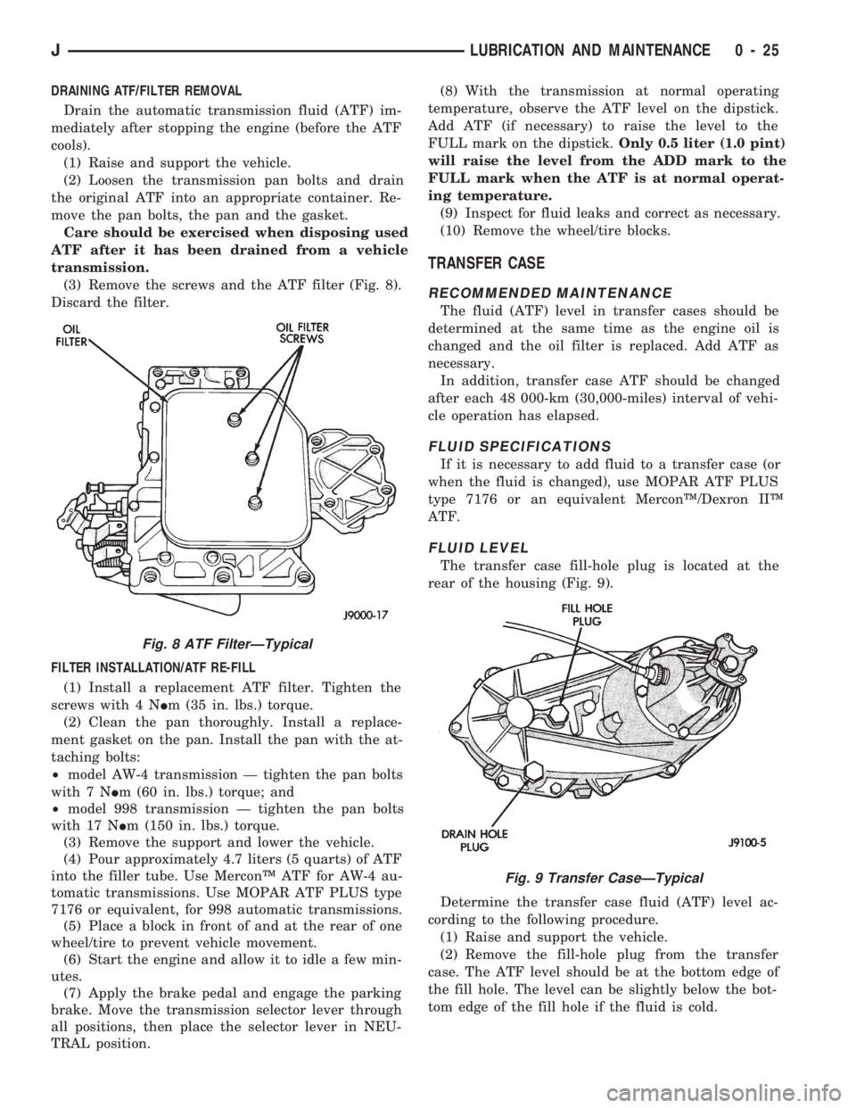
(3) Remove the screws and the ATF filter (Fig. 8).
Discard the filter.
FILTER INSTALLATION/ATF RE-FILL
(1) Install a replacement ATF filter. Tighten the
screws with 4 NIm (35 in. lbs.) torque.
(2) Clean the pan thoroughly. Install a replace-
ment gasket on the pan. Install the pan with the at-
taching bolts:
²model AW-4 transmission Ð tighten the pan bolts
with 7 NIm (60 in. lbs.) torque; and
²model 998 transmission Ð tighten the pan bolts
with 17 NIm (150 in. lbs.) torque.
(3) Remove the support and lower the vehicle.
(4) Pour approximately 4.7 liters (5 quarts) of ATF
into the filler tube. Use MerconŸ ATF for AW-4 au-
tomatic transmissions. Use MOPAR ATF PLUS type
7176 or equivalent, for 998 automatic transmissions.
(5) Place a block in front of and at the rear of one
wheel/tire to prevent vehicle movement.
(6) Start the engine and allow it to idle a few min-
utes.
(7) Apply the brake pedal and engage the parking
brake. Move the transmission selector lever through
all positions, then place the selector lever in NEU-
TRAL position.(8) With the transmission at normal operating
temperature, observe the ATF level on the dipstick.
Add ATF (if necessary) to raise the level to the
FULL mark on the dipstick.Only 0.5 liter (1.0 pint)
will raise the level from the ADD mark to the
FULL mark when the ATF is at normal operat-
ing temperature.
(9) Inspect for fluid leaks and correct as necessary.
(10) Remove the wheel/tire blocks.
TRANSFER CASE
RECOMMENDED MAINTENANCE
The fluid (ATF) level in transfer cases should be
determined at the same time as the engine oil is
changed and the oil filter is replaced. Add ATF as
necessary.
In addition, transfer case ATF should be changed
after each 48 000-km (30,000-miles) interval of vehi-
cle operation has elapsed.
FLUID SPECIFICATIONS
If it is necessary to add fluid to a transfer case (or
when the fluid is changed), use MOPAR ATF PLUS
type 7176 or an equivalent MerconŸ/Dexron IIŸ
ATF.
FLUID LEVEL
The transfer case fill-hole plug is located at the
rear of the housing (Fig. 9).
Determine the transfer case fluid (ATF) level ac-
cording to the following procedure.
(1) Raise and support the vehicle.
(2) Remove the fill-hole plug from the transfer
case. The ATF level should be at the bottom edge of
the fill hole. The level can be slightly below the bot-
tom edge of the fill hole if the fluid is cold.
Fig. 9 Transfer CaseÐTypical
Fig. 8 ATF FilterÐTypical
JLUBRICATION AND MAINTENANCE 0 - 25
Page 28 of 1784
LUBRICANT CHANGE
When it becomes necessary to change the axle lu-
bricant in a Jeeptfront or rear axle, use the follow-
ing procedure.
(1) Raise and support the vehicle.
(2) Place a container under the axle differential
housing.
(3) Remove the axle differential housing cover
bolts. Remove the housing cover.
(4) Allow the axle gear lubricant to completely
drain into the container.
CAUTION: Do not flush a rear axle Trac-Loc differ-
ential. Trac-Loc differentials may be cleaned only
by disassembling the unit and wiping the compo-
nents with clean, lint-free cloth.
(5) Flush the inside of the differential housing
with a flushing oil.Do not use water, steam, ker-
osene or gasoline for flushing.
(6) Remove any residual RTV sealant/gasket mate-
rial from the differential housing and cover. Thor-
oughly clean the contact surfaces with mineral
spirits and dry the surfaces completely.
(7) Apply a`bead of MOPAR RTV Sealant, or an
equivalent sealant, around the bolt circle on the
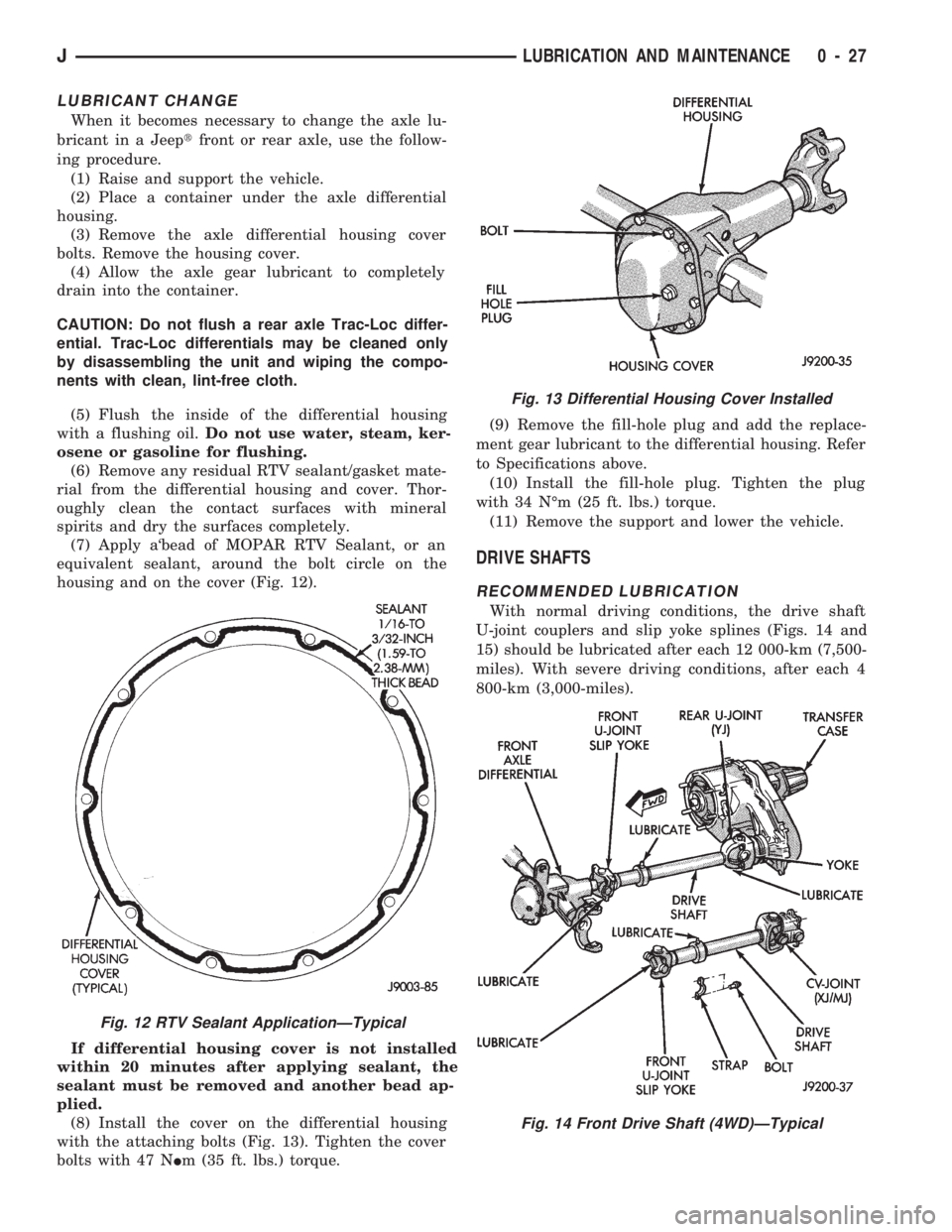
housing and on the cover (Fig. 12).
If differential housing cover is not installed
within 20 minutes after applying sealant, the
sealant must be removed and another bead ap-
plied.
(8) Install the cover on the differential housing
with the attaching bolts (Fig. 13). Tighten the cover
bolts with 47 NIm (35 ft. lbs.) torque.(9) Remove the fill-hole plug and add the replace-
ment gear lubricant to the differential housing. Refer
to Specifications above.
(10) Install the fill-hole plug. Tighten the plug
with 34 NÉm (25 ft. lbs.) torque.
(11) Remove the support and lower the vehicle.
DRIVE SHAFTS
RECOMMENDED LUBRICATION
With normal driving conditions, the drive shaft
U-joint couplers and slip yoke splines (Figs. 14 and
15) should be lubricated after each 12 000-km (7,500-
miles). With severe driving conditions, after each 4
800-km (3,000-miles).
Fig. 12 RTV Sealant ApplicationÐTypical
Fig. 13 Differential Housing Cover Installed
Fig. 14 Front Drive Shaft (4WD)ÐTypical
JLUBRICATION AND MAINTENANCE 0 - 27
Page 59 of 1784
(9) Disconnect the tie rod from the steering
knuckle. Disconnect the steering dampener from the
axle bracket.
(10) Support the axle with a hydraulic jack under
the differential. Raise the axle just enough to relieve
the axle weight from the springs.
(11) Remove the spring U-bolts from the plate
brackets.
(12) Loosen BUT DO NOT REMOVE the bolts that
attach the spring rear pivot at the frame rail brack-
ets. This will allow the springs to pivot without bind-
ing on the bushings.
(13) Disconnect shackle from the springs and lower
the springs to the surface.
(14) Lower the jack enough to remove the axle.
INSTALLATION
CAUTION: All suspension components that use rub-
ber bushings should be tightened with the vehicle
at the normal height. It is important to have the
springs supporting the weight of the vehicle when
the fasteners are torqued. If the springs are not at
their normal ride position, vehicle ride comfort
could be affected along with premature rubber
bushing wear. Rubber bushings must never be lu-
bricated.
(1) Support the axle on a hydraulic jack under the
differential. Position the axle under the vehicle.
(2) Raise the springs and install the spring shackle
bolts.Do not tighten at this time.
(3) Lower the axle and align the spring center
bolts with the locating holes in the axle pads and
plate brackets.
(4) Install the spring U-bolts through the plate
brackets and tighten to 122 Nzm (90 ft. lbs.) torque.
(5) Connect the track bar to the axle bracket and
install the bolt.Do not tighten at this time.
It is important that the springs support the
weight of the vehicle when the track bar is con-
nected. If the springs are not at their usual po-
sition, the vehicle ride comfort could be affected.
(6) Install the shock absorber and tighten the nut
to 61 Nzm (45 ft. lbs.) torque.
(7) Install the stabilizer bar link to the axle
bracket. Tighten the nut to 61 Nzm (45 ft. lbs.)
torque.
(8) Install the tie rod to the steering knuckles and
tighten the nuts to 47 Nzm (35 ft. lbs.) torque. Install
the steering dampener to the axle bracket and
tighten the bolt to 75 Nzm (55 ft. lbs.) torque.
(9) Install the brake components and ABS brake
sensor (if equipped). Refer to Group 5ÐBrakes.
(10) Connect the vent hose to the tube fitting and
axle shift motor vacuum harness.(11) Align the reference marks and connect the
drive shaft to the axle yoke. Tighten the U-joint
clamp bolts to 19 Nzm (14 ft. lbs.) torque.
(12) Check differential lubricant and add if neces-
sary.
(13) Install the wheel and tire assemblies.
(14) Remove the supports and lower the vehicle.
(15) Tighten the spring rear pivot bolt/nut to 142
Nzm (105 ft. lbs.) torque. Tighten the spring shackle
bolt/nut to 135 Nzm (100 ft. lbs.) torque.
(16) Tighten the track bar nut at the axle bracket
to 100 Nzm (74 ft. lbs.) torque.
(17) Check the front wheel alignment.
LUBRICANT CHANGE
The gear lubricant will drain quicker if the vehicle
has been recently driven.
(1) Raise and support the vehicle.
(2) Remove the lubricant fill hole plug from the
differential housing cover.
(3) Remove the differential housing cover and
drain the lubricant from the housing.
(4) Clean the housing cavity with a flushing oil,
light engine oil or lint free cloth.Do not use water,
steam, kerosene or gasoline for cleaning.
(5) Remove the sealant from the housing and cover
surfaces. Use solvent to clean the mating surfaces.
(6) Apply a bead of MOPARtSilicone Rubber Seal-
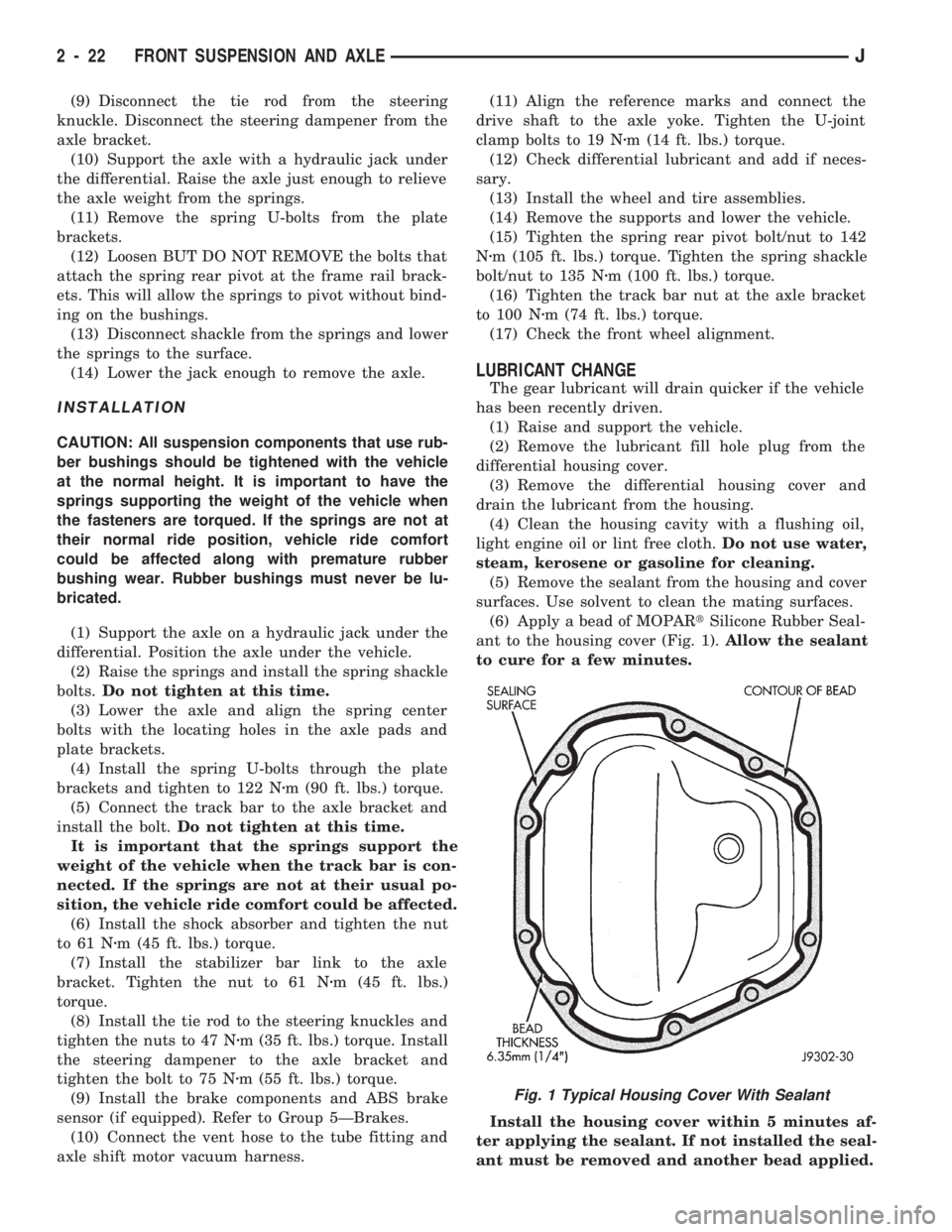
ant to the housing cover (Fig. 1).Allow the sealant
to cure for a few minutes.
Install the housing cover within 5 minutes af-
ter applying the sealant. If not installed the seal-
ant must be removed and another bead applied.
Fig. 1 Typical Housing Cover With Sealant
2 - 22 FRONT SUSPENSION AND AXLEJ
Page 100 of 1784
INSTALLATIONÐYJ MODELS
(1) Place tank into skid plate. Wrap straps around
tank with strap bolts inserted through holes in skid
plate. Tighten strap nuts to 7.3 Nzm (65 in. lbs.) torque.
(2) Raise skid plate/fuel tank until gauge sender wire
connector can be connected to harness connector.
(3) Finish raising skid plate/fuel tank assembly
into position. Tighten mounting nuts to 16 Nzm (12
ft. lbs.) torque. Remove transmission jack.
(4) Connect fuel fill hose and fill vent hose to filler
neck. Tighten hose clamps.
(5) Connect vent hose to vent tube.
(6) Connect fuel supply hose to the supply tube and
fuel return hose to return tube. Tighten hose clamps.
(7) Install fuel filler neck shroud with push clips.
(8) Lower vehicle.
(9) Fill fuel tank. Install filler cap.
(10) Connect negative battery cable to battery.
(11) Start vehicle and inspect for leaks.
FUEL GAUGE SENDING UNIT
The fuel gauge sending unit is attached to the fuel
pump module. Refer to Fuel Pump Module in the
Fuel Delivery System section of this group.
FUEL TANK PRESSURE RELIEF/ROLLOVER VALVE
The fuel tank is equipped with a pressure relief/
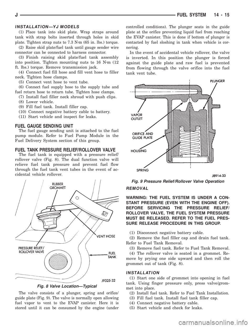
rollover valve (Fig. 8). The dual function valve will
relieve fuel tank pressure and prevent fuel flow
through the fuel tank vent tubes in the event of ac-
cidental vehicle rollover.
The valve consists of a plunger, spring and orifice/
guide plate (Fig. 9). The valve is normally open allowing
fuel vapor to vent to the EVAP canister. Here it is
stored until it can be consumed by the engine (undercontrolled conditions). The plunger seats in the guide
plate at the orifice preventing liquid fuel from reaching
the EVAP canister. This is done if bottom of plunger is
contacted by fuel sloshing in tank when vehicle is cor-
nering.
In the event of accidental vehicle rollover, the valve
is inverted. In this position the plunger is forced
against the guide plate and raw fuel is prevented
from flowing through the valve orifice into the fuel
tank vent tube.
REMOVAL
WARNING: THE FUEL SYSTEM IS UNDER A CON-
STANT PRESSURE (EVEN WITH THE ENGINE OFF).
BEFORE SERVICING THE PRESSURE RELIEF/
ROLLOVER VALVE, THE FUEL SYSTEM PRESSURE
MUST BE RELEASED. REFER TO THE FUEL PRES-
SURE RELEASE PROCEDURE IN THIS GROUP.
(1) Disconnect negative battery cable.
(2) Remove the fuel filler cap and drain fuel tank.
Refer to Fuel Tank Removal.
(3) Remove fuel tank. Refer to Fuel Tank Removal.
(4) The rollover valve is seated in a grommet. Re-
move by prying one side upward and then roll the
grommet out of tank (Fig. 8).
INSTALLATION
(1) Start one side of grommet into opening in fuel
tank. Using finger pressure only, press valve/grom-
met into place.
(2) Install fuel tank. Refer to Fuel Tank Installation.
(3) Fill fuel tank. Install fuel tank filler cap.
(4) Connect negative battery cable.
(5) Start vehicle and check for leaks.
Fig. 8 Valve LocationÐTypical
Fig. 9 Pressure Relief/Rollover Valve Operation
JFUEL SYSTEM 14 - 15
Page 149 of 1784
Use Mopar Multi Mileage grease to lubricate drum
brake pivot pins and rear brakeshoe contact points
on the support plates. Use GE 661, or Dow 111 sili-
cone grease on caliper bushings and mounting bolts.
Use fresh brake fluid or Mopar brake cleaner to
clean or flush brake system components. These are
the only cleaning materials recommended.
CAUTION: Never use gasoline, kerosene, methyl or
isopropyl alcohol, paint thinner, or any fluid con-
taining mineral oil to clean the system components.
These fluids damage rubber cups and seals. If sys-
tem contamination is suspected, check the fluid for
dirt, discoloration, or separation into distinct layers.
Drain and flush the system with new brake fluid if
contamination is suspected.
JEEP BODY CODE LETTERS
The body/model identification code letters for Jeep
vehicles are as follows:
²Code letters XJ: Cherokee
²Code letters YJ: Wrangler/YJ
The code letters are used throughout this group to
simplify model identification and component applica-
tion.
BRAKE SAFETY PRECAUTIONS
WARNING: ALTHOUGH FACTORY INSTALLED
BRAKELINING ON JEEP VEHICLES IS MADE FROM
ASBESTOS FREE MATERIALS, SOME AFTER MARKET
BRAKELINING MAY CONTAIN ASBESTOS. THIS
SHOULD BE TAKEN INTO ACCOUNT WHEN REPAIR-
ING A VEHICLE WITH PRIOR BRAKE SERVICE. WEAR
A RESPIRATOR WHEN CLEANING BRAKE COMPO-
NENTS AS ASBESTOS FIBERS CAN BE A HEALTH
HAZARD. NEVER CLEAN WHEEL BRAKE COMPO-
NENTS WITH COMPRESSED AIR. USE A VACUUM
CLEANER SPECIFICALLY DESIGNED FOR REMOVING
BRAKE DUST. IF A VACUUM CLEANER IS NOT AVAIL-
ABLE, CLEAN THE PARTS WITH WATER DAMPENED
SHOP RAGS. DO NOT CREATE DUST BY SANDING
BRAKELINING. DISPOSE OF ALL DUST AND DIRT
SUSPECTED OF CONTAINING ASBESTOS FIBERS IN
SEALED BAGS OR CONTAINERS. FOLLOW ALL REC-
OMMENDED SAFETY PRACTICES PRESCRIBED BY
THE OCCUPATIONAL SAFETY AND HEALTH ADMINIS-
TRATION (OSHA) AND THE ENVIRONMENTAL PRO-
TECTION AGENCY (EPA), FOR HANDLING AND
DISPOSAL OF PRODUCTS CONTAINING ASBESTOS.
5 - 2 BRAKESJ
Page 172 of 1784
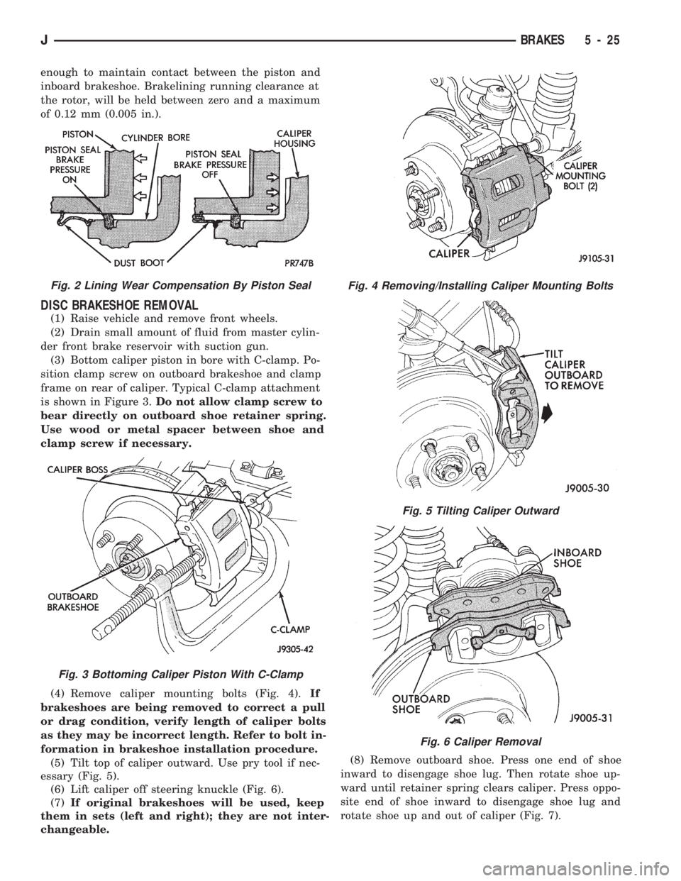
enough to maintain contact between the piston and
inboard brakeshoe. Brakelining running clearance at
the rotor, will be held between zero and a maximum
of 0.12 mm (0.005 in.).
DISC BRAKESHOE REMOVAL
(1) Raise vehicle and remove front wheels.
(2) Drain small amount of fluid from master cylin-
der front brake reservoir with suction gun.
(3) Bottom caliper piston in bore with C-clamp. Po-
sition clamp screw on outboard brakeshoe and clamp
frame on rear of caliper. Typical C-clamp attachment
is shown in Figure 3.Do not allow clamp screw to
bear directly on outboard shoe retainer spring.
Use wood or metal spacer between shoe and
clamp screw if necessary.
(4) Remove caliper mounting bolts (Fig. 4).If
brakeshoes are being removed to correct a pull
or drag condition, verify length of caliper bolts
as they may be incorrect length. Refer to bolt in-
formation in brakeshoe installation procedure.
(5) Tilt top of caliper outward. Use pry tool if nec-
essary (Fig. 5).
(6) Lift caliper off steering knuckle (Fig. 6).
(7)If original brakeshoes will be used, keep
them in sets (left and right); they are not inter-
changeable.(8) Remove outboard shoe. Press one end of shoe
inward to disengage shoe lug. Then rotate shoe up-
ward until retainer spring clears caliper. Press oppo-
site end of shoe inward to disengage shoe lug and
rotate shoe up and out of caliper (Fig. 7).
Fig. 2 Lining Wear Compensation By Piston Seal
Fig. 3 Bottoming Caliper Piston With C-Clamp
Fig. 4 Removing/Installing Caliper Mounting Bolts
Fig. 5 Tilting Caliper Outward
Fig. 6 Caliper Removal
JBRAKES 5 - 25
Page 197 of 1784
(2) Raise vehicle.
(3) Disconnect sensor wires at rear axle connectors.
(4) Remove wheel and tire assembly.
(5) Remove brake drum.
(6) Remove clips securing sensor wires to brake
lines or rear axle and rear brake hose.
(7) Unseat sensor support plate grommet.
(8) Remove bolt attaching sensor to bracket and
remove sensor.
REAR WHEEL SENSOR INSTALLATION
(1) Insert sensor wire through support plate hole
and seat sensor grommet in support plate.
(2) Apply Mopar Lock N' Seal or Loctite 242 to
original sensor bolt. Use new bolt if original is worn
or damaged.
(3) Install sensor bolt finger tight only at this
time.
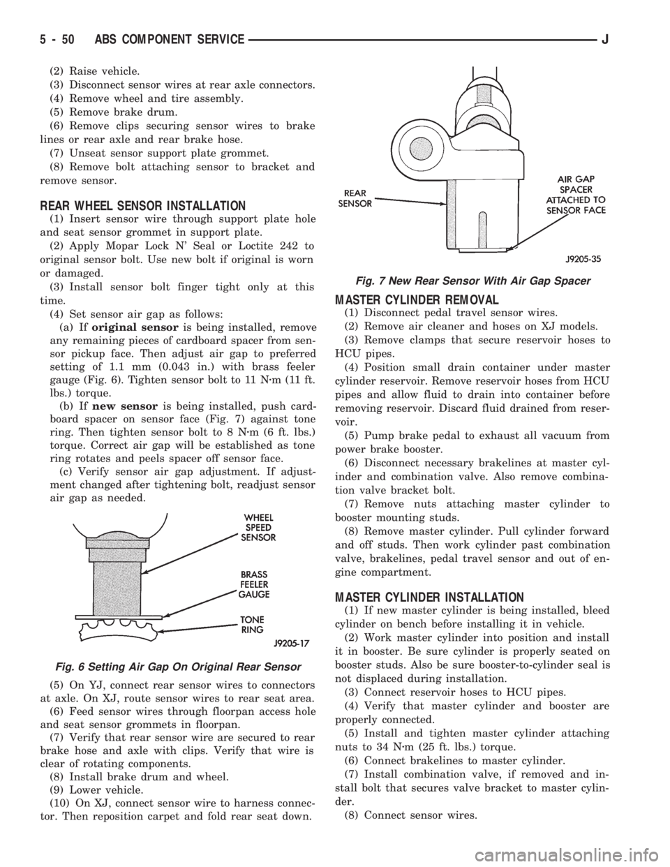
(4) Set sensor air gap as follows:
(a) Iforiginal sensoris being installed, remove
any remaining pieces of cardboard spacer from sen-
sor pickup face. Then adjust air gap to preferred
setting of 1.1 mm (0.043 in.) with brass feeler
gauge (Fig. 6). Tighten sensor bolt to 11 Nzm (11 ft.
lbs.) torque.
(b) Ifnew sensoris being installed, push card-
board spacer on sensor face (Fig. 7) against tone
ring. Then tighten sensor bolt to 8 Nzm (6 ft. lbs.)
torque. Correct air gap will be established as tone
ring rotates and peels spacer off sensor face.
(c) Verify sensor air gap adjustment. If adjust-
ment changed after tightening bolt, readjust sensor
air gap as needed.
(5) On YJ, connect rear sensor wires to connectors
at axle. On XJ, route sensor wires to rear seat area.
(6) Feed sensor wires through floorpan access hole
and seat sensor grommets in floorpan.
(7) Verify that rear sensor wire are secured to rear
brake hose and axle with clips. Verify that wire is
clear of rotating components.
(8) Install brake drum and wheel.
(9) Lower vehicle.
(10) On XJ, connect sensor wire to harness connec-
tor. Then reposition carpet and fold rear seat down.
MASTER CYLINDER REMOVAL
(1) Disconnect pedal travel sensor wires.
(2) Remove air cleaner and hoses on XJ models.
(3) Remove clamps that secure reservoir hoses to
HCU pipes.
(4) Position small drain container under master
cylinder reservoir. Remove reservoir hoses from HCU
pipes and allow fluid to drain into container before
removing reservoir. Discard fluid drained from reser-
voir.
(5) Pump brake pedal to exhaust all vacuum from
power brake booster.
(6) Disconnect necessary brakelines at master cyl-
inder and combination valve. Also remove combina-
tion valve bracket bolt.
(7) Remove nuts attaching master cylinder to
booster mounting studs.
(8) Remove master cylinder. Pull cylinder forward
and off studs. Then work cylinder past combination
valve, brakelines, pedal travel sensor and out of en-
gine compartment.
MASTER CYLINDER INSTALLATION
(1) If new master cylinder is being installed, bleed
cylinder on bench before installing it in vehicle.
(2) Work master cylinder into position and install
it in booster. Be sure cylinder is properly seated on
booster studs. Also be sure booster-to-cylinder seal is
not displaced during installation.
(3) Connect reservoir hoses to HCU pipes.
(4) Verify that master cylinder and booster are
properly connected.
(5) Install and tighten master cylinder attaching
nuts to 34 Nzm (25 ft. lbs.) torque.
(6) Connect brakelines to master cylinder.
(7) Install combination valve, if removed and in-
stall bolt that secures valve bracket to master cylin-
der.
(8) Connect sensor wires.
Fig. 6 Setting Air Gap On Original Rear Sensor
Fig. 7 New Rear Sensor With Air Gap Spacer
5 - 50 ABS COMPONENT SERVICEJ
Page 200 of 1784
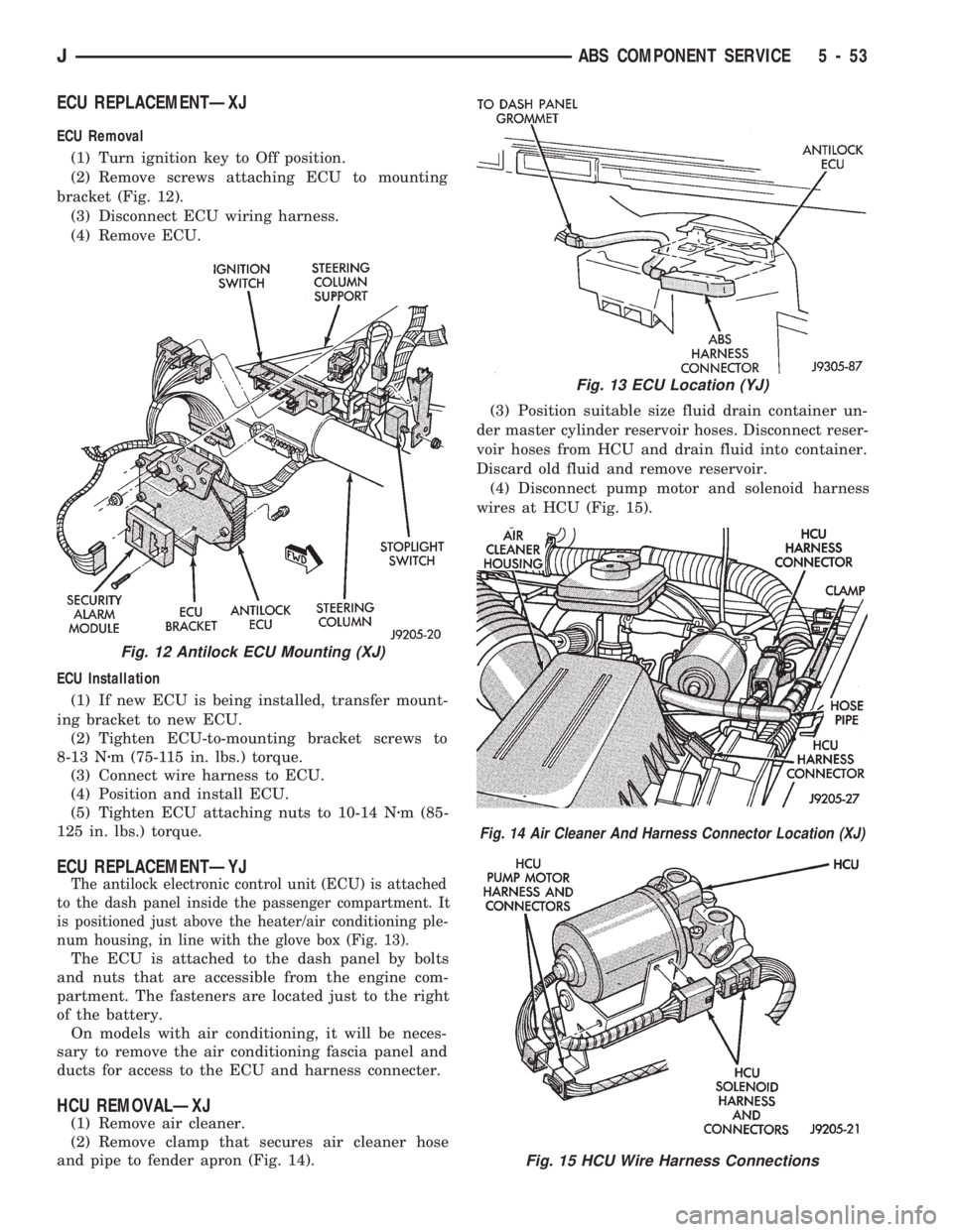
ECU REPLACEMENTÐXJ
ECU Removal
(1) Turn ignition key to Off position.
(2) Remove screws attaching ECU to mounting
bracket (Fig. 12).
(3) Disconnect ECU wiring harness.
(4) Remove ECU.
ECU Installation
(1) If new ECU is being installed, transfer mount-
ing bracket to new ECU.
(2) Tighten ECU-to-mounting bracket screws to
8-13 Nzm (75-115 in. lbs.) torque.
(3) Connect wire harness to ECU.
(4) Position and install ECU.
(5) Tighten ECU attaching nuts to 10-14 Nzm (85-
125 in. lbs.) torque.
ECU REPLACEMENTÐYJ
The antilock electronic control unit (ECU) is attached
to the dash panel inside the passenger compartment. It
is positioned just above the heater/air conditioning ple-
num housing, in line with the glove box (Fig. 13).
The ECU is attached to the dash panel by bolts
and nuts that are accessible from the engine com-
partment. The fasteners are located just to the right
of the battery.
On models with air conditioning, it will be neces-
sary to remove the air conditioning fascia panel and
ducts for access to the ECU and harness connecter.
HCU REMOVALÐXJ
(1) Remove air cleaner.
(2) Remove clamp that secures air cleaner hose
and pipe to fender apron (Fig. 14).(3) Position suitable size fluid drain container un-
der master cylinder reservoir hoses. Disconnect reser-
voir hoses from HCU and drain fluid into container.
Discard old fluid and remove reservoir.
(4) Disconnect pump motor and solenoid harness
wires at HCU (Fig. 15).
Fig. 12 Antilock ECU Mounting (XJ)
Fig. 13 ECU Location (YJ)
Fig. 14 Air Cleaner And Harness Connector Location (XJ)
Fig. 15 HCU Wire Harness Connections
JABS COMPONENT SERVICE 5 - 53
Page 243 of 1784
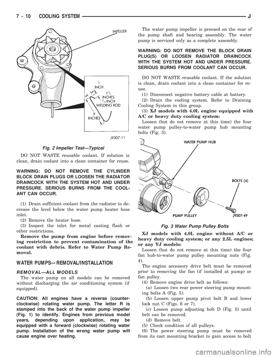
DO NOT WASTE reusable coolant. If solution is
clean, drain coolant into a clean container for reuse.
WARNING: DO NOT REMOVE THE CYLINDER
BLOCK DRAIN PLUGS OR LOOSEN THE RADIATOR
DRAINCOCK WITH THE SYSTEM HOT AND UNDER
PRESSURE. SERIOUS BURNS FROM THE COOL-
ANT CAN OCCUR.
(1) Drain sufficient coolant from the radiator to de-
crease the level below the water pump heater hose
inlet.
(2) Remove the heater hose.
(3) Inspect the inlet for metal casting flash or
other restrictions.
Remove the pump from engine before remov-
ing restriction to prevent contamination of the
coolant with debris. Refer to Water Pump Re-
moval.
WATER PUMPSÐREMOVAL/INSTALLATION
REMOVALÐALL MODELS
The water pump on all models can be removed
without discharging the air conditioning system (if
equipped).
CAUTION: All engines have a reverse (counter-
clockwise) rotating water pump. The letter R is
stamped into the back of the water pump impeller
(Fig. 1) to identify. Engines from previous model
years, depending upon application, may be
equipped with a forward (clockwise) rotating water
pump. Installation of the wrong water pump will
cause engine over heating.The water pump impeller is pressed on the rear of
the pump shaft and bearing assembly. The water
pump is serviced only as a complete assembly.
WARNING: DO NOT REMOVE THE BLOCK DRAIN
PLUG(S) OR LOOSEN RADIATOR DRAINCOCK
WITH THE SYSTEM HOT AND UNDER PRESSURE.
SERIOUS BURNS FROM COOLANT CAN OCCUR.
DO NOT WASTE reusable coolant. If the solution
is clean, drain coolant into a clean container for re-
use.
(1) Disconnect negative battery cable at battery.
(2) Drain the cooling system. Refer to Draining
Cooling System in this group.
(3)XJ models with 4.0L engine equipped with
A/C or heavy duty cooling system:
Loosen (but do not remove at this time) the four
water pump pulley-to-water pump hub mounting
bolts (Fig. 3).
XJ models with 4.0L engine without A/C or
heavy duty cooling system; or any 2.5L engines;
or any YJ models:
Loosen (but do not remove at this time) the four
fan hub-to-water pump pulley mounting nuts (Fig.
4).
The engine accessory drive belt must be removed
prior to removing the fan (if installed at pump) or
fan pulley.
(4) Remove engine drive belt as follows:
(a) Loosen two rear power steering pump mount-
ing bolts A (Fig. 5).
(b) Loosen upper pump pivot bolt B and lower
lock nut C (Figs. 6 or 7).
(c) Loosen pump adjusting bolt D (Fig. 5) until
belt can be removed.
(d) Remove belt.
(5) Check condition of all pulleys.
(6) The power steering pump must be removed
from its cast mounting bracket to gain access to bolt
Fig. 2 Impeller TestÐTypical
Fig. 3 Water Pump Pulley Bolts
7 - 10 COOLING SYSTEMJ
Page 247 of 1784
CAUTION: Do not operate an engine without a ther-
mostat, except for servicing or testing.
ON-BOARD DIAGNOSTICS
XJ and YJ models are equipped with On-Board Di-
agnostics for certain cooling system components. Re-
fer to On-Board Diagnostics (OBD) in the Diagnosis
section of this group for additional information. If the
powertrain control module (PCM) detects low engine
coolant temperature, it will record a Diagnostic Trou-
ble Code (DTC) in the PCM memory. The DTC num-
ber for low coolant temperature is 17. Do not change
a thermostat for lack of heat as indicated by the in-
strument panel gauge or heater performance unless a
DTC number 17 is present. Refer to the Diagnosis
section of this group for other probable causes. For
other DTC numbers, refer to On-Board Diagnostics
in the General Diagnosis section of group 14, Fuel
Systems.
The DTC can also be accessed through the DRB
scan tool. Refer to the appropriate Powertrain Diag-
nostic Procedures manual for diagnostic information
and operation of the DRB scan tool.
REMOVAL
WARNING: DO NOT LOOSEN THE RADIATOR
DRAINCOCK WITH THE SYSTEM HOT AND PRES-
SURIZED. SERIOUS BURNS FROM THE COOLANT
CAN OCCUR.
DO NOT WASTE reusable coolant. If the solution
is clean, drain the coolant into a clean container for
reuse.
(1) Drain the coolant from the radiator until the
level is below the thermostat housing.
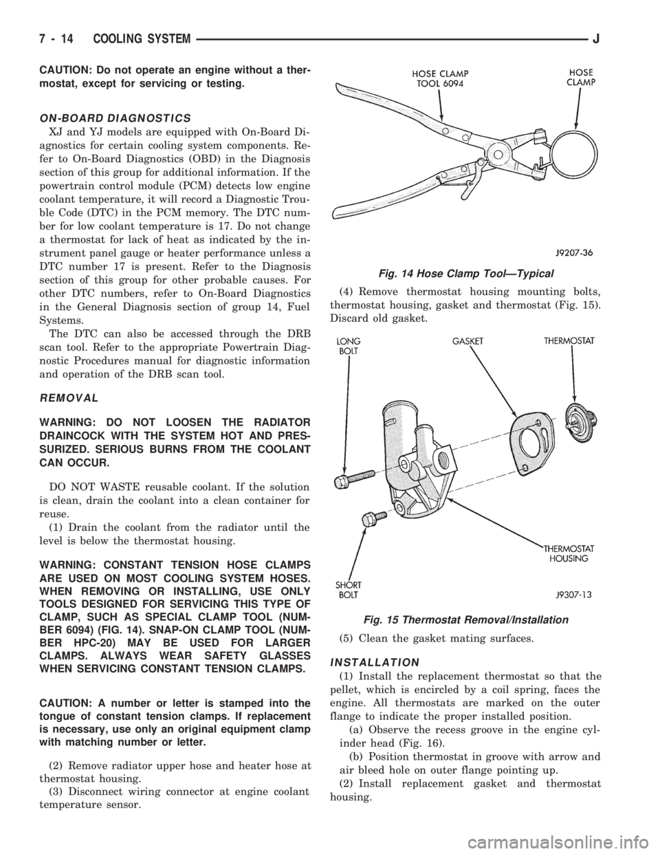
WARNING: CONSTANT TENSION HOSE CLAMPS
ARE USED ON MOST COOLING SYSTEM HOSES.
WHEN REMOVING OR INSTALLING, USE ONLY
TOOLS DESIGNED FOR SERVICING THIS TYPE OF
CLAMP, SUCH AS SPECIAL CLAMP TOOL (NUM-
BER 6094) (FIG. 14). SNAP-ON CLAMP TOOL (NUM-
BER HPC-20) MAY BE USED FOR LARGER
CLAMPS. ALWAYS WEAR SAFETY GLASSES
WHEN SERVICING CONSTANT TENSION CLAMPS.
CAUTION: A number or letter is stamped into the
tongue of constant tension clamps. If replacement
is necessary, use only an original equipment clamp
with matching number or letter.
(2) Remove radiator upper hose and heater hose at
thermostat housing.
(3) Disconnect wiring connector at engine coolant
temperature sensor.(4) Remove thermostat housing mounting bolts,
thermostat housing, gasket and thermostat (Fig. 15).
Discard old gasket.
(5) Clean the gasket mating surfaces.
INSTALLATION
(1) Install the replacement thermostat so that the
pellet, which is encircled by a coil spring, faces the
engine. All thermostats are marked on the outer
flange to indicate the proper installed position.
(a) Observe the recess groove in the engine cyl-
inder head (Fig. 16).
(b) Position thermostat in groove with arrow and
air bleed hole on outer flange pointing up.
(2) Install replacement gasket and thermostat
housing.
Fig. 14 Hose Clamp ToolÐTypical
Fig. 15 Thermostat Removal/Installation
7 - 14 COOLING SYSTEMJ