front JEEP CHEROKEE 1994 Service Repair Manual
[x] Cancel search | Manufacturer: JEEP, Model Year: 1994, Model line: CHEROKEE, Model: JEEP CHEROKEE 1994Pages: 1784, PDF Size: 77.09 MB
Page 2 of 1784
LUBRICATION AND MAINTENANCE
CONTENTS
page page
CHASSIS AND BODY COMPONENTS....... 30
DRIVETRAIN........................... 22
ENGINE MAINTENANCE.................. 13GENERAL INFORMATION.................. 1
JUMP STARTING, HOISTING AND TOWING . . 7
MAINTENANCE SCHEDULES............... 5
GENERAL INFORMATION
INDEX
page page
Classification of Lubricants.................. 2
Components Requiring No Lubrication.......... 3
Fluid Capacities.......................... 4
Fuel Requirements........................ 2Introduction.............................. 1
Recommended Lubricant and Replacement Parts . 3
Routine Service........................... 2
INTRODUCTION
Jeeptlubrication and maintenance is divided into
required and recommended service tasks.
The recommendations and procedures listed in this
group are intended for JeeptDealer Service Personnel.
Because conditions vary, it is necessary to schedule
service tasks according to a time interval as well as a
distance interval.
It is the owner's responsibility to have vehicle ser-
viced. Owner is to pay for labor and necessary parts
that are not covered by the warranty.
Additional lubrication and maintenance informa-
tion is listed in the Owner's Manual, which is in-
cluded with the vehicle.
SEVERE DRIVING CONDITIONS
When a vehicle is subjected to a severe driving con-
dition, time between recommended maintenance
should be decreased.
Refer to Engine Maintenance for the engine oil and
filter maintenance interval when involved with a se-
vere driving condition.
A severe driving condition is defined as either:
²frequent short trip driving less than 24 km (15
miles);
²frequent driving in a dusty environment;
²trailer towing;
²extensive engine idling;
²sustained high-speed operation;
²desert operation;
²frequent starting and stopping;²cold-climate operation;
²off-road driving; or
²commercial service.
To service a Jeeptvehicle for a severe driving con-
dition, change all the lubricating fluids and lubricate:
²the body components,
²all the driveline coupling joints, and
²the steering linkage
more often than for a normal driving condition to
prevent excessive wear of the components.
DUSTY AREAS
Driving in an area with dust-filled air increases the
risk of particles entering the engine and crankcase.
With this type of severe driving condition, attention
should be given to the engine and crankcase compo-
nents.
OFF-ROAD (4WD) OPERATION
After completion of off-road (4WD) operation, the
underside of the vehicle should be thoroughly in-
spected. Examine threaded fasteners for looseness.
HARSH SURFACE ENVIRONMENTS
After vehicle operation in a harsh surface environ-
ment, the following components should be inspected
and cleaned as soon as possible:
²brake drums,
²brake linings,
²front wheel bearings (2WD vehicles only), and
²axle coupling joints.
This will prevent wear and/or unpredictable brake
action.
JLUBRICATION AND MAINTENANCE 0 - 1
Page 9 of 1784
PORTABLE STARTING UNIT
There are many types of portable starting units
available for starting engines. Follow the manufac-
turer's instructions when involved in any engine
starting procedure.
HOISTING RECOMMENDATIONS
FLOOR JACK
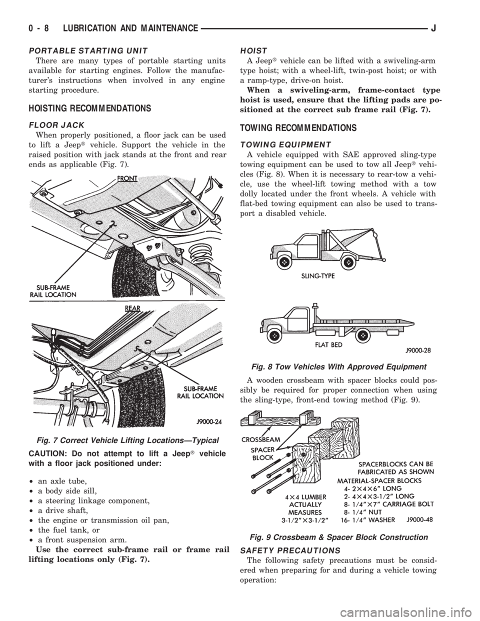
When properly positioned, a floor jack can be used
to lift a Jeeptvehicle. Support the vehicle in the
raised position with jack stands at the front and rear
ends as applicable (Fig. 7).
CAUTION: Do not attempt to lift a JeepTvehicle
with a floor jack positioned under:
²an axle tube,
²a body side sill,
²a steering linkage component,
²a drive shaft,
²the engine or transmission oil pan,
²the fuel tank, or
²a front suspension arm.
Use the correct sub-frame rail or frame rail
lifting locations only (Fig. 7).
HOIST
A Jeeptvehicle can be lifted with a swiveling-arm
type hoist; with a wheel-lift, twin-post hoist; or with
a ramp-type, drive-on hoist.
When a swiveling-arm, frame-contact type
hoist is used, ensure that the lifting pads are po-
sitioned at the correct sub frame rail (Fig. 7).
TOWING RECOMMENDATIONS
TOWING EQUIPMENT
A vehicle equipped with SAE approved sling-type
towing equipment can be used to tow all Jeeptvehi-
cles (Fig. 8). When it is necessary to rear-tow a vehi-
cle, use the wheel-lift towing method with a tow
dolly located under the front wheels. A vehicle with
flat-bed towing equipment can also be used to trans-
port a disabled vehicle.
A wooden crossbeam with spacer blocks could pos-
sibly be required for proper connection when using
the sling-type, front-end towing method (Fig. 9).
SAFETY PRECAUTIONS
The following safety precautions must be consid-
ered when preparing for and during a vehicle towing
operation:
Fig. 7 Correct Vehicle Lifting LocationsÐTypical
Fig. 8 Tow Vehicles With Approved Equipment
Fig. 9 Crossbeam & Spacer Block Construction
0 - 8 LUBRICATION AND MAINTENANCEJ
Page 10 of 1784
²if the vehicle is damaged, secure the loose and pro-
truding parts;
²always use a safety chain system that is indepen-
dent of the lifting and towing equipment;
²do not allow any of the towing equipment to con-
tact the disabled vehicle's fuel tank;
²do not allow anyone to be under the disabled vehi-
cle while it is lifted by the towing equipment;
²do not allow passengers to ride in a vehicle being
towed;
²always observe all state and local laws involving
warning signals, night illumination, speed, etc.
²do not attempt a towing operation that could jeop-
ardize the safety of the operator, bystanders or other
motorists;
²do not exceed a towing speed of 48 km/h (30 mph);
²avoid towing distances of more than 24 km (15
miles) whenever possible; and
²do not attach tow chains or a tow sling to a
bumper, the steering linkage, the universal joints,
the constant velocity (CV) joints, or a drive shaft.
CLEARANCES AND RAMP ANGLE
SURFACE CLEARANCE
The end of the disabled vehicle that is attached to
the tow vehicle should be lifted a minimum of 10 cm
or four inches off the surface. Inspect to ensure that
the opposite end of the disabled vehicle has clearance
from the surface.
RAMP ANGLEÐFLAT-BED TOWING
If a vehicle with flat-bed towing equipment is used,
the approach ramp angle should not exceed 15 de-
grees.
SLING-TYPE, FRONT-END TOWING
XJ VEHICLES
Use the following guidelines when the tow vehicle
is attached to the front end of a disabled vehicle.
(1) Always tow with the front wheels lifted off the
surface and turned all the way to the right.
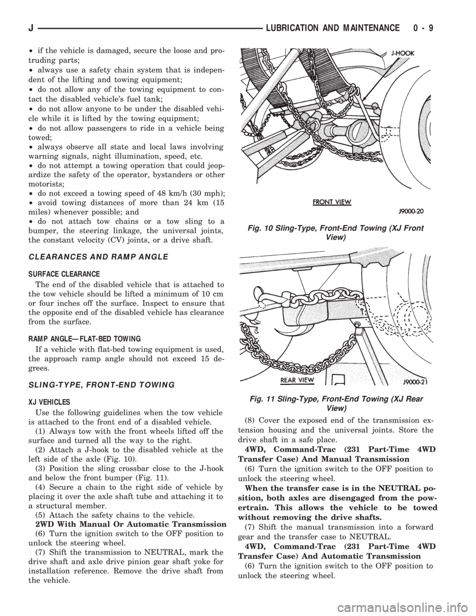
(2) Attach a J-hook to the disabled vehicle at the
left side of the axle (Fig. 10).
(3) Position the sling crossbar close to the J-hook
and below the front bumper (Fig. 11).
(4) Secure a chain to the right side of vehicle by
placing it over the axle shaft tube and attaching it to
a structural member.
(5) Attach the safety chains to the vehicle.
2WD With Manual Or Automatic Transmission
(6) Turn the ignition switch to the OFF position to
unlock the steering wheel.
(7) Shift the transmission to NEUTRAL, mark the
drive shaft and axle drive pinion gear shaft yoke for
installation reference. Remove the drive shaft from
the vehicle.(8) Cover the exposed end of the transmission ex-
tension housing and the universal joints. Store the
drive shaft in a safe place.
4WD, Command-Trac (231 Part-Time 4WD
Transfer Case) And Manual Transmission
(6) Turn the ignition switch to the OFF position to
unlock the steering wheel.
When the transfer case is in the NEUTRAL po-
sition, both axles are disengaged from the pow-
ertrain. This allows the vehicle to be towed
without removing the drive shafts.
(7) Shift the manual transmission into a forward
gear and the transfer case to NEUTRAL.
4WD, Command-Trac (231 Part-Time 4WD
Transfer Case) And Automatic Transmission
(6) Turn the ignition switch to the OFF position to
unlock the steering wheel.
Fig. 10 Sling-Type, Front-End Towing (XJ Front
View)
Fig. 11 Sling-Type, Front-End Towing (XJ Rear
View)
JLUBRICATION AND MAINTENANCE 0 - 9
Page 11 of 1784
When the transfer case is in the NEUTRAL po-
sition, both axles are disengaged from the pow-
ertrain. This allows the vehicle to be towed
without removing the drive shafts.
(7) Shift the automatic transmission to PARK and
the transfer case to NEUTRAL.
4WD, Selec-Trac (242 Full-Time 4WD Transfer
Case) And Automatic Transmission
(6) Turn the ignition switch to the OFF position to
unlock the steering wheel.
When the transfer case is in the NEUTRAL po-
sition, both axles are disengaged from the pow-
ertrain. This allows the vehicle to be towed
without removing the drive shafts.
(7) Shift the automatic transmission to PARK and
the transfer case to NEUTRAL.
YJ VEHICLES
Use the following guidelines when the tow vehicle
is attached to the front of a disabled vehicle.
(1) Always tow with the front wheels lifted off the
surface and turned all the way to the right.
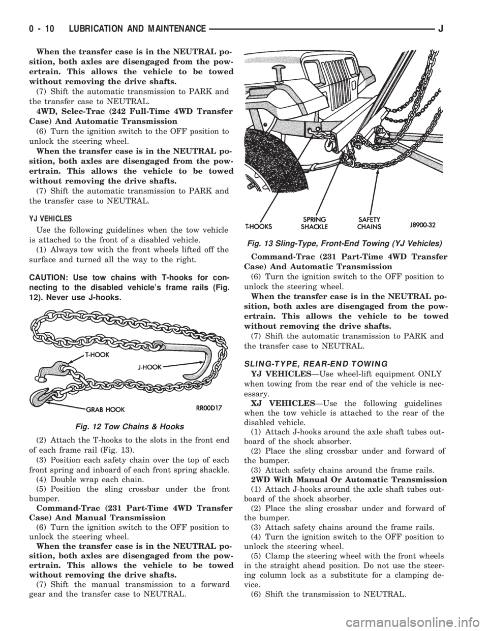
CAUTION: Use tow chains with T-hooks for con-
necting to the disabled vehicle's frame rails (Fig.
12). Never use J-hooks.
(2) Attach the T-hooks to the slots in the front end
of each frame rail (Fig. 13).
(3) Position each safety chain over the top of each
front spring and inboard of each front spring shackle.
(4) Double wrap each chain.
(5) Position the sling crossbar under the front
bumper.
Command-Trac (231 Part-Time 4WD Transfer
Case) And Manual Transmission
(6) Turn the ignition switch to the OFF position to
unlock the steering wheel.
When the transfer case is in the NEUTRAL po-
sition, both axles are disengaged from the pow-
ertrain. This allows the vehicle to be towed
without removing the drive shafts.
(7) Shift the manual transmission to a forward
gear and the transfer case to NEUTRAL.Command-Trac (231 Part-Time 4WD Transfer
Case) And Automatic Transmission
(6) Turn the ignition switch to the OFF position to
unlock the steering wheel.
When the transfer case is in the NEUTRAL po-
sition, both axles are disengaged from the pow-
ertrain. This allows the vehicle to be towed
without removing the drive shafts.
(7) Shift the automatic transmission to PARK and
the transfer case to NEUTRAL.
SLING-TYPE, REAR-END TOWING
YJ VEHICLESÐUse wheel-lift equipment ONLY
when towing from the rear end of the vehicle is nec-
essary.
XJ VEHICLESÐUse the following guidelines
when the tow vehicle is attached to the rear of the
disabled vehicle.
(1) Attach J-hooks around the axle shaft tubes out-
board of the shock absorber.
(2) Place the sling crossbar under and forward of
the bumper.
(3) Attach safety chains around the frame rails.
2WD With Manual Or Automatic Transmission
(1) Attach J-hooks around the axle shaft tubes out-
board of the shock absorber.
(2) Place the sling crossbar under and forward of
the bumper.
(3) Attach safety chains around the frame rails.
(4) Turn the ignition switch to the OFF position to
unlock the steering wheel.
(5) Clamp the steering wheel with the front wheels
in the straight ahead position. Do not use the steer-
ing column lock as a substitute for a clamping de-
vice.
(6) Shift the transmission to NEUTRAL.
Fig. 12 Tow Chains & Hooks
Fig. 13 Sling-Type, Front-End Towing (YJ Vehicles)
0 - 10 LUBRICATION AND MAINTENANCEJ
Page 12 of 1784
4WD, Command-Trac (231 Part-Time 4WD
Transfer Case) And Manual Transmission
(1) Attach J-hooks around the axle shaft tubes out-
board of the shock absorber.
(2) Place the sling crossbar under and forward of
the bumper.
(3) Attach safety chains around the frame rails.
(4) Turn the ignition switch to the OFF position to
unlock the steering column.
(5) Clamp the steering wheel with the front wheels
in the straight ahead position. Do not use the steer-
ing column lock as a substitute for a clamping de-
vice.
When the transfer case is in the NEUTRAL po-
sition, both axles are disengaged from the pow-
ertrain. This allows the vehicle to be towed
without removing the drive shafts.
(6) Shift the transmission to a forward gear and
the transfer case to NEUTRAL.
4WD, Command-Trac (231 Part-Time 4WD
Transfer Case) And Automatic Transmission
(1) Attach J-hooks around the axle shaft tubes out-
board of the shock absorber.
(2) Place the sling crossbar under and forward of
the bumper.
(3) Attach safety chains around the frame rails.
(4) Turn the ignition switch to the OFF position to
unlock the steering column.
(5) Clamp the steering wheel with the front wheels
in the straight ahead position. Do not use the steer-
ing column lock as a substitute for a clamping de-
vice.
When the transfer case is in the NEUTRAL po-
sition, both axles are disengaged from the pow-
ertrain. This allows the vehicle to be towed
without removing the drive shafts.
(6) Shift the transmission to PARK and the trans-
fer case to NEUTRAL.
4WD, Selec-Trac (242 Full-Time 4WD Transfer
Case) And Automatic Transmission
(1) Attach J-hooks around the axle shaft tubes out-
board of the shock absorber.
(2) Place the sling crossbar under and forward of
the bumper.
(3) Attach safety chains around the frame rails.
(4) Turn the ignition switch to the OFF position to
unlock the steering column.
(5) Clamp the steering wheel with the front wheels
in the straight ahead position. Do not use the steer-
ing column lock as a substitute for a clamping de-
vice.
When the transfer case is in the NEUTRAL po-
sition, both axles are disengaged from the pow-
ertrain. This allows the vehicle to be towed
without removing the drive shafts.
(6) Shift the transmission to PARK and the trans-
fer case to NEUTRAL.TOWING WHEN IGNITION KEYS ARE NOT
AVAILABLE
VEHICLE DOORS UNLOCKED
2WD Vehicles
Either one of two methods can be used:
²tow the vehicle with the drive shaft removed (refer
to Sling-Type, Front-End Towing); or
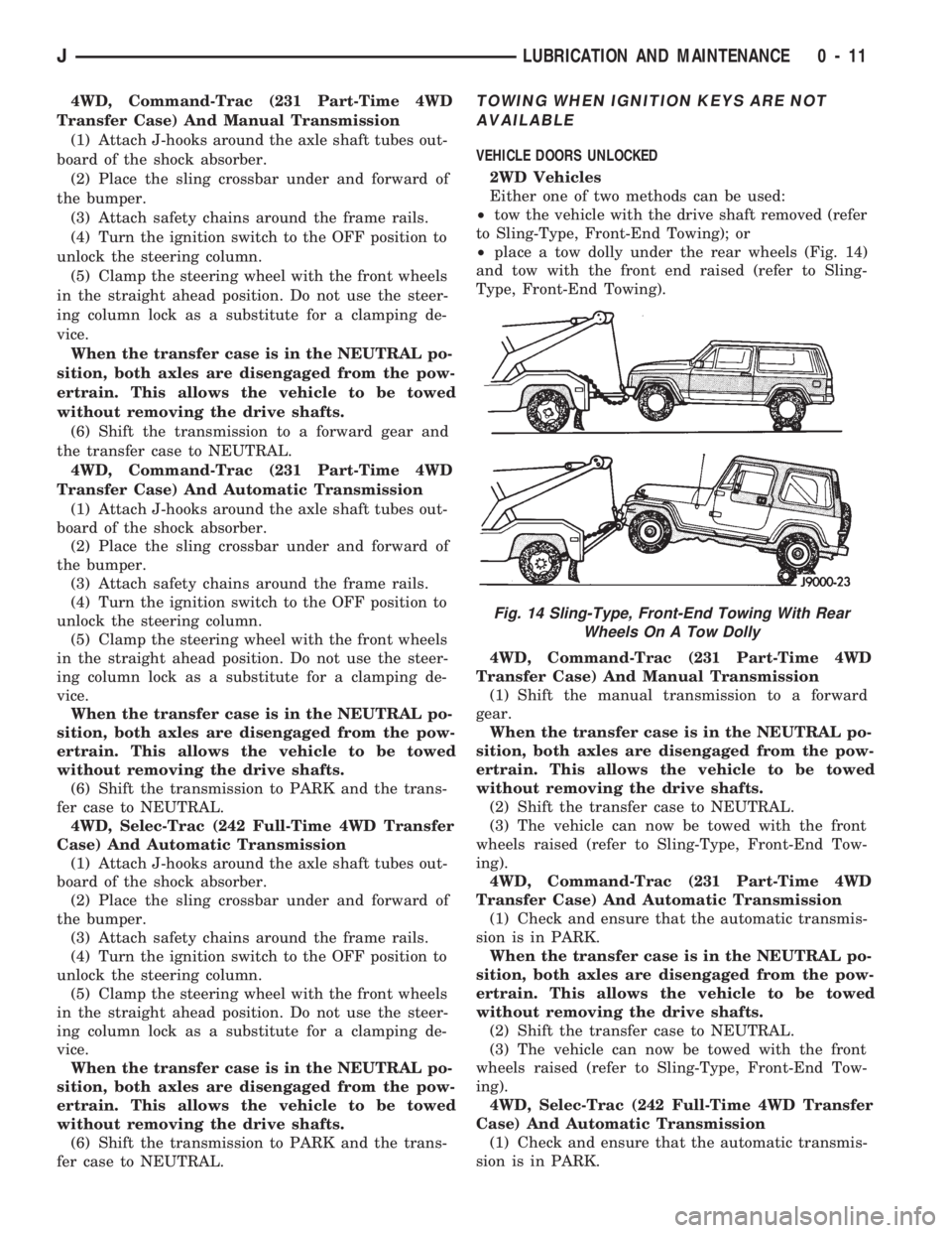
²place a tow dolly under the rear wheels (Fig. 14)
and tow with the front end raised (refer to Sling-
Type, Front-End Towing).
4WD, Command-Trac (231 Part-Time 4WD
Transfer Case) And Manual Transmission
(1) Shift the manual transmission to a forward
gear.
When the transfer case is in the NEUTRAL po-
sition, both axles are disengaged from the pow-
ertrain. This allows the vehicle to be towed
without removing the drive shafts.
(2) Shift the transfer case to NEUTRAL.
(3) The vehicle can now be towed with the front
wheels raised (refer to Sling-Type, Front-End Tow-
ing).
4WD, Command-Trac (231 Part-Time 4WD
Transfer Case) And Automatic Transmission
(1) Check and ensure that the automatic transmis-
sion is in PARK.
When the transfer case is in the NEUTRAL po-
sition, both axles are disengaged from the pow-
ertrain. This allows the vehicle to be towed
without removing the drive shafts.
(2) Shift the transfer case to NEUTRAL.
(3) The vehicle can now be towed with the front
wheels raised (refer to Sling-Type, Front-End Tow-
ing).
4WD, Selec-Trac (242 Full-Time 4WD Transfer
Case) And Automatic Transmission
(1) Check and ensure that the automatic transmis-
sion is in PARK.
Fig. 14 Sling-Type, Front-End Towing With Rear
Wheels On A Tow Dolly
JLUBRICATION AND MAINTENANCE 0 - 11
Page 13 of 1784
When the transfer case is in the NEUTRAL po-
sition, both axles are disengaged from the pow-
ertrain. This allows the vehicle to be towed
without removing the drive shafts.
(2) Shift the transfer case to NEUTRAL.
(3) The vehicle can now be towed with the front
wheels raised (refer to Sling-Type, Front-End Tow-
ing).
VEHICLE DOORS LOCKED
Place a tow dolly under the rear wheels (Fig. 14)
and tow with the front end raised (refer to Sling-
Type, Front-End Towing).
4WD EMERGENCY TOWINGÐTRANSFER CASE
NOT SHIFTED TO NEUTRAL
When a situation arises and the transfer case can-
not be shifted to NEUTRAL, any of the following
methods can be used to tow a 4WD vehicle.
Drive shafts not removed, place the rear
wheels on a tow dolly and tow with the front
end raised.
Drive shafts not removed, place the front
wheels on a tow dolly and tow with the rear end
raised.
Rear drive shaft removed, tow with the front
end raised.
Front drive shaft removed, tow with the rear
end raised.
Both drive shafts removed, tow with all four
wheels on the road surface.
(1) Turn ignition key switch to the unlocked (OFF)
position.
(2) Shift the transmission to the NEUTRAL posi-
tion.
(3) Determine the method by which the vehicle
will be towed and prepare the vehicle for towing.
(4) Connect the vehicle to the tow vehicle. Refer to
the applicable procedure.
FLAT TOWING (4 TIRES/WHEELS ON
SURFACE)
Tow a vehicle in this manner only when all four
wheels will freely rotate. Prepare the vehicle accord-
ing to the following procedures.
2WD VEHICLES
(1) Mark the drive shaft and the axle drive pinion
gear shaft yoke for installation alignment reference.
(2) Remove the drive shaft. Install a protective
covering over the drive shaft U-joints to retain them
assembled and protected.
(3) Cover the open end of the transmission exten-
sion housing.4WD VEHICLES
(1) Mark the drive shafts and the axle drive pinion
gear shaft yokes for installation alignment reference.
(2) Remove the drive shafts. Install a protective
covering over the drive shaft U-joints/CV-joints to re-
tain them assembled and protected.
(3) Cover the exposed ends of the transfer case.
CAUTION: Whenever a drive shaft has been re-
moved and installed, check the transmission fluid
level of the transmission and transfer case. Driving
a vehicle with low tranfer case fluid can damage the
transmission and transfer case.
EMERGENCY TOW HOOKS
WARNING: REMAIN AT A SAFE DISTANCE FROM A
VEHICLE THAT IS BEING TOWED VIA ITS TOW
HOOKS. THE TOW STRAPS/CHAINS COULD POSSI-
BLY BREAK AND CAUSE SERIOUS INJURY.
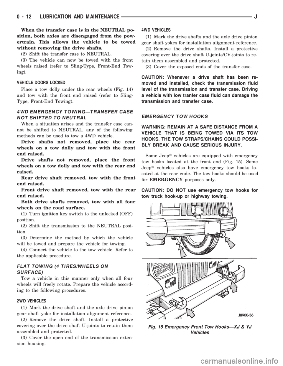
Some Jeeptvehicles are equipped with emergency
tow hooks located at the front end (Fig. 15). Some
Jeeptvehicles also have emergency tow hooks lo-
cated at the rear ende. The tow hooks should be used
forEMERGENCYpurposes only.
CAUTION: DO NOT use emergency tow hooks for
tow truck hook-up or highway towing.
Fig. 15 Emergency Front Tow HooksÐXJ & YJ
Vehicles
0 - 12 LUBRICATION AND MAINTENANCEJ
Page 21 of 1784
ENGINE SUPPORTS
RECOMMENDED MAINTENANCE
The general condition of the engine supports
should be inspected at the same time as the engine
oil is changed and the oil filter is replaced.
INSPECTION
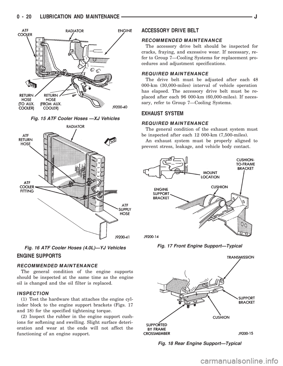
(1) Test the hardware that attaches the engine cyl-
inder block to the engine support brackets (Figs. 17
and 18) for the specified tightening torque.
(2) Inspect the rubber in the engine support cush-
ions for softening and swelling. Slight surface deteri-
oration and wear at the ends will not affect the
functioning of an engine support.
ACCESSORY DRIVE BELT
RECOMMENDED MAINTENANCE
The accessory drive belt should be inspected for
cracks, fraying, and excessive wear. If necessary, re-
fer to Group 7ÐCooling Systems for replacement pro-
cedures and adjustment specifications.
REQUIRED MAINTENANCE
The drive belt must be adjusted after each 48
000-km (30,000-miles) interval of vehicle operation
has elapsed. The accessory drive belt must be re-
placed after each 96 000-km (60,000-miles). If neces-
sary, refer to Group 7ÐCooling Systems.
EXHAUST SYSTEM
REQUIRED MAINTENANCE
The general condition of the exhaust system must
be inspected after each 12 000-km (7,500-miles).
An exhaust system must be properly aligned to
prevent stress, leakage, and vehicle body contact.
Fig. 17 Front Engine SupportÐTypical
Fig. 18 Rear Engine SupportÐTypical
Fig. 15 ATF Cooler Hoses ÐXJ Vehicles
Fig. 16 ATF Cooler Hoses (4.0L)ÐYJ Vehicles
0 - 20 LUBRICATION AND MAINTENANCEJ
Page 23 of 1784
DRIVETRAIN
INDEX
page page
Automatic Transmission.................... 23
Drive Shafts............................ 27
Front and Rear Axles..................... 26
Hydraulic Clutch......................... 22Manual Transmission...................... 22
Rubber and Plastic Hoses/Tubing............ 28
Transfer Case........................... 25
HYDRAULIC CLUTCH
RECOMMENDED MAINTENANCE
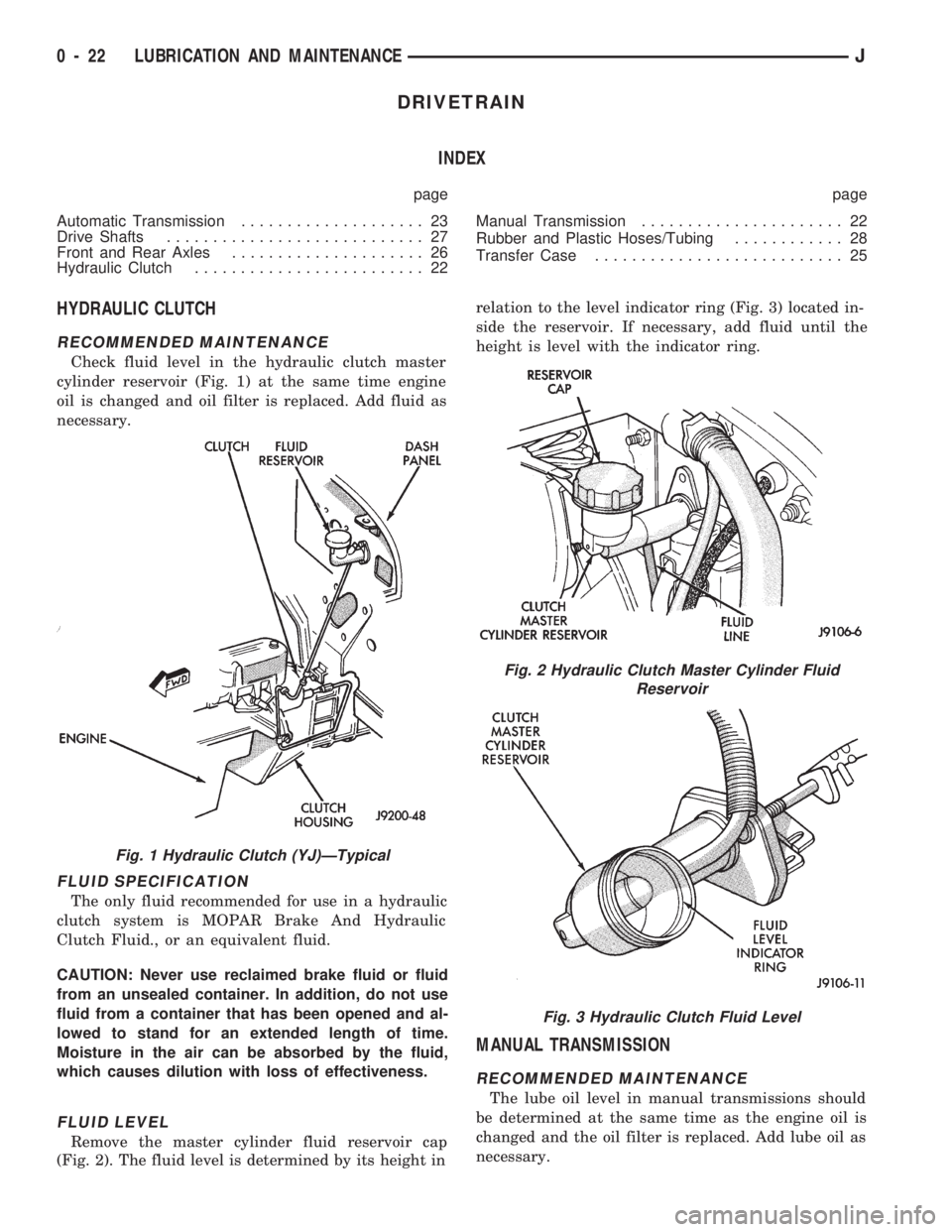
Check fluid level in the hydraulic clutch master
cylinder reservoir (Fig. 1) at the same time engine
oil is changed and oil filter is replaced. Add fluid as
necessary.
FLUID SPECIFICATION
The only fluid recommended for use in a hydraulic
clutch system is MOPAR Brake And Hydraulic
Clutch Fluid., or an equivalent fluid.
CAUTION: Never use reclaimed brake fluid or fluid
from an unsealed container. In addition, do not use
fluid from a container that has been opened and al-
lowed to stand for an extended length of time.
Moisture in the air can be absorbed by the fluid,
which causes dilution with loss of effectiveness.
FLUID LEVEL
Remove the master cylinder fluid reservoir cap
(Fig. 2). The fluid level is determined by its height inrelation to the level indicator ring (Fig. 3) located in-
side the reservoir. If necessary, add fluid until the
height is level with the indicator ring.
MANUAL TRANSMISSION
RECOMMENDED MAINTENANCE
The lube oil level in manual transmissions should
be determined at the same time as the engine oil is
changed and the oil filter is replaced. Add lube oil as
necessary.
Fig. 1 Hydraulic Clutch (YJ)ÐTypical
Fig. 2 Hydraulic Clutch Master Cylinder Fluid
Reservoir
Fig. 3 Hydraulic Clutch Fluid Level
0 - 22 LUBRICATION AND MAINTENANCEJ
Page 25 of 1784
dye to aid in detecting the source of ATF leaks. The
use of transmission sealing additives should also be
avoided.
Black-light detection dye is factory-installed in
automatic transmissions and, unless the ATF
has been drained and re-placed, it is not neces-
sary to add dye.
ATF LEVEL
Determine the ATF level according to the following
procedure.
WARNING: USE EXTREME CAUTION WHEN THE
ENGINE IS OPERATING. DO NOT PUT YOUR
HANDS NEAR THE DRIVE BELT, PULLEYS OR FAN
BLADE. DO NOT STAND IN A DIRECT LINE WITH
THE FAN BLADE.
(1) Operate the engine and allow the automatic
transmission sufficient time to warm to the normal
operating temperature (77ÉC/170ÉF).
When at normal operating temperature, ATF
will be uncomfortable to fingertips when the
dipstick is touched. Normally, 25 km (15 miles) is
a sufficient driving distance for a transmission
to warm to normal operating temperature (77ÉC/
170ÉF).
(2) Place the vehicle on a level surface.
(3) Operate the engine at idle speed.
(4) Engage the parking brake.
(5) Place a block in front of and at the rear of one
wheel/tire to prevent vehicle movement.
(6) Depress the brake pedal and move the trans-
mission selector lever through all the positions and
then place the selector lever in NEUTRAL position.
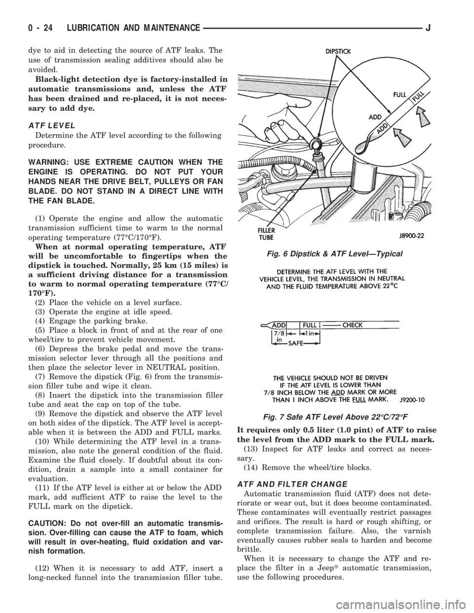
(7) Remove the dipstick (Fig. 6) from the transmis-
sion filler tube and wipe it clean.
(8) Insert the dipstick into the transmission filler
tube and seat the cap on top of the tube.
(9) Remove the dipstick and observe the ATF level
on both sides of the dipstick. The ATF level is accept-
able when it is between the ADD and FULL marks.
(10) While determining the ATF level in a trans-
mission, also note the general condition of the fluid.
Examine the fluid closely. If doubtful about its con-
dition, drain a sample into a small container for
evaluation.
(11) If the ATF level is either at or below the ADD
mark, add sufficient ATF to raise the level to the
FULL mark on the dipstick.
CAUTION: Do not over-fill an automatic transmis-
sion. Over-filling can cause the ATF to foam, which
will result in over-heating, fluid oxidation and var-
nish formation.
(12) When it is necessary to add ATF, insert a
long-necked funnel into the transmission filler tube.It requires only 0.5 liter (1.0 pint) of ATF to raise
the level from the ADD mark to the FULL mark.
(13) Inspect for ATF leaks and correct as neces-
sary.
(14) Remove the wheel/tire blocks.
ATF AND FILTER CHANGE
Automatic transmission fluid (ATF) does not dete-
riorate or wear out, but it does become contaminated.
These contaminates will eventually restrict passages
and orifices. The result is hard or rough shifting, or
complete transmission failure. Also, the varnish
eventually causes rubber seals to harden and become
brittle.
When it is necessary to change the ATF and re-
place the filter in a Jeeptautomatic transmission,
use the following procedures.
Fig. 6 Dipstick & ATF LevelÐTypical
Fig. 7 Safe ATF Level Above 22ÉC/72ÉF
0 - 24 LUBRICATION AND MAINTENANCEJ
Page 26 of 1784
DRAINING ATF/FILTER REMOVAL
Drain the automatic transmission fluid (ATF) im-
mediately after stopping the engine (before the ATF
cools).
(1) Raise and support the vehicle.
(2) Loosen the transmission pan bolts and drain
the original ATF into an appropriate container. Re-
move the pan bolts, the pan and the gasket.
Care should be exercised when disposing used
ATF after it has been drained from a vehicle
transmission.
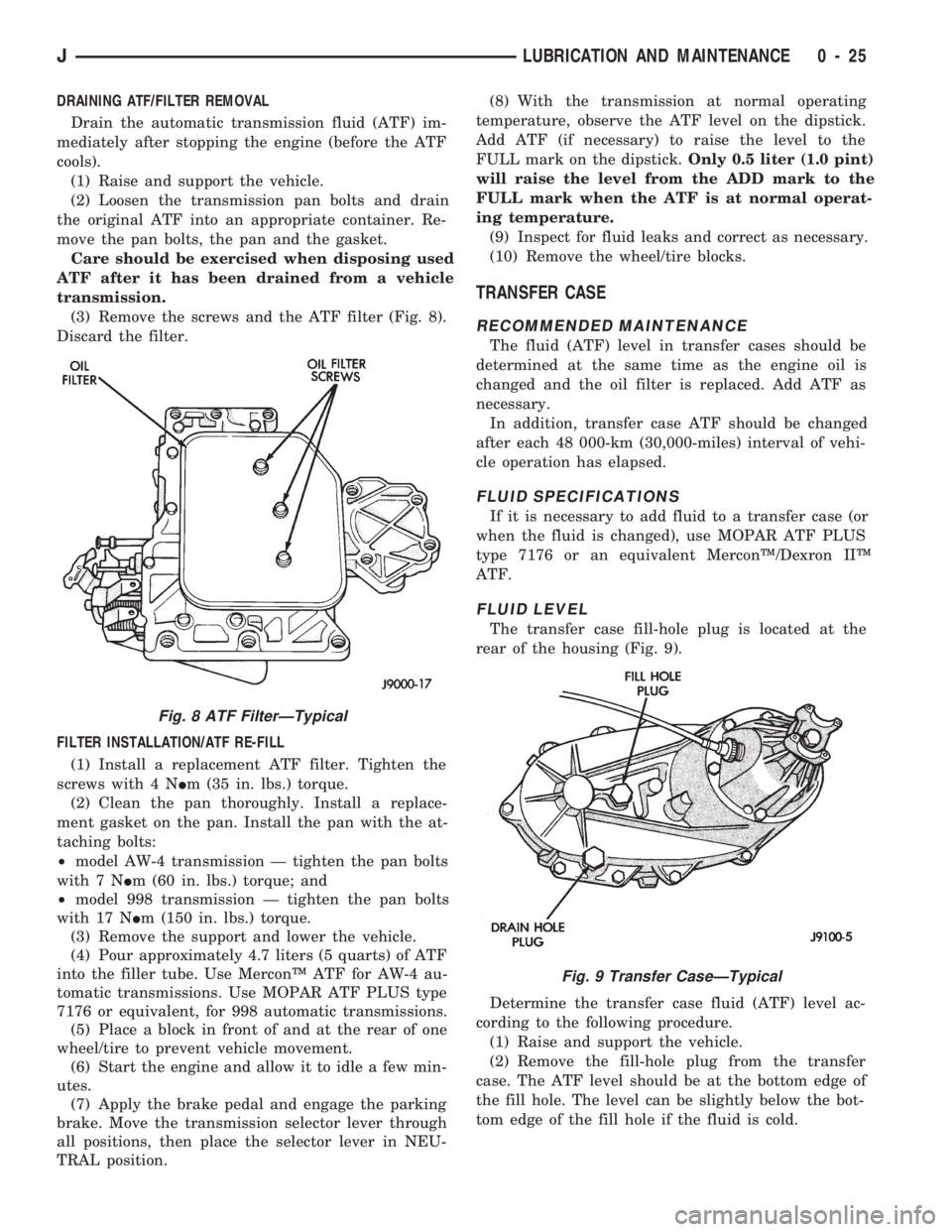
(3) Remove the screws and the ATF filter (Fig. 8).
Discard the filter.
FILTER INSTALLATION/ATF RE-FILL
(1) Install a replacement ATF filter. Tighten the
screws with 4 NIm (35 in. lbs.) torque.
(2) Clean the pan thoroughly. Install a replace-
ment gasket on the pan. Install the pan with the at-
taching bolts:
²model AW-4 transmission Ð tighten the pan bolts
with 7 NIm (60 in. lbs.) torque; and
²model 998 transmission Ð tighten the pan bolts
with 17 NIm (150 in. lbs.) torque.
(3) Remove the support and lower the vehicle.
(4) Pour approximately 4.7 liters (5 quarts) of ATF
into the filler tube. Use MerconŸ ATF for AW-4 au-
tomatic transmissions. Use MOPAR ATF PLUS type
7176 or equivalent, for 998 automatic transmissions.
(5) Place a block in front of and at the rear of one
wheel/tire to prevent vehicle movement.
(6) Start the engine and allow it to idle a few min-
utes.
(7) Apply the brake pedal and engage the parking
brake. Move the transmission selector lever through
all positions, then place the selector lever in NEU-
TRAL position.(8) With the transmission at normal operating
temperature, observe the ATF level on the dipstick.
Add ATF (if necessary) to raise the level to the
FULL mark on the dipstick.Only 0.5 liter (1.0 pint)
will raise the level from the ADD mark to the
FULL mark when the ATF is at normal operat-
ing temperature.
(9) Inspect for fluid leaks and correct as necessary.
(10) Remove the wheel/tire blocks.
TRANSFER CASE
RECOMMENDED MAINTENANCE
The fluid (ATF) level in transfer cases should be
determined at the same time as the engine oil is
changed and the oil filter is replaced. Add ATF as
necessary.
In addition, transfer case ATF should be changed
after each 48 000-km (30,000-miles) interval of vehi-
cle operation has elapsed.
FLUID SPECIFICATIONS
If it is necessary to add fluid to a transfer case (or
when the fluid is changed), use MOPAR ATF PLUS
type 7176 or an equivalent MerconŸ/Dexron IIŸ
ATF.
FLUID LEVEL
The transfer case fill-hole plug is located at the
rear of the housing (Fig. 9).
Determine the transfer case fluid (ATF) level ac-
cording to the following procedure.
(1) Raise and support the vehicle.
(2) Remove the fill-hole plug from the transfer
case. The ATF level should be at the bottom edge of
the fill hole. The level can be slightly below the bot-
tom edge of the fill hole if the fluid is cold.
Fig. 9 Transfer CaseÐTypical
Fig. 8 ATF FilterÐTypical
JLUBRICATION AND MAINTENANCE 0 - 25