high beam JEEP CHEROKEE 1994 Service Repair Manual
[x] Cancel search | Manufacturer: JEEP, Model Year: 1994, Model line: CHEROKEE, Model: JEEP CHEROKEE 1994Pages: 1784, PDF Size: 77.09 MB
Page 361 of 1784
INSTRUMENT PANEL AND GAUGESÐYJE
CONTENTS
page page
GAUGE PACKAGE DIAGNOSIS............ 22
GAUGE PACKAGE GENERAL INFORMATION . 22
GAUGE PACKAGE SERVICE PROCEDURES . . 24
INSTRUMENT CLUSTER DIAGNOSIS....... 14INSTRUMENT CLUSTER GENERAL INFORMATION.14
INSTRUMENT CLUSTER SERVICE PROCEDURES.. 17
SPECIFICATIONS....................... 27
INSTRUMENT CLUSTER GENERAL INFORMATION
SPEEDOMETER/ODOMETER SYSTEM
The speedometer/odometer system consists of an
electric speedometer and pushbutton reset odometer
mounted in the cluster. The system also includes the
wire harness from the cluster to the vehicle speed
sensor at the transmission, and the adapter and pin-
ion in the transmission. A signal is sent from a
transmission mounted vehicle speed sensor to the
speedometer/odometer circuitry through the wiring
harness. Refer to Group 21 - Transmission for select-
ing the proper pinion, and selecting and indexing the
proper adapter.
TACHOMETER
The tachometer displays the engine speed (RPM).
With the engine running, the tachometer receives anengine speed signal from the Powertrain Control
Module pin 43 (values shown in Specifications chart).
INDICATOR LAMPS
The Brake, Upshift (2.5L with 5 speed transmis-
sion except California), and Malfunction Indicator
(Check Engine) lamps are located in the indicator
lamp panel above the steering column. The lamps
share a common battery feed connection through the
ignition switch and fuse #9.
The turn signals, high beam indicator, seat belt re-
minder, hazard lamp, master lighting and illumina-
tion bulbs are supplied battery voltage through
various switches and share a common ground.
INSTRUMENT CLUSTER DIAGNOSIS
INDEX
page page
Brake Indicator Lamp...................... 16
DiagnosingÐAll Lamps Out................. 16
Instrument Panel Illumination Lamps.......... 16
Malfunction Indicator Lamp (Check Engine)..... 16Seat Belt Reminder Lamp................... 16
Speedometer............................ 14
Tachometer............................. 14
Upshift Indicator Lamp..................... 16
SPEEDOMETER
(1) Raise vehicle.
(2) Disconnect the vehicle speed sensor connector.
(3) Connect a voltmeter between the black wire
pin of the connector and ground.
(4) Turn the ignition switch to the ON position.
(5) Check for approximately 5 volts. If OK, per-
form vehicle speed sensor test. Refer to the appropri-
ate Powertrain Diagnostic Procedures manual. If not
OK, continue with step 6.
(6) Turn ignition switch to OFF position.(7) Check continuity between vehicle speed sensor
connector and terminal 13 of instrument cluster con-
nector. If OK, replace speedometer. If not OK, repair
open circuit.
TACHOMETER
(1) Tachometer input is from the Powertrain Con-
trol Module (PCM) pin 43. Use the DRB scan tool to
perform actuator test. If OK, continue with step 2. If
not, replace PCM.
(2) Check for continuity between cluster connector
pin 12 and PCM pin 43. If OK, replace tachometer. If
not, repair open circuit.
8E - 14 YJ INSTRUMENT PANEL AND GAUGESJ
Page 428 of 1784
LAMPS
CONTENTS
page page
EXTERIOR LAMPS....................... 1
INTERIOR LAMPS...................... 19SPECIFICATIONS....................... 23
EXTERIOR LAMPS
INDEX
page page
Back-up/Rear Turn Signal/Tail Lamp Bulb
Replacement........................... 9
Center High Mounted Stop Lamp (CHMSL)ÐXJ . 10
Center High Mounted Stop Lamp (CHMSL)ÐYJ . 11
Daytime Running Lights (Canada Only)........ 16
DRL Module Replacement.................. 16
Fog Lamp Beam Adjustment................ 12
Fog Lamp Bulb/Element Replacement......... 13
Fog Lamp Replacement................... 15
Fog Lamp Service Information............... 12
Fog Lamp Switch Replacement.............. 14
Fog Lamp Trouble Diagnosis................ 12
Front Park/Turn Signal Lamp Bulb Replacement . . 8
Headlamp Beam Adjustment................. 3
Headlamp Bulb Replacement................ 3
Headlamp Delay Function Trouble DiagnosisÐXJ
Vehicles.............................. 16Headlamp Delay Module ReplacementÐXJ
Vehicles.............................. 16
Headlamp Dimmer Switch Replacement........ 6
Headlamp Switch Replacement............... 4
Headlamp Trouble DiagnosisÐXJ Vehicles...... 1
Headlamp Trouble DiagnosisÐYJ Vehicles...... 2
License Plate Lamp....................... 10
Sentinel Headlamp Delay ModuleÐXJ Vehicles . . 15
Service Information........................ 1
Side Marker Lamp Bulb Replacement.......... 7
Switch Tests............................. 2
Underhood Lamp Bulb Replacement.......... 18
Underhood Lamp Replacement.............. 18
Underhood Lamp Service Information......... 17
SERVICE INFORMATION
Exterior lamp circuits are comprised of the head-
lamp circuit, fog lamp circuit, and tail/side marker/
park lamp circuit. Battery voltage is controlled by
both the headlamp ON/OFF switch and headlamp
dimmer switch.
The dimmer switch functions as a fog lamp switch.
Voltage is applied to the fog lamp switch only when
the dimmer switch is in the low beam position.
HEADLAMP TROUBLE DIAGNOSISÐXJ VEHICLES
LOW AND HIGH BEAM INOPERATIVE BOTH
HEADLAMPS
(1) Place the headlamp switch in the ON position.
(2) Test the 40 amp fuse for continuity. If bad, re-
place fuse.
(3) Insert the test probe into terminal 5 of the
front lamp wire harness connector. Measure the re-
sistance from terminal 5 to body ground. The ohm-
meter should indicate zero ohms. If not OK, repair
the open circuit in the harness to body ground.(4) Disconnect the front lamp wire connector. Mea-
sure resistance between connector terminals 5 and 2.
Next measure between terminal 5 and 7. The ohm-
meter should indicate zero ohms for both measure-
ments. If not OK, replace the headlamp bulbs.
(5) Measure the voltage between the dimmer
switch wire connector terminal 2 and body ground.
The voltmeter should indicate battery voltage. If not
OK, continue with the next step.
The dimmer switch is integral with the turn
signal and is located on the steering column.
The dimmer switch switches the headlamp beam
when the turn signal lever is pulled rearward.
(6) Disconnect the dimmer switch wire connector
and place the headlamp switch in the OFF position.
Measure the resistance from terminal 2 to vehicle
body ground. The ohmmeter should indicate infinite
resistance. If OK, replace the headlamp switch and
continue with the next step. If not OK, repair the
short circuit in the wire harness that leads to termi-
nal 2.
JLAMPS 8L - 1
Page 429 of 1784
(7) Measure the resistance from the dimmer switch
wire harness connector terminal 1 to vehicle body
ground. The ohmmeter should indicate zero ohms. If
OK, continue with the next step. If not OK, repair
the short circuit in the wire harness that leads to
terminal 1.
(8) Measure the resistance from the dimmer switch
wire harness connector terminal 3 to vehicle body
ground. The ohmmeter should indicate zero ohms. If
OK, test the dimmer switch. Replace, if defective.
Connect the wire harness connector to the dimmer
switch. If not defective, repair the short circuit in the
wire harness that leads to terminal 3.
LOW OR HIGH BEAM INOPERATIVE BOTH
HEADLAMPS
(1) Place the headlamp switch in the OFF position.
Disconnect the dimmer switch wire harness connec-
tor.
(2) Measure the resistance from the dimmer switch
connector terminal 1 to body ground. The ohmmeter
should indicate zero ohms. If not OK, repair the open
circuit in the wire harness that leads to the head-
lamp bulbs.
(3) Measure the resistance from the dimmer switch
connector terminal 3 to vehicle body ground. The
ohmmeter should indicate zero ohms. If OK, replace
the dimmer switch. If not OK, repair the open circuit
in the wire harness that leads to headlamp bulbs.
HEADLAMP TROUBLE DIAGNOSISÐYJ VEHICLES
(1) Place the headlamp switch in the ON position.
(2) Place the headlamp dimmer switch in the
HIGH or LOW position.
(3) Disconnect the wire harness connectors from
the headlamp bulbs.
(4) If applicable, measure voltage between each
headlamp bulb wire connector terminal B and vehi-
cle body ground. The voltmeter should indicate bat-
tery voltage. If not OK, repair the open circuit in
wire harness between connector and dimmer switch.
(5) If applicable, measure the voltage between each
headlamp bulb connector terminal C and body
ground. The voltmeter should indicate battery volt-
age. If not OK, repair the open circuit in the wire
harness between the connector and the dimmer
switch.
(6) Measure the resistance from each headlamp
bulb connector terminal A to body ground. The ohm-
meter should indicate zero ohms. If not OK, repair
the open circuit in the wire harness between the con-
nectors and vehicle body ground.
SWITCH TESTS
HEADLAMPÐALL VEHICLES
(1) Refer to the applicable wiring diagram for ter-
minal reference.(2) Place the headlamp switch in the ON position.
(3) Measure the voltage between the headlamp
switch connector voltage supply terminal and vehicle
body ground. The voltmeter should indicate battery
voltage. If not OK, repair the open circuit in the wire
harness between the fuse and the switch connector
terminal.
(4) Measure the voltage between the headlamp
switch connector battery voltage OUT terminal and
vehicle body ground. The voltmeter should indicate
battery voltage. If not OK, replace the headlamp
switch.
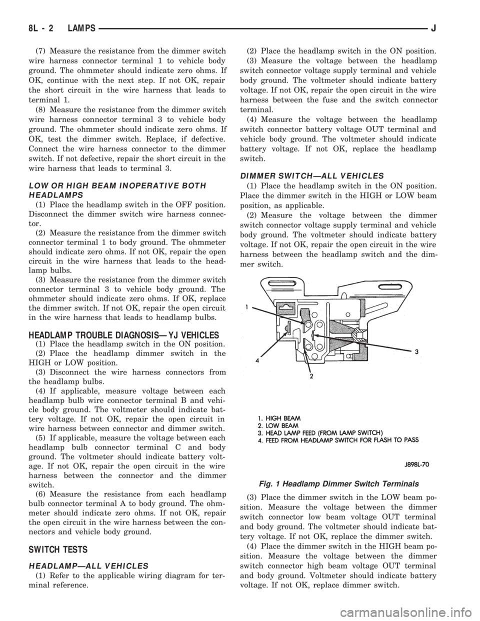
DIMMER SWITCHÐALL VEHICLES
(1) Place the headlamp switch in the ON position.
Place the dimmer switch in the HIGH or LOW beam
position, as applicable.
(2) Measure the voltage between the dimmer
switch connector voltage supply terminal and vehicle
body ground. The voltmeter should indicate battery
voltage. If not OK, repair the open circuit in the wire
harness between the headlamp switch and the dim-
mer switch.
(3) Place the dimmer switch in the LOW beam po-
sition. Measure the voltage between the dimmer
switch connector low beam voltage OUT terminal
and body ground. The voltmeter should indicate bat-
tery voltage. If not OK, replace the dimmer switch.
(4) Place the dimmer switch in the HIGH beam po-
sition. Measure the voltage between the dimmer
switch connector high beam voltage OUT terminal
and body ground. Voltmeter should indicate battery
voltage. If not OK, replace dimmer switch.
Fig. 1 Headlamp Dimmer Switch Terminals
8L - 2 LAMPSJ
Page 439 of 1784
FOG LAMP SERVICE INFORMATION
Fog lamps can be operatedONLYwhen the head-
lamps are on LOW beam. If the headlamps are
switched to HIGH beam, the fog lamps will not oper-
ate.
Also, the fog lamps ON display on the switch will:
²be illuminated when the headlamps are switched
to LOW beam; and
²be extinguished when the headlamps are switched
to HIGH beam.
FOG LAMP TROUBLE DIAGNOSIS
ONE FOG LAMP INOPERATIVE
(1) Place the headlamp switch in the full ON posi-
tion, the dimmer switch in the LOW beam position
and the fog lamp switch in the ON position.
(2) Disconnect the applicable fog lamp wire har-
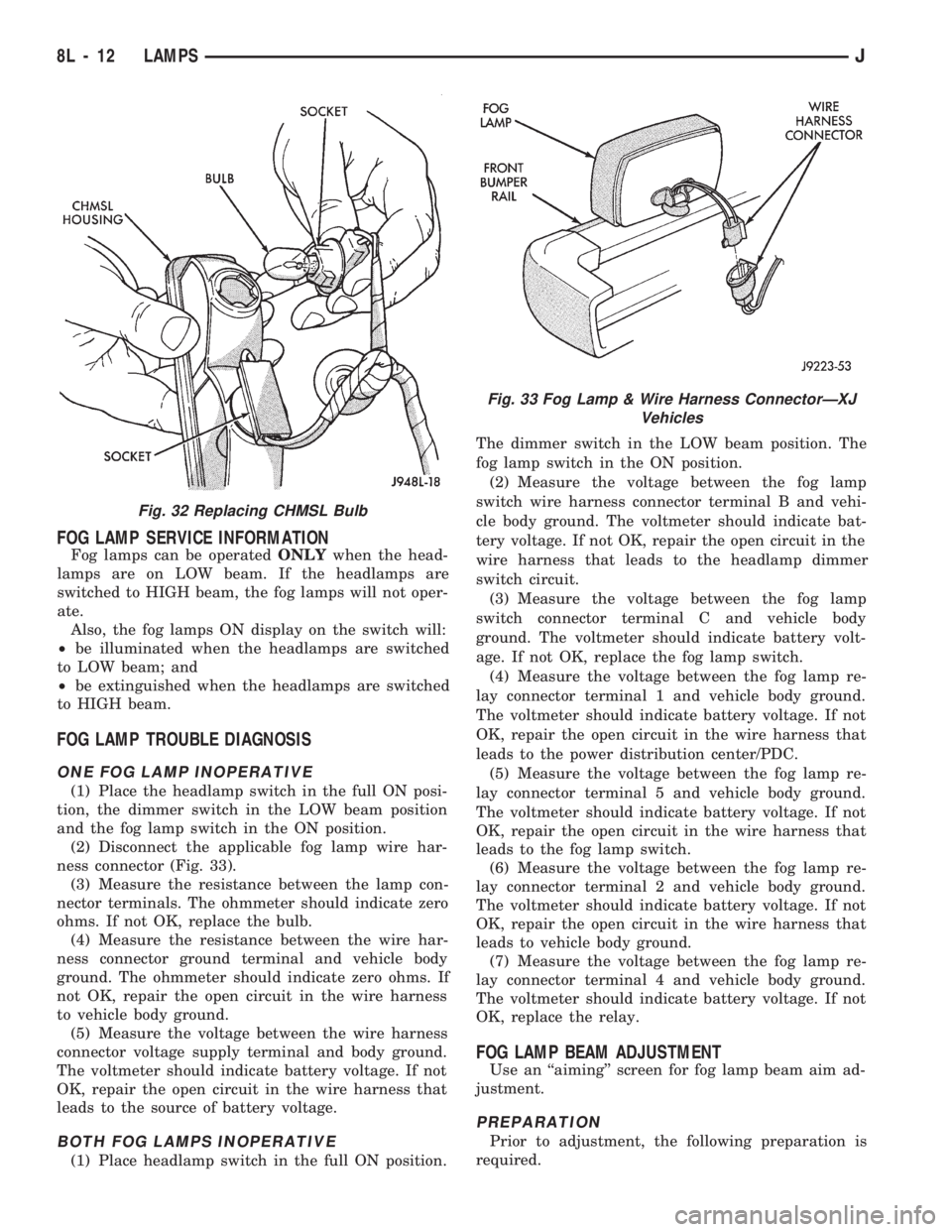
ness connector (Fig. 33).
(3) Measure the resistance between the lamp con-
nector terminals. The ohmmeter should indicate zero
ohms. If not OK, replace the bulb.
(4) Measure the resistance between the wire har-
ness connector ground terminal and vehicle body
ground. The ohmmeter should indicate zero ohms. If
not OK, repair the open circuit in the wire harness
to vehicle body ground.
(5) Measure the voltage between the wire harness
connector voltage supply terminal and body ground.
The voltmeter should indicate battery voltage. If not
OK, repair the open circuit in the wire harness that
leads to the source of battery voltage.
BOTH FOG LAMPS INOPERATIVE
(1) Place headlamp switch in the full ON position.The dimmer switch in the LOW beam position. The
fog lamp switch in the ON position.
(2) Measure the voltage between the fog lamp
switch wire harness connector terminal B and vehi-
cle body ground. The voltmeter should indicate bat-
tery voltage. If not OK, repair the open circuit in the
wire harness that leads to the headlamp dimmer
switch circuit.
(3) Measure the voltage between the fog lamp
switch connector terminal C and vehicle body
ground. The voltmeter should indicate battery volt-
age. If not OK, replace the fog lamp switch.
(4) Measure the voltage between the fog lamp re-
lay connector terminal 1 and vehicle body ground.
The voltmeter should indicate battery voltage. If not
OK, repair the open circuit in the wire harness that
leads to the power distribution center/PDC.
(5) Measure the voltage between the fog lamp re-
lay connector terminal 5 and vehicle body ground.
The voltmeter should indicate battery voltage. If not
OK, repair the open circuit in the wire harness that
leads to the fog lamp switch.
(6) Measure the voltage between the fog lamp re-
lay connector terminal 2 and vehicle body ground.
The voltmeter should indicate battery voltage. If not
OK, repair the open circuit in the wire harness that
leads to vehicle body ground.
(7) Measure the voltage between the fog lamp re-
lay connector terminal 4 and vehicle body ground.
The voltmeter should indicate battery voltage. If not
OK, replace the relay.
FOG LAMP BEAM ADJUSTMENT
Use an ``aiming'' screen for fog lamp beam aim ad-
justment.
PREPARATION
Prior to adjustment, the following preparation is
required.
Fig. 32 Replacing CHMSL Bulb
Fig. 33 Fog Lamp & Wire Harness ConnectorÐXJ
Vehicles
8L - 12 LAMPSJ
Page 643 of 1784
Wiring Diagram Name Sheet Number
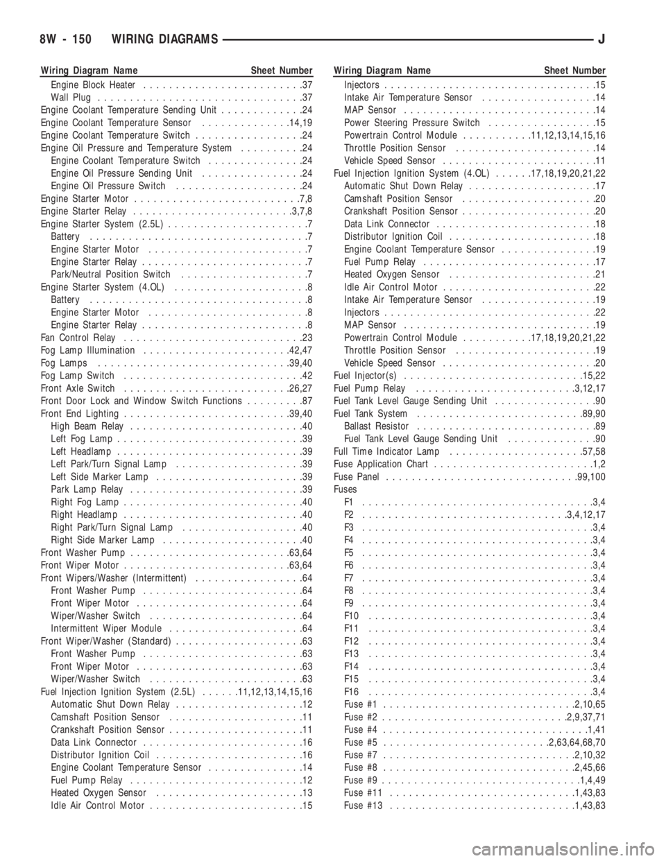
Engine Block Heater.........................37
Wall Plug................................37
Engine Coolant Temperature Sending Unit.............24
Engine Coolant Temperature Sensor..............14,19
Engine Coolant Temperature Switch.................24
Engine Oil Pressure and Temperature System..........24
Engine Coolant Temperature Switch...............24
Engine Oil Pressure Sending Unit................24
Engine Oil Pressure Switch....................24
Engine Starter Motor..........................7,8
Engine Starter Relay.........................3,7,8
Engine Starter System (2.5L)......................7
Battery..................................7
Engine Starter Motor.........................7
Engine Starter Relay..........................7
Park/Neutral Position Switch....................7
Engine Starter System (4.OL).....................8
Battery..................................8
Engine Starter Motor.........................8
Engine Starter Relay..........................8
Fan Control Relay............................23
Fog Lamp Illumination.......................42,47
Fog Lamps..............................39,40
Fog Lamp Switch............................42
Front Axle Switch..........................26,27
Front Door Lock and Window Switch Functions.........87
Front End Lighting..........................39,40
High Beam Relay...........................40
Left Fog Lamp.............................39
Left Headlamp.............................39
Left Park/Turn Signal Lamp....................39
Left Side Marker Lamp.......................39
Park Lamp Relay...........................39
Right Fog Lamp............................40
Right Headlamp............................40
Right Park/Turn Signal Lamp...................40
Right Side Marker Lamp......................40
Front Washer Pump.........................63,64
Front Wiper Motor..........................63,64
Front Wipers/Washer (Intermittent).................64
Front Washer Pump.........................64
Front Wiper Motor..........................64
Wiper/Washer Switch........................64
Intermittent Wiper Module.....................64
Front Wiper/Washer (Standard)....................63
Front Washer Pump.........................63
Front Wiper Motor..........................63
Wiper/Washer Switch........................63
Fuel Injection Ignition System (2.5L)......11,12,13,14,15,16
Automatic Shut Down Relay....................12
Camshaft Position Sensor.....................11
Crankshaft Position Sensor.....................11
Data Link Connector.........................16
Distributor Ignition Coil.......................16
Engine Coolant Temperature Sensor...............14
Fuel Pump Relay...........................12
Heated Oxygen Sensor.......................13
Idle Air Control Motor........................15Wiring Diagram Name Sheet Number
Injectors.................................15
Intake Air Temperature Sensor..................14
MAP Sensor..............................14
Power Steering Pressure Switch.................15
Powertrain Control Module...........11,12,13,14,15,16
Throttle Position Sensor......................14
Vehicle Speed Sensor........................11
Fuel Injection Ignition System (4.OL)......17,18,19,20,21,22
Automatic Shut Down Relay....................17
Camshaft Position Sensor.....................20
Crankshaft Position Sensor.....................20
Data Link Connector.........................18
Distributor Ignition Coil.......................18
Engine Coolant Temperature Sensor...............19
Fuel Pump Relay...........................17
Heated Oxygen Sensor.......................21
Idle Air Control Motor........................22
Intake Air Temperature Sensor..................19
Injectors.................................22
MAP Sensor..............................19
Powertrain Control Module...........17,18,19,20,21,22
Throttle Position Sensor......................19
Vehicle Speed Sensor........................20
Fuel Injector(s)............................15,22
Fuel Pump Relay.........................3,12,17
Fuel Tank Level Gauge Sending Unit................90
Fuel Tank System..........................89,90
Ballast Resistor............................89
Fuel Tank Level Gauge Sending Unit..............90
Full Time Indicator Lamp.....................57,58
Fuse Application Chart.........................1,2
Fuse Panel..............................99,100
Fuses
F1 ....................................3,4
F2 ................................3,4,12,17
F3 ....................................3,4
F4 ....................................3,4
F5 ....................................3,4
F6 ....................................3,4
F7 ....................................3,4
F8 ....................................3,4
F9 ....................................3,4
F10 ...................................3,4
F11 ...................................3,4
F12 ...................................3,4
F13 ...................................3,4
F14 ...................................3,4
F15 ...................................3,4
F16 ...................................3,4
Fuse #1..............................2,10,65
Fuse #2.............................2,9,37,71
Fuse #4................................1,41
Fuse #5..........................2,63,64,68,70
Fuse #7..............................2,10,32
Fuse #8..............................2,45,66
Fuse #9...............................1,4,49
Fuse #11.............................1,43,83
Fuse #13.............................1,43,83
8W - 150 WIRING DIAGRAMSJ
Page 644 of 1784
Wiring Diagram Name Sheet Number
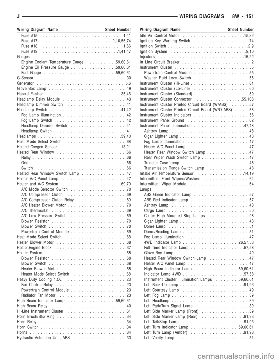
Fuse #15...............................1,41
Fuse #17...........................2,10,55,74
Fuse #18...............................1,66
Fuse #19.............................1,41,47
Gauges
Engine Coolant Temperature Gauge...........59,60,61
Engine Oil Pressure Gauge.................59,60,61
Fuel Gauge...........................59,60,61
G Sensor..................................30
Generator.................................5,6
Glove Box Lamp.............................49
Hazard Flasher............................35,46
Headlamp Delay Module........................43
Headlamp Dimmer Switch.......................41
Headlamp Switch...........................41,42
Fog Lamp Illumination........................42
Fog Lamp Switch...........................42
Headlamp Dimmer Switch.....................41
Headlamp Switch...........................41
Headlamps...............................39,40
Heat Mode Select Switch.......................68
Heated Oxygen Sensor.......................13,21
Heated Rear Window..........................66
Relay...................................66
Grid...................................66
Switch..................................66
Heated Rear Window Switch Lamp.................47
Heater A/C Panel Lamp........................47
Heater and A/C System......................69,70
A/C Mode Selector Switch.....................70
A/C Compressor Clutch.......................69
A/C Compressor Clutch Relay...................69
A/C Heater Blower Motor......................70
A/C Thermostat............................69
A/C Low Pressure Switch.....................69
Blower Resistor............................70
Blower Switch.............................70
Powertrain Control Module.....................69
Heat Mode Select Switch.......................68
Heater Blower Motor..........................68
Heater,Engine Block...........................37
Heater System..............................68
Blower Resistor............................68
Blower Switch.............................68
Heater Blower Motor.........................68
Heater Mode Select Switch....................68
Heavy Duty Cooling 4.OL.......................23
Fan Control Relay...........................23
Powertrain Control Module.....................23
Radiator Fan Motor.........................23
High Beam Indicator Lamp..................59,60,61
High Beam Relay............................40
Hi-Line Instrument Cluster.......................61
Horn Brush/Slip Ring..........................34
Horn Relay................................34
Horn Switch................................34
Horns....................................34
Hydraulic Actuation Unit, ABS....................33Wiring Diagram Name Sheet Number
Idle Air Control Motor.......................15,22
Ignition Key Warning Switch.....................74
Ignition Switch..............................2,9
Ignition System............................9,10
Injectors................................15,22
In Line Circuit Breaker..........................2
Instrument Cluster............................55
Powertrain Control Module.....................55
Washer Fluid Level Switch.....................55
Instrument Cluster (Hi-Line)......................61
Instrument Cluster (Lo-Line).....................60
Instrument Cluster (Standard)....................59
Instrument Cluster Connector..................55,108
Instrument Cluster Printed Circuit Board (W/ABS).......57
Instrument Cluster Printed Circuit Board (W/O ABS)......58
Instrument Cluster Indicators.....................56
Instrument Panel Ground.......................62
Instrument Panel Illumination...................47,48
Ashtray Lamp.............................48
Cigar Lighter Lamp..........................48
Fog Lamp Illumination........................47
Heater A/C Panel Lamp.......................47
Heater Rear Window Switch Lamp................47
Rear Wiper Wash Switch Lamp..................47
Transfer Case Lamp.........................48
Transmission Range Switch Lamp................48
Intake Air Temperature Sensor..................14,19
Intermittent Front Wipers/Washers.................64
Intermittent Wiper Module.......................64
Lamps
ABS Green Indicator Lamp.....................57
ABS Red Indicator Lamp......................57
Ashtray Lamp.............................48
Cargo Lamp..............................50
Center High Mounted Stop Lamps................98
Cigar Lighter Lamp..........................48
Dome Lamp..............................51
Dome/Reading Lamp.........................51
Fog Lamp Illumination........................47
4WD Indicator Lamp.....................26,57,58
Full Time Indicator Lamp....................57,58
Glove Box Lamp...........................49
Heated Rear Window Switch Lamp...............47
Heater A/C Panel Lamp.......................47
High Beam Indicator Lamp.................59,60,61
Indicator Lamp 4WD.......................57,58
Instrument Cluster Illumination Lamps.........59,60,61
Left Back-Up Lamp........................91,93
Left Courtesy Lamp.........................49
Left Fog Lamp.............................39
Left Headlamp.............................39
Left Park/Turn Signal Lamp....................39
Left Side Marker Lamp (Front)..................39
Left Side Marker Lamp (Rear)................91,93
Left Tail/Stop Lamp.......................91,93
Left Turn Indicator Lamp..................59,60,61
Left Turn Lamp (Amber)....................91,93
Left Vanity Lamp...........................51
JWIRING DIAGRAMS 8W - 151
Page 646 of 1784
Wiring Diagram Name Sheet Number
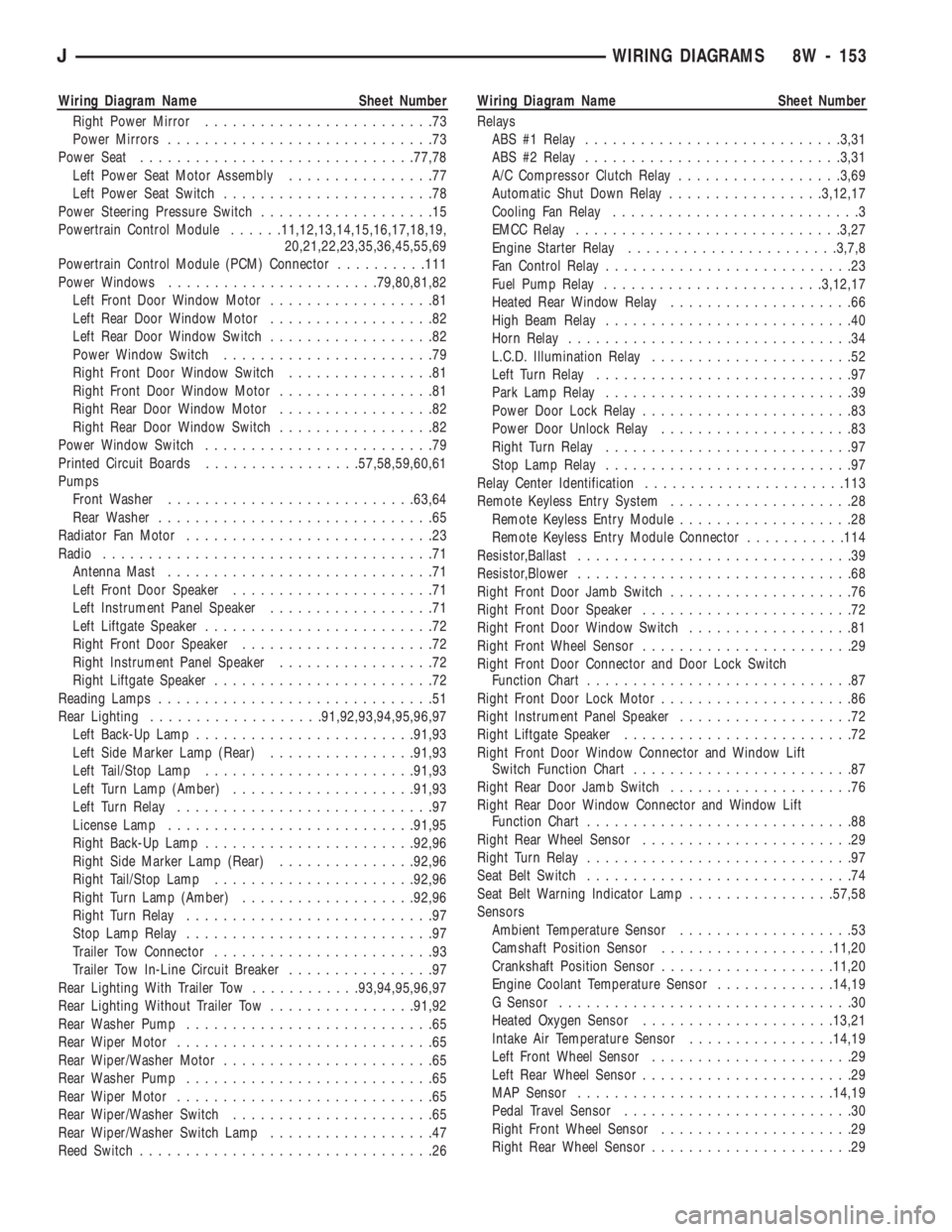
Right Power Mirror.........................73
Power Mirrors.............................73
Power Seat..............................77,78
Left Power Seat Motor Assembly................77
Left Power Seat Switch.......................78
Power Steering Pressure Switch...................15
Powertrain Control Module......11,12,13,14,15,16,17,18,19,
20,21,22,23,35,36,45,55,69
Powertrain Control Module (PCM) Connector..........111
Power Windows.......................79,80,81,82
Left Front Door Window Motor..................81
Left Rear Door Window Motor..................82
Left Rear Door Window Switch..................82
Power Window Switch.......................79
Right Front Door Window Switch................81
Right Front Door Window Motor.................81
Right Rear Door Window Motor.................82
Right Rear Door Window Switch.................82
Power Window Switch.........................79
Printed Circuit Boards.................57,58,59,60,61
Pumps
Front Washer...........................63,64
Rear Washer..............................65
Radiator Fan Motor...........................23
Radio....................................71
Antenna Mast.............................71
Left Front Door Speaker......................71
Left Instrument Panel Speaker..................71
Left Liftgate Speaker.........................72
Right Front Door Speaker.....................72
Right Instrument Panel Speaker.................72
Right Liftgate Speaker........................72
Reading Lamps..............................51
Rear Lighting...................91,92,93,94,95,96,97
Left Back-Up Lamp........................91,93
Left Side Marker Lamp (Rear)................91,93
Left Tail/Stop Lamp.......................91,93
Left Turn Lamp (Amber)....................91,93
Left Turn Relay............................97
License Lamp...........................91,95
Right Back-Up Lamp.......................92,96
Right Side Marker Lamp (Rear)...............92,96
Right Tail/Stop Lamp......................92,96
Right Turn Lamp (Amber)...................92,96
Right Turn Relay...........................97
Stop Lamp Relay...........................97
Trailer Tow Connector........................93
Trailer Tow In-Line Circuit Breaker................97
Rear Lighting With Trailer Tow............93,94,95,96,97
Rear Lighting Without Trailer Tow................91,92
Rear Washer Pump...........................65
Rear Wiper Motor............................65
Rear Wiper/Washer Motor.......................65
Rear Washer Pump...........................65
Rear Wiper Motor............................65
Rear Wiper/Washer Switch......................65
Rear Wiper/Washer Switch Lamp..................47
Reed Switch................................26Wiring Diagram Name Sheet Number
Relays
ABS #1 Relay............................3,31
ABS #2 Relay............................3,31
A/C Compressor Clutch Relay..................3,69
Automatic Shut Down Relay.................3,12,17
Cooling Fan Relay...........................3
EMCC Relay.............................3,27
Engine Starter Relay.......................3,7,8
Fan Control Relay...........................23
Fuel Pump Relay........................3,12,17
Heated Rear Window Relay....................66
High Beam Relay...........................40
Horn Relay...............................34
L.C.D. Illumination Relay......................52
Left Turn Relay............................97
Park Lamp Relay...........................39
Power Door Lock Relay.......................83
Power Door Unlock Relay.....................83
Right Turn Relay...........................97
Stop Lamp Relay...........................97
Relay Center Identification......................113
Remote Keyless Entry System....................28
Remote Keyless Entry Module...................28
Remote Keyless Entry Module Connector...........114
Resistor,Ballast..............................39
Resistor,Blower..............................68
Right Front Door Jamb Switch....................76
Right Front Door Speaker.......................72
Right Front Door Window Switch..................81
Right Front Wheel Sensor.......................29
Right Front Door Connector and Door Lock Switch
Function Chart.............................87
Right Front Door Lock Motor.....................86
Right Instrument Panel Speaker...................72
Right Liftgate Speaker.........................72
Right Front Door Window Connector and Window Lift
Switch Function Chart........................87
Right Rear Door Jamb Switch....................76
Right Rear Door Window Connector and Window Lift
Function Chart.............................88
Right Rear Wheel Sensor.......................29
Right Turn Relay.............................97
Seat Belt Switch.............................74
Seat Belt Warning Indicator Lamp................57,58
Sensors
Ambient Temperature Sensor...................53
Camshaft Position Sensor...................11,20
Crankshaft Position Sensor...................11,20
Engine Coolant Temperature Sensor.............14,19
G Sensor................................30
Heated Oxygen Sensor.....................13,21
Intake Air Temperature Sensor................14,19
Left Front Wheel Sensor......................29
Left Rear Wheel Sensor.......................29
MAP Sensor............................14,19
Pedal Travel Sensor.........................30
Right Front Wheel Sensor.....................29
Right Rear Wheel Sensor......................29
JWIRING DIAGRAMS 8W - 153
Page 765 of 1784
Wiring Diagram Name Sheet Number
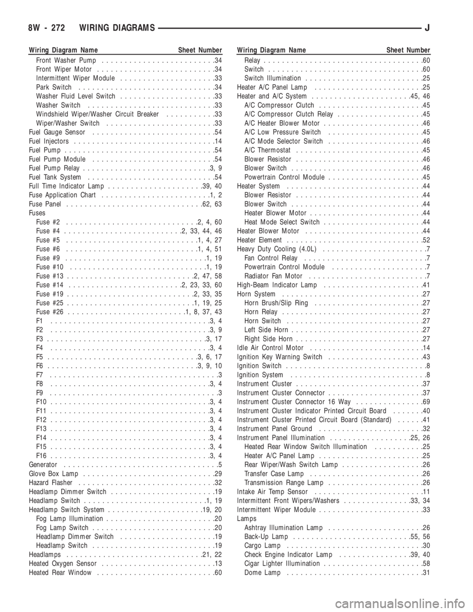
Front Washer Pump.........................34
Front Wiper Motor..........................34
Intermittent Wiper Module.....................33
Park Switch..............................34
Washer Fluid Level Switch.....................33
Washer Switch............................33
Windshield Wiper/Washer Circuit Breaker...........33
Wiper/Washer Switch........................33
Fuel Gauge Sensor...........................54
Fuel Injectors...............................14
Fuel Pump.................................54
Fuel Pump Module...........................54
Fuel Pump Relay............................3,9
Fuel Tank System............................54
Full Time Indicator Lamp.....................39, 40
Fuse Application Chart........................1,2
Fuse Panel..............................62, 63
Fuses
Fuse #2.............................2,4,60
Fuse #4..........................2,33,44,46
Fuse #5.............................1,4,27
Fuse #6.............................1,4,51
Fuse #9...............................1,19
Fuse #10..............................1,19
Fuse #13............................2,47,58
Fuse #14.........................2,23,33,60
Fuse #19............................2,33,35
Fuse #25............................1,19,25
Fuse #26..........................1,8,37,43
F1 ...................................3,4
F2 ...................................3,9
F3 ...................................3,17
F4 ...................................3,4
F5 .................................3,6,17
F6 .................................3,9,10
F7 .....................................3
F8 ...................................3,4
F9 .....................................3
F10 ...................................3,4
F11 ...................................3,4
F12 ...................................3,4
F13 ...................................3,4
F14 ...................................3,4
F15 ...................................3,4
F16 ...................................3,4
Generator..................................5
Glove Box Lamp.............................29
Hazard Flasher..............................32
Headlamp Dimmer Switch.......................19
Headlamp Switch...........................1,19
Headlamp Switch System.....................19, 20
Fog Lamp Illumination........................20
Fog Lamp Switch...........................20
Headlamp Dimmer Switch.....................19
Headlamp Switch...........................19
Headlamps..............................21, 22
Heated Oxygen Sensor.........................13
Heated Rear Window..........................60Wiring Diagram Name Sheet Number
Relay...................................60
Switch..................................60
Switch Illumination..........................25
Heater A/C Panel Lamp........................25
Heater and A/C System......................45, 46
A/C Compressor Clutch.......................45
A/C Compressor Clutch Relay...................45
A/C Heater Blower Motor......................46
A/C Low Pressure Switch.....................45
A/C Mode Selector Switch.....................46
A/C Thermostat............................45
Blower Resistor............................46
Blower Switch.............................46
Powertrain Control Module.....................45
Heater System..............................44
Blower Resistor............................44
Blower Switch.............................44
Heater Blower Motor.........................44
Heat Mode Select Switch......................44
Heater Blower Motor..........................44
Heater Element..............................52
Heavy Duty Cooling (4.0L).......................7
Fan Control Relay...........................7
Powertrain Control Module.....................7
Radiator Fan Motor..........................7
High-Beam Indicator Lamp......................41
Horn System...............................27
Horn Brush/Slip Ring........................27
Horn Relay...............................27
Horn Switch..............................27
Left Side Horn.............................27
Right Side Horn............................27
Idle Air Control Motor.........................14
Ignition Key Warning Switch.....................43
Ignition Switch...............................8
Ignition System..............................8
Instrument Cluster............................37
Instrument Cluster Connector.....................37
Instrument Cluster Connector 16 Way...............69
Instrument Cluster Indicator Printed Circuit Board.......40
Instrument Cluster Printed Circuit Board (Standard)......41
Instrument Panel Ground.......................32
Instrument Panel Illumination..................25, 26
Heated Rear Window Switch Illumination...........25
Heater A/C Panel Lamp.......................25
Rear Wiper/Wash Switch Lamp..................26
Transfer Case Lamp.........................26
Transmission Range Lamp.....................26
Intake Air Temp Sensor........................11
Intermittent Front Wipers/Washers...............33, 34
Intermittent Wiper Module.......................33
Lamps
Ashtray Illumination Lamp.....................26
Back-Up Lamp..........................55, 56
Cargo Lamp..............................30
Check Engine Indicator Lamp................39, 40
Cigar Lighter Illumination......................58
Dome Lamp..............................31
8W - 272 WIRING DIAGRAMSJ
Page 766 of 1784
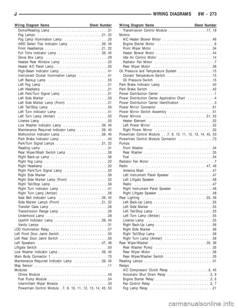
Wiring Diagram Name Sheet Number
Dome/Reading Lamp.........................31
Fog Lamps............................21, 22
Fog Lamp Illumination Lamp...................20
4WD Select Trac Indicator Lamp..............39, 40
Front Headlamps.........................21, 22
Full Time Indicator Lamp...................39, 40
Glove Box Lamp...........................29
Heated Rear Window Lamp....................25
Heater A/C Panel Lamp.......................25
High-Beam Indicator Lamp.....................41
Instrument Cluster Illumination Lamps.............41
Left Backup Lamp..........................55
Left Fog Lamp.............................21
Left Headlamp.............................21
Left Park/Turn Signal Lamp....................21
Left Side Marker...........................55
Left Side Marker Lamp (Front)..................21
Left Tail/Stop Lamp.........................55
Left Turn Indicator Lamp......................41
Left Turn Lamp (Amber)......................55
License Lamp.............................55
Low Washer Indicator Lamp.................39, 40
Maintenance Required Indicator Lamp...........39, 40
Malfunction Indicator Lamp..................39, 40
Park Brake Indicator Lamp.....................40
Park/Turn Signal Lamps....................21, 22
Reading Lamp.............................31
Rear Wiper/Wash Switch Lamp..................26
Right Back-up Lamp.........................56
Right Fog Lamp............................22
Right Headlamp............................22
Right Park/Turn Signal Lamp...................22
Right Side Marker..........................56
Right Side Marker Lamp (Front).................22
Right Tail/Stop Lamp........................56
Right Turn Indicator Lamp.....................41
Right Turn Lamp (Amber).....................56
Seat Belt Indicator Lamp...................39, 40
Side Marker Lamps (Front)..................21, 22
Transfer Case Lamp.........................26
Transmission Range Lamp.....................26
Underhood Lamp...........................28
Upshift Indicator Lamp.....................39, 40
Vanity Lamps.............................31
LCD Illumination Relay.........................57
Left Front Door Jamb Switch.....................50
Left Rear Door Jamb Switch.....................50
Left Speakers............................47, 48
Liftgate Switch..............................50
Low Washer Indicator Lamp...................39, 40
Main Body Connector 1........................70
Maintenance Required Indicator Lamp............39, 40
Map Sensor................................11
Modules
Chime Module.............................43
Fuel Pump Module..........................54
Intermittent Wiper Module.....................33
Powertrain Control Module . .7, 9, 10, 11, 12, 13, 14, 45, 53Wiring Diagram Name Sheet Number
Transmission Control Module.................17, 18
Motors
A/C Heater Blower Motor......................46
Engine Starter Motor.........................6
Front Wiper Motor..........................34
Heater Blower Motor.........................44
Idle Air Control Motor........................14
Radiator Fan Motor..........................7
Rear Wiper Motor..........................36
Oil Pressure and Temperature System...............15
Coolant Temperature Switch....................15
Oil Pressure Switch.........................15
Park Brake Indicator Lamp......................40
Park Brake Switch............................42
Power Distribution Center........................1
Power Distribution Center Application Chart............4
Power Distribution Center Identification...............3
Power Mirror Connector........................61
Power Mirror Switch Assembly...................51
Power Mirrors............................51, 52
Heater Element............................52
Left Power Mirror..........................52
Right Power Mirror.........................52
Powertrain Control Module . . .7, 9, 10, 11, 12, 13, 14, 45, 53
Powertrain Control Module Connector...............73
Pumps
Front Washer.............................34
Rear Washer..............................35
Fuel...................................54
Radiator Fan Motor............................7
Radio.................................47, 48
Antenna Mast.............................47
Left Instrument Panel Speaker..................47
Left Liftgate Speaker.........................48
Radio..................................47
Right Instrument Panel Speaker.................48
Right Liftgate Speaker........................48
Rear Lighting............................55, 56
Left Back-Up Lamp..........................55
Left Side Marker...........................55
Left Tail/Stop Lamp.........................55
Left Turn Lamp (Amber)......................55
License Lamp.............................55
Right Back-Up Lamp.........................56
Right Side Marker..........................56
Right Tail/Stop Lamp........................56
Right Turn Lamp (Amber).....................56
Rear Wiper/Washer.........................35, 36
Rear Washer Pump.........................35
Rear Wiper Motor..........................36
Rear Wiper/Washer Switch.....................35
Reading Lamps..............................31
Relays
A/C Compressor Clutch Relay.................3,45
Automatic Shut Down Relay...................3,9
Engine Starter Relay........................3,6
Fan Control Relay.........................3,7
Fog Lamp Relay...........................21
JWIRING DIAGRAMS 8W - 273
Page 1755 of 1784

GRILLE OPENING PANEL (GOP), GRILLE.....23-3
GRILLEÐXJ VEHICLES, AIR EXHAUST.....23-30
GROUND, POWER.....................14-22
GROUP INDEX; ELECTRICAL..............8A-1
GUARD, BRUSH........................23-3
GUARD/EDGE PROTECTOR STRIP, DOOR
EDGE..............................23-61
GUIDES AND CHARTS, DIAGNOSIS........21-76
HALF METAL DOOR MIRROR (EXTERNAL) . . 23-158
HALF-METAL DOOR LATCH STRIKER......23-175
HALF-METAL SOFT TOP DOOR..........23-173
HAND DRIVE, BATTERY CLASSIFICATIONS
AND RATINGSÐLEFT.................8B-10
HAND DRIVE, BATTERY CLASSIFICATIONS
AND RATINGSÐRIGHT................8B-10
HAND DRIVE, BATTERY REPLACEMENTÐ
LEFT...............................8B-1
HAND DRIVE, BATTERY REPLACEMENTÐ
RIGHT..............................8B-2
HAND DRIVE, BELT SERVICEÐEXCEPT
RIGHT..............................7-34
HAND DRIVE, BELT SERVICEÐWITH
RIGHT..............................7-35
HAND DRIVE, DRIVERS DOOR POWER
LOCK SWITCHÐ2-DOOR LEFT...........8P-2
HAND DRIVE, DRIVERS DOOR POWER
LOCK SWITCHÐ2-DOOR RIGHT..........8P-3
HAND DRIVE, DRIVERS DOOR POWER
WINDOW SWITCHÐ2-DOOR LEFT........8S-6
HAND DRIVE, DRIVERS DOOR POWER
WINDOW SWITCHÐ2-DOOR RIGHT......8S-7
HAND DRIVE, GENERATOR
REPLACEMENTÐLEFT.................8B-7
HAND DRIVE, GENERATOR
REPLACEMENTÐRIGHT................8B-9
HAND DRIVE (RHD), BELT TENSIONÐ
EXCEPT RIGHT.......................7-33
HAND DRIVE (RHD), BELT TENSIONÐ
RIGHT..............................7-34
HAND DRIVE VEHICLES, RIGHT............23-1
HAND DRIVE, WASHER PUMP
REPLACEMENTÐLEFT.................8K-2
HAND DRIVE, WASHER PUMP
REPLACEMENTÐRIGHT................8K-3
HANDLE, DOOR EXTERNAL..............23-55
HANDLE, FULL-METAL DOOR ASSIST.....23-175
HANDLE, FULL-METAL DOOR LATCH
EXTERNAL RELEASE.................23-178
HANDLE, FULL-METAL DOOR LATCH
INSIDE RELEASE AND LOCK...........23-175
HANDLE, FULL-METAL DOOR WINDOW
GLASS REGULATOR.................23-175
HANDLE, TAILGATE LATCH AND
RELEASE..........................23-160
HANDLEÐXJ VEHICLES, ASSIST.........23-118
HANGER BRACKET, MUFFLER/TAILPIPE.....13-16
HARD TOP DOME/CARGO LAMP BULB
REPLACEMENTÐYJ VEHICLES..........8L-20
HARD TOP LIFTGATE GLASS............23-162
HARD TOP QUARTER WINDOW GLASS....23-188
HARD TOP REPAIR....................23-165
HARD TOP ROOF VENT................23-165
HARD TOP SERVICE...................23-164
HARD TOP SERVICE INFORMATION.......23-164
HAZARD LAMPSÐXJ....................8J-1
HAZARD LAMPSÐYJ....................8J-2
HCU DIAGNOSIS........................5-4
HCU INSTALLATIONÐXJ.................5-54
HCU INSTALLATIONÐYJ.................5-54
HCU PUMP AND PEDAL TRAVEL
SENSOR OPERATION...................5-44
HCU REMOVALÐXJ.....................5-53
HCU REMOVALÐYJ.....................5-54
HCU SOLENOID VALVE OPERATION.........5-43
HEAD COVER, ENGINE CYLINDER......9-18,9-59
HEAD, ENGINE CYLINDER............9-19,9-60
HEAD GASKET FAILURE DIAGNOSIS,
ENGINE CYLINDER.....................9-5
HEADLAMP BEAM ADJUSTMENT...........8L-3
HEADLAMP BULB REPLACEMENT
..........8L-3
HEADLAMP DELAY FUNCTION TROUBLE
DIAGNOSISÐXJ VEHICLES
.............8L-16
HEADLAMP DELAY MODULE
REPLACEMENTÐXJ VEHICLES
..........8L-16
HEADLAMP DELAY MODULEÐXJ
VEHICLES, SENTINEL
.................8L-15HEADLAMP DIMMER SWITCH
REPLACEMENT.......................8L-6
HEADLAMP SWITCH REPLACEMENT........8L-4
HEADLAMP SWITCH/ILLUMINATION
RHEOSTAT..........................8E-21
HEADLAMP TROUBLE DIAGNOSISÐ
XJ VEHICLES.........................8L-1
HEADLAMP TROUBLE DIAGNOSISÐYJ
VEHICLES...........................8L-2
HEADLAMPS...........................0-35
HEADLINER.........................23-121
HEAT SHIELDS........................14-12
HEAT SHIELDS, EXHAUST................11-1
HEAT SHIELDS, MUFFLER AND TAILPIPE . . . 13-17
HEATER AND A/C CONTROL PANEL
REPLACEMENT......................24-26
HEATER CONTROL CABLE REPLACEMENT . . . 24-30
HEATER CONTROL PANEL REPLACEMENT . . . 24-39
HEATER CORE........................24-28
HEATER CORE AND HOUSING............24-40
HEATER CORE HOUSING REPLACEMENT . . . 24-29
HEATER, ENGINE BLOCK.................7-37
HEATER/DEFROSTER OPERATION.........24-37
HEATER/DEFROSTER/INSTRUMENT
PANEL OUTLET DOOR VACUUM MOTOR
REPLACEMENT......................24-30
HEATING ELEMENT TEST, OXYGEN
SENSOR (O2S)......................14-45
HEATING SCHEMATIC...................24-24
HEATING SYSTEM DIAGNOSIS............24-11
HEATING SYSTEMÐYJ VEHICLES.........24-14
HIGH LINE CLUSTER...................8E-12
HIGH MOUNTED STOP LAMP (CHMSL)Ð
XJ, CENTER.........................8L-10
HIGH MOUNTED STOP LAMP (CHMSL)Ð
YJ, CENTER.........................8L-11
HINGE, LIFTGATE......................23-67
HINGE REPLACEMENT, HOOD.............23-9
HINGE, TAILGATE.....................23-159
HINGE/HINGE PIN REPLACEMENT, DOOR . . . 23-58
HINGES, FULL-METAL DOOR............23-179
HITCHES, TRAILER.....................23-88
HOISTING AND TOWING, JUMP
STARTING,............................0-7
HOLDDOWN AND FLOOR BRACKETSÐ
XJ VEHICLES, SPARE TIRE/WHEEL......23-128
HONING CYLINDER BORES................9-2
HOOD..........................23-6,23-137
HOOD ADJUSTMENT....................23-9
HOOD ALIGNMENT....................23-138
HOOD HINGE REPLACEMENT..............23-9
HOOD INSULATOR PANEL..............23-138
HOOD LATCH REPLACEMENT............23-10
HOOD LATCH STRIKER REPLACEMENT.....23-10
HOOD SAFETY LATCH.................23-139
HOOKÐXJ VEHICLES, REAR TOW.........23-87
HOOKS, FRONT TOW....................13-5
HOOKS, TOW.........................13-14
HORN PAD REPLACEMENT, HORN SWITCH . . . 8G-3
HORN SWITCH (HORN PAD)
REPLACEMENT.......................8G-3
HOSE REPLACEMENT, PRESSURE AND
RETURN............................19-9
HOSE ROUTING SCHEMATICS,
VACUUM............................25-1
HOSE SPLASH SHIELDÐXJ VEHICLES,
FUEL FILLER........................23-86
HOSES, BRAKE BLEEDINGÐBRAKE FLUID
AND LEVELÐBRAKELINES..............5-13
HOSES, BRAKELINES....................5-15
HOSES, COOLING SYSTEM...............7-26
HOSES/TUBING, RUBBER AND PLASTIC.....0-28
HOUSING, AIR CLEANER; EMISSION
CONTROL SYSTEMS...................25-8
HOUSING, AIR CLEANER; FUEL SYSTEM....14-54
HOUSING AND PARK LOCK COMPONENT
OVERHAUL, ADAPTER................21-120
HOUSING END PLUG...................19-26
HOUSING, EVAPORATOR................24-42
HOUSING, EVAPORATOR/BLOWER.........24-33
HOUSING, HEATER CORE................24-40
HOUSING LEAK DIAGNOSIS, CONVERTER
. . . 21-73
HOUSING, LIFTGATE LICENSE PLATE
LAMP
..............................23-72
HOUSING REPLACEMENT, CLUTCH
.........6-11
HOUSING REPLACEMENT, HEATER CORE
. . . 24-29HOUSING SEAL REPLACEMENT,
ADAPTER..........................21-182
HOUSINGS, INSTRUMENT CLUSTER
AND GAUGE........................23-190
HUB BEARING AND AXLE SHAFT...........2-24
HYDRAULIC CLUTCH....................0-22
HYDRAULIC COMPONENTS................5-1
HYDRAULIC CONTROL UNIT (HCU).........5-39
HYDRAULIC FLOW DURING FULL
THROTTLE 3-2 DOWNSHIFT............21-92
HYDRAULIC FLOW DURING PART
THROTTLE 3-2 DOWNSHIFT............21-91
HYDRAULIC FLOW IN D RANGE FIRST
GEAR..............................21-87
HYDRAULIC FLOW IN D RANGE SECOND
GEAR..............................21-88
HYDRAULIC FLOW IN D RANGE THIRD
GEAR..............................21-89
HYDRAULIC FLOW IN MANUAL FIRST
GEAR (1) POSITION..................21-94
HYDRAULIC FLOW IN MANUAL SECOND
(2) RANGE..........................21-93
HYDRAULIC FLOW IN PARK AND NEUTRAL . . . 21-86
HYDRAULIC FLOW IN REVERSE..........21-95
HYDRAULIC FLOW IN THIRD GEAR
(CONVERTER CLUTCH ENGAGED)........21-90
HYDRAULIC LINKAGE INSTALLATION,
CLUTCH.............................6-12
HYDRAULIC LINKAGE REMOVAL,
CLUTCH.............................6-11
HYDRAULIC PRESSURE TEST......21-71,21-168
HYDRAULIC SYSTEM..................21-160
HYDRAULIC TAPPETS...............9-24,9-65
HYDROMETER TEST....................8A-3
IDENTIFICATION, AW-4 VALVE AND
SPRING...........................21-330
IDENTIFICATION, CIRCUIT................8W-2
IDENTIFICATION, COMPONENT............8W-2
IDENTIFICATION, ENGINE AND
TRANSMISSION/TRANSFER CASE.....INTRO.-3
IDENTIFICATION, MAJOR COMPONENT . . INTRO.-3
IDENTIFICATION NUMBER (VIN)
DECODING, VEHICLE...............INTRO.-2
IDENTIFICATION NUMBER (VIN) PLATE,
VEHICLE.........................INTRO.-1
IDENTIFICATION, TRANSFER CASE
. 21-273,21-293
IDENTIFICATION, TRANSMISSION
.....21-1,21-32,
21-66,21-157
IDENTIFICATION, WIRE CODE
.............8W-2
IDENTIFICATION, WIRING AND
COMPONENT
.......................8W-13
IDLE AIR CONTROL (IAC) MOTOR
.........14-56
IDLE AIR CONTROL (IAC) MOTORÐPCM
OUTPUT
............................14-25
IDLE AIR CONTROL MOTOR TEST
.........14-46
IDLE SWITCHÐPCM INPUT, EXTENDED
....14-21
IDLE SWITCH TEST, EXTENDED
...........14-45
IGNITION CABLES, DISTRIBUTOR CAP
AND ROTOR
.........................0-18
IGNITION CIRCUIT SENSEÐPCM INPUT
....14-21
IGNITION COIL; FUEL SYSTEM
...........14-57
IGNITION COIL; IGNITION SYSTEMS
. . 8D-4,8D-11,
8D-26
IGNITION COILÐPCM OUTPUT
...........14-26
IGNITION COIL RESISTANCE
.............8D-11
IGNITION KEY WARNING SWITCH
REPLACEMENT
.......................8U-4
IGNITION OFF DRAW (IOD) DIAGNOSIS
.....8A-8
IGNITION SECONDARY CIRCUIT
DIAGNOSIS
.........................8D-12
IGNITION SWITCH; BRAKES
...............5-42
IGNITION SWITCH CONTINUITY TESTS
.....8D-31
IGNITION SWITCH; IGNITION SYSTEMS
....8D-30
IGNITION SWITCH INSTALLATION/
ADJUSTMENT
.......................8D-31
IGNITION SWITCH REMOVAL
............8D-30
IGNITION SWITCH TESTING
.............8D-30
IGNITION TIMING
......................8D-14
IGNITION WIRING, SECONDARY
...........8W-1
ILLUMINATED ENTRY SYSTEM SERVICE
INFORMATION
.......................8L-20
ILLUMINATED ENTRY SYSTEM TROUBLE
DIAGNOSIS
....................8L-21,8L-22
JINDEX11
Description Group-Page Description Group-Page Description Group-Page