airbag JEEP CHEROKEE 1995 Service User Guide
[x] Cancel search | Manufacturer: JEEP, Model Year: 1995, Model line: CHEROKEE, Model: JEEP CHEROKEE 1995Pages: 2198, PDF Size: 82.83 MB
Page 465 of 2198
BULB APPLICATIONÐXJ VEHICLES
GENERAL INFORMATION
The following Bulb Application Table lists the lamp
title on the left side of the column and trade number
or part number on the right.
CAUTION: Do not use bulbs that have a higher can-
dle power than the bulb listed in the Bulb Applica-
tion Table. Damage to lamp can result.
Do not touch halogen bulbs with fingers or other
oily surfaces. Bulb life will be reduced.
EXTERIOR LAMPSÐXJ
Back-up .................................................................1156
Center High Mounted Stoplamp ..........................922
Fog ............................................................................H3
Front Side Marker .................................................194
Headlamp/Sealed Beam....................................H6054
License Plate ..........................................................168
License Plate W/Outside Spare ..............................67
Park/Turn Signal ............................................2057NA
Tail/Stop ................................................................2057
Turn Signal ...........................................................1156
INTERIOR LAMPSÐXJ
Service procedures for most of the lamps in the in-
strument panel, Instrument cluster and switches are
located in Group 8E, Instrument Panel and Gauges.
Some components have lamps that can only be ser-
viced by an Authorized Service Center (ASC) after
the component is removed from the vehicle. Contact
local dealer for location of nearest ASC.
Cargo .......................................................................561
Dome .......................................................................561
Dome/Reading.........................................................906Glove Compartment ...............................................194
Overhead Console ..................................................912
Under Hood ............................................................105
Vanity Mirror ...........................................................74
Underpanel Courtesy.............................................168
INDICATOR LAMPS
Service procedures for most of the lamps in the in-
strument panel, instrument cluster and switches are
located in Group 8E, Instrument Panel and Gauges.
A/C Control ...............................................................74
Airbag ........................................................................74
Anti-lock Brake ........................................................74
Ash Receiver .........................................................1891
Brake Warning .........................................................74
Check Engine ...........................................................74
Cigar Lighter ............................................................53
Diesel Wait ...............................................................74
Fasten Seat Belts ....................................................74
Four Wheel Drive ....................................................74
Generator ................................................................194
Generator/Diesel.......................................................74
Heater Control .........................................................74
High Beam..............................................................194
Illumination ............................................................194
Low Fuel .................................................................194
Low Washer Fluid....................................................74
Radio ......................................................................ASC
Rocker Switch...........................................................37
Seat Belt ...................................................................74
Transfer Case .........................................................658
Transmission Floor Shift.......................................658
Turn Signal.............................................................194
Shift ...........................................................................74
Water In Fuel ...........................................................74
8L - 18 LAMPSÐXJ VEHICLESJ
Page 480 of 2198
RESTRAINT SYSTEMS
CONTENTS
page page
AIRBAG SYSTEM......................... 1
DIAGNOSIS............................. 2GENERAL INFORMATION.................. 1
SERVICE PROCEDURES................... 2
AIRBAG SYSTEM
WARNING: THIS AIRBAG SYSTEM IS A SENSITIVE,
COMPLEX MECHANICAL UNIT. BEFORE ATTEMPT-
ING TO REMOVE OR INSTALL THE AIRBAG SYS-
TEM OR RELATED STEERING WHEEL AND
STEERING COLUMN COMPONENTS YOU MUST
FIRST DISARM THE AIRBAG FIRING MECHANISM.
FAILURE TO DO SO COULD RESULT IN ACCIDEN-
TAL DEPLOYMENT AND POSSIBLE PERSONAL IN-
JURY.
WARNING: THE AIRBAG MODULE INFLATOR/SEN-
SOR ASSEMBLY CONTAINS SODIUM AZIDE AND
POTASSIUM NITRATE. THESE MATERIALS ARE
POISONOUS AND EXTREMELY FLAMMABLE. CON-
TACT WITH ACID, WATER OR HEAVY METALS MAY
PRODUCE HARMFUL AND IRRITATING GASES (SO-
DIUM HYDROXIDE IS FORMED IN THE PRESENCE
OF MOISTURE) OR COMBUSTIBLE COMPOUNDS.
DO NOT ATTEMPT TO DISMANTLE THE MODULE
OR TAMPER WITH ITS ARMING LEVER. DO NOT
PUNCTURE, INCINERATE, OR BRING INTO CON-
TACT WITH ELECTRICITY. DO NOT STORE AT TEM-
PERATURES EXCEEDING 200ÉF.WARNING: REPLACE AIRBAG SYSTEM COMPO-
NENTS WITH PARTS SPECIFIED IN THE CHRYSLER
MOPAR PARTS CATALOG ONLY. IT IS OF PARTICU-
LAR IMPORTANCE THAT ANY COMPONENTS USED
IN THIS MECHANICALLY-FIRED AIRBAG SYSTEM
NOT BE MIXED WITH COMPONENTS FROM AN
ELECTRICALLY-FIRED AIRBAG SYSTEM. SUBSTI-
TUTE PARTS MAY APPEAR THE SAME, BUT INTER-
NAL DIFFERENCES MAY RESULT IN INFERIOR
OCCUPANT PROTECTION.
WARNING: THE FASTENERS, SCREWS, AND
BOLTS, ORIGINALLY USED FOR THE AIRBAG COM-
PONENTS, HAVE SPECIAL COATINGS AND ARE
SPECIFICALLY DESIGNED FOR THE AIRBAG SYS-
TEM. THEY MUST NEVER BE REPLACED WITH ANY
SUBSTITUTES. ANYTIME A NEW FASTENER IS
NEEDED, REPLACE WITH THE CORRECT FASTEN-
ERS PROVIDED IN THE SERVICE PACKAGE OR
SPECIFIED IN THE CHRYSLER MOPAR PARTS CAT-
ALOG.
GENERAL INFORMATION
The airbag system is a standard equipment safety
device on XJ (Cherokee) models. It is designed to pro-
tect the driver from serious injury, caused by a fron-
tal impact of the vehicle. If the airbag module
assembly is defective and non-deployed, refer to
Chrysler Corporation current return list for proper
handling procedures.
Following are general descriptions of the major
components in the airbag system.AIRBAG MODULE
The airbag module protective cover is the only vis-
ible part of the system. The module is mounted di-
rectly to the steering wheel. Under the airbag
module cover, the airbag cushion and its supporting
components are contained. The airbag module con-
tains a housing to which the cushion and impact sen-
sor/inflator assembly are attached and sealed. The
airbag module is non-serviceable, and must be re-
placed if deployed or damaged in any way.
The impact sensor/inflator assembly is mounted to
the back of the module. The inflator seals the hole in
JRESTRAINT SYSTEMS 8M - 1
Page 481 of 2198
the airbag cushion so it can discharge the gas it pro-
duces directly into the cushion. The protective cover
is fitted to the front of the airbag module and forms
a decorative cover in the center of the steering wheel.
Upon airbag deployment, this cover will split hori-
zontally.
STORAGE
The airbag module must be stored in its original,
special container until used for service. Also, it must
be stored in a clean, dry environment; away from
sources of extreme heat, sparks, and high electrical
energy. Always place or store the module on a surface
with the trim cover facing up to minimize movement
in case of accidental deployment.
IMPACT SENSOR/INFLATOR ASSEMBLY
The impact sensor/inflator assembly is mounted to
the back of the airbag module. It seals the hole in
the steering wheel side of the airbag cushion so that
gas produced in the inflator can be discharged di-
rectly into the cushion.
The impact sensor provides verification of the di-
rection and severity of the impact. A spherical sens-
ing mass housed in a cylinder will move forward and
rotate a D-shaft when the vehicle is subjected to a
frontal impact of sufficient severity. Airbag inflation
is designed to occur at a precisely calibrated vehicle
deceleration force, and is not linked to vehicle road
speed.The D-shaft retains two spring-loaded firing pins.
When a firing pin is released by the D-shaft, it
strikes and ignites a primer. The primer then reacts
with the pelletized, solid generant contained in the
inflator to produce the nitrogen gas that inflates the
airbag cushion.
ARMING/DISARMING MECHANISM
The steering wheel hub incorporates an airbag
arming/disarming mechanism and a specially de-
signed nut-blocker. The nut-blocker serves as a safety
to prevent removal of the airbag module until the
unit has been disarmed. A removable plastic cover
plug on the top, outer hub of the steering wheel al-
lows access to the arming screw.
When the airbag module is disarmed, the arming
screw extends upward from the steering wheel hub.
This will prevent installation of the plastic cover
plug. Also, the nut-blocker is retracted to allow ac-
cess to the two upper airbag module mounting nuts.
When the airbag module is armed, the plastic cover
plug will install flush with the outer surface of the
steering wheel hub. In addition, the nut-blocker will
prevent access to the two upper airbag module
mounting nuts.
DIAGNOSIS
This mechanical airbag system can not be diag-
nosed or repaired. The only serviced component is
the airbag module assembly. If the airbag module isdamaged in any way or deployed, it must be re-
placed.
SERVICE PROCEDURES
AIRBAG SYSTEM SERVICE (DEPLOYED)
Any vehicle which is to be returned to use after an
airbag deployment, must have the airbag module re-
placed. This is a one-time component and cannot be
reused.
AIRBAG MODULE HANDLING
UNDEPLOYED
At no time should any source of electricity be per-
mitted near the inflator on the back of the module.
When carrying an undeployed module, the trim cover
should be pointed away from the body to minimizeinjury in the event of accidental deployment. If the
module is placed on a bench or other surface, the
plastic trim cover should be face up to minimize
movement in case of accidental deployment.
In addition, the airbag module should be disarmed
whenever the steering wheel or steering column re-
quires service or removal. Failure to observe this
warning could result in accidental airbag deployment
and possible personal injury. Refer to Group 19 -
Steering for more service procedures on steering
wheel and steering column.
8M - 2 RESTRAINT SYSTEMSJ
Page 482 of 2198
DEPLOYED
Following an airbag deployment, the vehicle inte-
rior will contain a powdery residue. This residue is
primarily sodium bicarbonate (baking soda), used as
an airbag cushion lubricant. However, there will also
be traces of sodium hydroxide powder, a chemical
byproduct of the generant used for airbag deploy-
ment. Since this powder can irritate the skin, eyes,
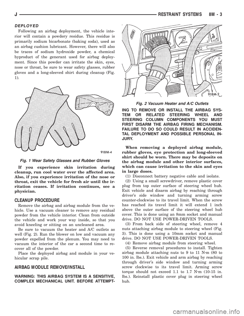
nose or throat, be sure to wear safety glasses, rubber
gloves and a long-sleeved shirt during cleanup (Fig.
1).
If you experience skin irritation during
cleanup, run cool water over the affected area.
Also, if you experience irritation of the nose or
throat, exit the vehicle for fresh air until the ir-
ritation ceases. If irritation continues, see a
physician.
CLEANUP PROCEDURE
Remove the airbag and airbag module from the ve-
hicle. Use a vacuum cleaner to remove any residual
powder from the vehicle interior. Clean from outside
the vehicle and work your way inside, so that you
avoid kneeling or sitting on an uncleaned area.
Be sure to vacuum the heater and A/C outlets as
well (Fig. 2). Run the blower on low and vacuum any
powder expelled from the plenum. You may need to
vacuum the interior of the car a second time to re-
cover all of the powder.
Place the deployed airbag and module in your ve-
hicular scrap pile.
AIRBAG MODULE REMOVE/INSTALL
WARNING: THIS AIRBAG SYSTEM IS A SENSITIVE,
COMPLEX MECHANICAL UNIT. BEFORE ATTEMPT-ING TO REMOVE OR INSTALL THE AIRBAG SYS-
TEM OR RELATED STEERING WHEEL AND
STEERING COLUMN COMPONENTS YOU MUST
FIRST DISARM THE AIRBAG FIRING MECHANISM.
FAILURE TO DO SO COULD RESULT IN ACCIDEN-
TAL DEPLOYMENT AND POSSIBLE PERSONAL IN-
JURY.
When removing a deployed airbag module,
rubber gloves, eye protection and long-sleeved
shirt should be worn. There may be deposits on
the airbag module and other interior surfaces,
which can cause irritation to the skin and eyes
in large doses.
(1) Disconnect battery negative cable and isolate.
(2) Using a small screwdriver, remove plastic cover
plug from top outer surface of steering wheel hub.
Exit vehicle and disarm airbag by reaching through
driver's side window and turning arming screw
counter-clockwise to its travel limit. When the screw
has reached its travel limit it will extend 1 inch
above the outer surface of the steering wheel hub
cover. This is done using an 8mm socket and manual
drive. DO NOT USE POWER-DRIVEN TOOLS.
(3) From back side of steering wheel, remove 4
nuts attaching airbag module to steering wheel (Fig.
3). This is done using a 10mm socket and manual
drive. DO NOT USE POWER-DRIVEN TOOLS.
(4) Remove airbag module from steering wheel.
(5) Reverse removal procedures to install. Tighten
airbag module attaching nuts to 9 to 11 Nzm (80 to
100 in. lbs.). Exit vehicle and arm airbag by reaching
through driver's side window and turning arming
screw clockwise to its travel limit. Arming screw
torque should not exceed 1.1 to 1.7 Nzm (10-15 in.
lbs.). Reinstall plastic cover plug in steering wheel
hub.
Fig. 1 Wear Safety Glasses and Rubber Gloves
Fig. 2 Vacuum Heater and A/C Outlets
JRESTRAINT SYSTEMS 8M - 3
Page 483 of 2198
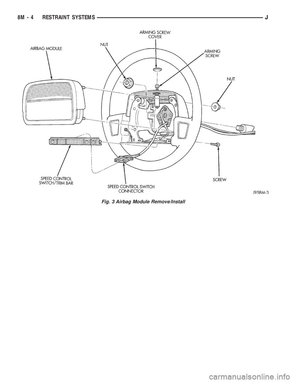
Fig. 3 Airbag Module Remove/Install
8M - 4 RESTRAINT SYSTEMSJ
Page 1346 of 2198
STEERING COLUMN GENERAL SERVICEÐXJ
INDEX
page
Airbag System........................... 47
AIRBAG SYSTEM
WARNING: THE MECHANICAL AIRBAG SYSTEM IS
A SENSITIVE, COMPLEX MECHANICAL UNIT. BE-
FORE ATTEMPTING TO REMOVE OR INSTALL THE
AIRBAG SYSTEM OR RELATED STEERING WHEEL
AND STEERING COLUMN COMPONENTS YOU
MUST FIRST DISARM THE AIRBAG FIRING MECHA-
NISM. FAILURE TO DO SO COULD RESULT IN AC-
CIDENTAL DEPLOYMENT AND POSSIBLE INJURY.
WARNING: THE AIRBAG MODULE INFLATOR/SEN-
SOR ASSEMBLY CONTAINS SODIUM AZIDE AND
POTASSIUM NITRATE. THESE MATERIALS ARE
POISONOUS AND EXTREMELY FLAMMABLE. CON-
TACT WITH ACID, WATER OR HEAVY METALS MAY
PRODUCE HARMFUL AND IRRITATING GASES (SO-
DIUM HYDROXIDE IS FORMED IN THE PRESENCE
OF MOISTURE) OR COMBUSTIBLE COMPOUNDS.
DO NOT ATTEMPT TO DISMANTLE THE MODULE
OR TAMPER WITH ITS ARMING LEVER. DO NOT
PUNCTURE, INCINERATE, OR BRING INTO CON-
TACT WITH ELECTRICITY. DO NOT STORE AT TEM-
PERATURES EXCEEDING 200ÉF.WARNING: REPLACE AIRBAG SYSTEM COMPO-
NENTS WITH PARTS SPECIFIED IN THE CHRYSLER
MOPAR PARTS CATALOG ONLY. IT IS OF PARTICU-
LAR IMPORTANCE THAT ANY COMPONENTS USED
IN THIS MECHANICALLY-FIRED AIRBAG SYSTEM
NOT BE MIXED WITH COMPONENTS FROM AN
ELECTRICALLY-FIRED AIRBAG SYSTEM. SUBSTI-
TUTE PARTS MAY APPEAR THE SAME, BUT INTER-
NAL DIFFERENCES MAY RESULT IN INFERIOR
OCCUPANT PROTECTION.
WARNING: THE FASTENERS, SCREWS, AND
BOLTS, ORIGINALLY USED FOR THE AIRBAG COM-
PONENTS, HAVE SPECIAL COATINGS AND ARE
SPECIFICALLY DESIGNED FOR THE AIRBAG SYS-
TEM. THEY MUST NEVER BE REPLACED WITH ANY
SUBSTITUTES. ANYTIME A NEW FASTENER IS
NEEDED, REPLACE WITH THE CORRECT FASTEN-
ERS PROVIDED IN THE SERVICE PACKAGE OR
SPECIFIED IN THE CHRYSLER MOPAR PARTS CAT-
ALOG.
JSTEERING 19 - 47
Page 1347 of 2198
GENERAL INFORMATION
The airbag system is a standard equipment safety
device on XJ (Cherokee) models. It is designed to pro-
tect the driver from serious injury, caused by a fron-
tal impact of the vehicle. If the airbag module
assembly is defective and non-deployed, refer to
Chrysler Corporation current return list for proper
handling procedures.
ARMING/DISARMING MECHANISM
BEFORE SERVICING A COLUMN EQUIPPED
WITH AIR BAG, REFER TO GROUP 8M, ELEC-
TRICAL FOR PROPER AND SAFE PROCE-
DURES.
The steering wheel hub incorporates an airbag
Arming/Disarming mechanism and a specially de-
signed nut-blocker. The nut-blocker serves as a safety
to prevent removal of the airbag module until the
unit has been disarmed. A removable plastic cover
plug on the top, outer hub of the steering wheel al-
lows access to the arming screw.
When the airbag module is disarmed, the arming
screw extends upward from the steering wheel hub.
This will prevent installation of the plastic cover
plug. Also, the nut-blocker is retracted to allow ac-
cess to the two upper airbag module mounting nuts.
When the airbag module is armed, the plastic cover
plug will install flush with the outer surface of the
steering wheel hub. In addition, the nut-blocker will
prevent access to the two upper airbag module
mounting nuts.THE FASTENERS, SCREWS, AND BOLTS, ORIG-
INALLY USED FOR THE AIR BAG COMPONENTS,
HAVE SPECIAL COATINGS. THIS HARDWARE IS
SPECIFICALLY DESIGNED FOR THE AIR BAG
SYSTEM. THEY MUST NEVER BE REPLACED
WITH ANY SUBSTITUTES. REPLACE WITH THE
CORRECT FASTENERS PROVIDED IN THE SER-
VICE PACKAGE OR FASTENERS IN THE PARTS
BOOK.
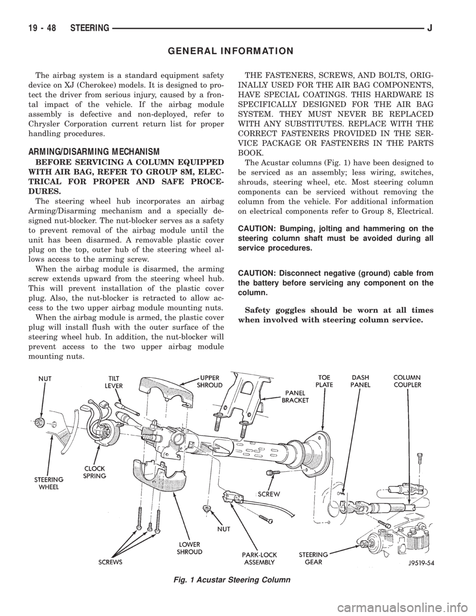
The Acustar columns (Fig. 1) have been designed to
be serviced as an assembly; less wiring, switches,
shrouds, steering wheel, etc. Most steering column
components can be serviced without removing the
column from the vehicle. For additional information
on electrical components refer to Group 8, Electrical.
CAUTION: Bumping, jolting and hammering on the
steering column shaft must be avoided during all
service procedures.
CAUTION: Disconnect negative (ground) cable from
the battery before servicing any component on the
column.
Safety goggles should be worn at all times
when involved with steering column service.
Fig. 1 Acustar Steering Column
19 - 48 STEERINGJ
Page 1348 of 2198
AIRBAG MODULE REMOVEÐINSTALL
WARNING: THIS AIRBAG SYSTEM IS A SENSITIVE,
COMPLEX MECHANICAL UNIT. BEFORE ATTEMPT-
ING TO REMOVE OR INSTALL THE AIRBAG SYS-
TEM OR RELATED STEERING WHEEL AND
STEERING COLUMN COMPONENTS YOU MUST
FIRST DISARM THE AIRBAG FIRING MECHANISM.
FAILURE TO DO SO COULD RESULT IN ACCIDEN-
TAL DEPLOYMENT AND POSSIBLE PERSONAL IN-
JURY.
When removing a deployed airbag module,
rubber gloves, eye protection and long-sleeved
shirt should be worn. There may be deposits on
the airbag module and other interior surfaces,
which can cause irritation to the skin and eyes
in large doses.
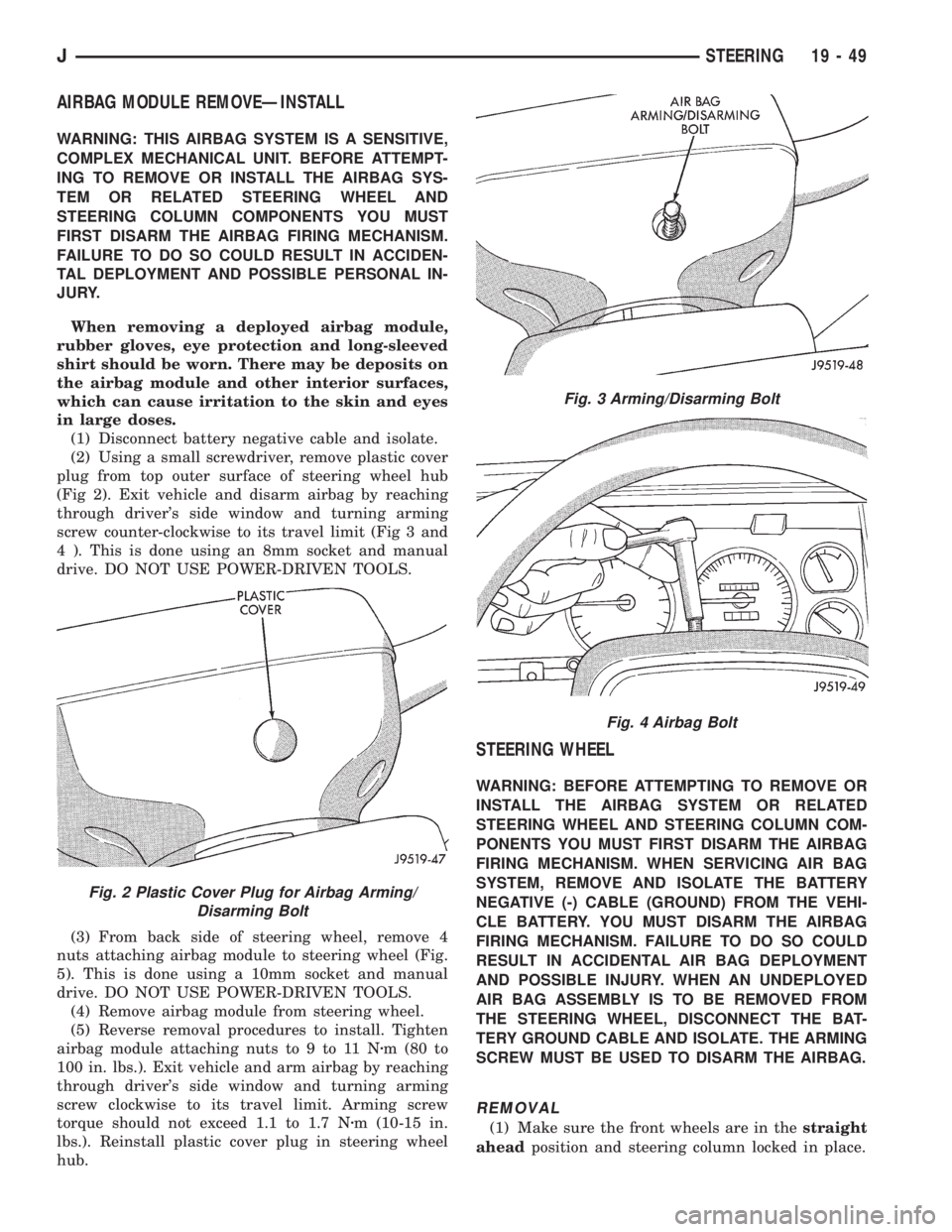
(1) Disconnect battery negative cable and isolate.
(2) Using a small screwdriver, remove plastic cover
plug from top outer surface of steering wheel hub
(Fig 2). Exit vehicle and disarm airbag by reaching
through driver's side window and turning arming
screw counter-clockwise to its travel limit (Fig 3 and
4 ). This is done using an 8mm socket and manual
drive. DO NOT USE POWER-DRIVEN TOOLS.
(3) From back side of steering wheel, remove 4
nuts attaching airbag module to steering wheel (Fig.
5). This is done using a 10mm socket and manual
drive. DO NOT USE POWER-DRIVEN TOOLS.
(4) Remove airbag module from steering wheel.
(5) Reverse removal procedures to install. Tighten
airbag module attaching nuts to 9 to 11 Nzm (80 to
100 in. lbs.). Exit vehicle and arm airbag by reaching
through driver's side window and turning arming
screw clockwise to its travel limit. Arming screw
torque should not exceed 1.1 to 1.7 Nzm (10-15 in.
lbs.). Reinstall plastic cover plug in steering wheel
hub.
STEERING WHEEL
WARNING: BEFORE ATTEMPTING TO REMOVE OR
INSTALL THE AIRBAG SYSTEM OR RELATED
STEERING WHEEL AND STEERING COLUMN COM-
PONENTS YOU MUST FIRST DISARM THE AIRBAG
FIRING MECHANISM. WHEN SERVICING AIR BAG
SYSTEM, REMOVE AND ISOLATE THE BATTERY
NEGATIVE (-) CABLE (GROUND) FROM THE VEHI-
CLE BATTERY. YOU MUST DISARM THE AIRBAG
FIRING MECHANISM. FAILURE TO DO SO COULD
RESULT IN ACCIDENTAL AIR BAG DEPLOYMENT
AND POSSIBLE INJURY. WHEN AN UNDEPLOYED
AIR BAG ASSEMBLY IS TO BE REMOVED FROM
THE STEERING WHEEL, DISCONNECT THE BAT-
TERY GROUND CABLE AND ISOLATE. THE ARMING
SCREW MUST BE USED TO DISARM THE AIRBAG.
REMOVAL
(1) Make sure the front wheels are in thestraight
aheadposition and steering column locked in place.
Fig. 2 Plastic Cover Plug for Airbag Arming/
Disarming Bolt
Fig. 3 Arming/Disarming Bolt
Fig. 4 Airbag Bolt
JSTEERING 19 - 49
Page 1349 of 2198
(2) Disconnect the battery negative (ground) cable
and isolate.
(3) Disarm the airbag (refer to group 8M, Electri-
cal for proper and safe procedures).
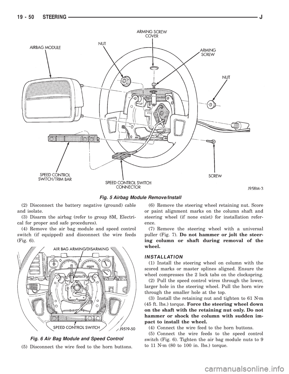
(4) Remove the air bag module and speed control
switch (if equipped) and disconnect the wire feeds
(Fig. 6).
(5) Disconnect the wire feed to the horn buttons.(6) Remove the steering wheel retaining nut. Score
or paint alignment marks on the column shaft and
steering wheel (if none exist) for installation refer-
ence.
(7) Remove the steering wheel with a universal
puller (Fig. 7).Do not hammer or jolt the steer-
ing column or shaft during removal of the
wheel.
INSTALLATION
(1) Install the steering wheel on column with the
scored marks or master splines aligned. Ensure the
wheel compresses the 2 lock tabs on the clockspring.
(2) Pull the speed control wires through the lower,
larger hole in the steering wheel. Pull the horn wire
through the smaller hole at the top.
(3) Install the retaining nut and tighten to 61 Nzm
(45 ft. lbs.) torque.Force the steering wheel down
on the shaft with the retaining nut only. Do not
hammer or shock the column with sudden im-
pact to install the wheel.
(4) Connect the wire feed to the horn buttons.
(5) Connect the wire feeds to the speed control
switch (Fig. 6). Tighten the air bag module nuts to 9
to 11 Nzm (80 to 100 in. lbs.) torque.
Fig. 5 Airbag Module Remove/Install
Fig. 6 Air Bag Module and Speed Control
19 - 50 STEERINGJ
Page 1351 of 2198
(4) From the end of travel, rotate the rotor 2 1/2
full turns in the COUNTER CLOCKWISE direction.
The horn wire should end up at the top and the
squib wire at the bottom (Fig. 9).
(5) Install the steering wheel and air bag module,
refer to Steering Wheel Installation.
COLUMN ASSEMBLY REPLACEMENT
CAUTION: Bumping, jolting and hammering on the
steering column shaft and gear shift tube must be
avoided during all service procedures.
REMOVAL
(1) Make sure the front wheels are in thestraight
aheadposition.
(2) Observe Cautions and disconnect the negative
(ground) cable from the battery.
(3) Disarm airbag, refer to Arming/Disarming Air-
bag in this section.
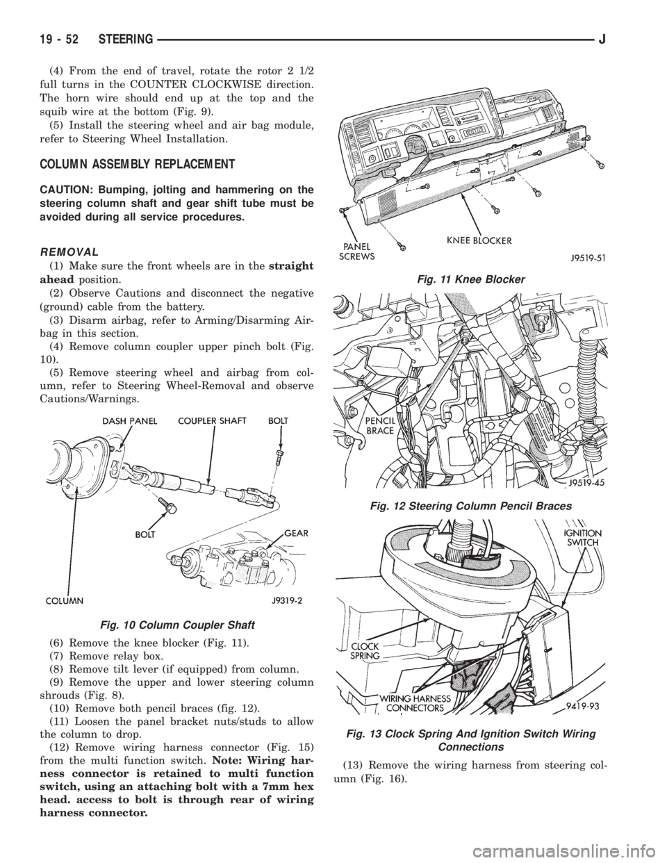
(4) Remove column coupler upper pinch bolt (Fig.
10).
(5) Remove steering wheel and airbag from col-
umn, refer to Steering Wheel-Removal and observe
Cautions/Warnings.
(6) Remove the knee blocker (Fig. 11).
(7) Remove relay box.
(8) Remove tilt lever (if equipped) from column.
(9) Remove the upper and lower steering column
shrouds (Fig. 8).
(10) Remove both pencil braces (fig. 12).
(11) Loosen the panel bracket nuts/studs to allow
the column to drop.
(12) Remove wiring harness connector (Fig. 15)
from the multi function switch.Note: Wiring har-
ness connector is retained to multi function
switch, using an attaching bolt with a 7mm hex
head. access to bolt is through rear of wiring
harness connector.(13) Remove the wiring harness from steering col-
umn (Fig. 16).
Fig. 10 Column Coupler Shaft
Fig. 11 Knee Blocker
Fig. 12 Steering Column Pencil Braces
Fig. 13 Clock Spring And Ignition Switch Wiring
Connections
19 - 52 STEERINGJ