airbag JEEP CHEROKEE 1995 Service Repair Manual
[x] Cancel search | Manufacturer: JEEP, Model Year: 1995, Model line: CHEROKEE, Model: JEEP CHEROKEE 1995Pages: 2198, PDF Size: 82.83 MB
Page 344 of 2198
INSTRUMENT PANEL AND GAUGES
GROUP INDEX
INSTRUMENT PANEL AND GAUGESÐXJ...... 1INSTRUMENT PANEL AND GAUGESÐYJ..... 24
INSTRUMENT PANEL AND GAUGESÐXJ
CONTENTS
page page
DIAGNOSIS............................. 5
GENERAL INFORMATION.................. 1SERVICE PROCEDURES.................. 17
SPECIFICATIONS........................ 23
GENERAL INFORMATION
Following are general descriptions of major instru-
ment panel components. Refer to Group 8W - Wiring
Diagrams for complete circuit descriptions and dia-
grams.
INSTRUMENT PANEL
Modular instrument panel construction allows all
gauges and controls to be serviced from the front of
the panel. In addition, most instrument panel wiring
or heater and air conditioning components can be ac-
cessed without complete instrument panel removal. If
necessary, the instrument panel can be rolled-down
and removed from the vehicle as an assembly.
Removal of the instrument cluster bezel allows ac-
cess to the cluster assembly, most switches, the cli-
mate controls, and the radio. Removal of the cluster
assembly allows access to the individual gauges, illu-
mination and indicator lamp bulbs, printed circuits,
and most wiring.
Removal of the lower instrument panel allows ac-
cess to heater and air conditioning components, the
fuseblock module, the relay center, and other wiring
and electrical components. Those models equipped
with a driver's-side airbag restraint have a knee
blocker and reinforcement behind the driver's-side
lower instrument panel.
The instrument panel layout is mirror image for
left-hand and right-hand drive vehicles. In most
cases, the diagnosis and service procedures found in
this group are applicable to either vehicle. Although,most illustrations represent only the typical left-hand
drive version. Exceptions are clearly identified as
Right-Hand Drive (RHD).
INSTRUMENT CLUSTERS
Two basic instrument cluster options are offered on
XJ (Cherokee) models. One is referred to as a low-
line cluster, and the other is referred to as a high-
line cluster. Each cluster is divided into two areas:
the gauge area, and the tell-tale area. Each area is
served by a separate printed circuit and wiring con-
nector. Some variations of each cluster exist due to
optional equipment and regulatory requirements.
The low-line cluster includes the following gauges:
²fuel gauge
²speedometer/odometer.
The low-line cluster includes provisions for the fol-
lowing indicator lamps:
²anti-lock brake system lamp
²brake warning lamp
²coolant temperature warning lamp
²four-wheel drive indicator lamps
²generator warning lamp
²headlamp high beam indicator lamp
²low oil pressure warning lamp
²low washer fluid warning lamp
²malfunction indicator (Check Engine) lamp
²seat belt reminder lamp
²turn signal indicator lamps
²upshift indicator lamp.
JINSTRUMENT PANEL AND GAUGES 8E - 1
Page 398 of 2198
HORNS
CONTENTS
page page
DIAGNOSIS............................. 2
GENERAL INFORMATION.................. 1SERVICE PROCEDURES................... 3
SPECIFICATIONS......................... 5
GENERAL INFORMATION
Following are general descriptions of the major
components in the XJ (Cherokee)/YJ (Wrangler) horn
systems. Refer to Group 8W - Wiring Diagrams for
complete circuit descriptions and diagrams.
HORN SWITCH
XJ
Two horn switches are installed in the steering
wheel, one on each side of the center-mounted driv-
er's airbag module. When either switch is depressed
it completes a circuit to ground for the coil side of the
horn relay. The steering wheel and steering column
must be properly grounded for the horn switches to
function. The horn switches are only serviced as a set
with their wiring. If either switch should fail, both
switches must be replaced.
YJ
A single switch is installed in the center of the
steering wheel, directly under the horn button. When
the horn button is depressed the switch completes a
circuit to ground for the coil side of the horn relay.
The steering wheel and steering column must be
properly grounded for the horn switch to function.
The horn switch is available for service.
HORN RELAY
On XJ models, the horn relay is a mini-relay in-
stalled in the relay center, which is mounted to the
lower instrument panel reinforcement inboard of thesteering column. On YJ models, the horn relay is a
ISO relay installed in the Power Distribution Center
(PDC) near the battery tray. Refer to underside of
PDC cover for relay identification.
One side of the horn relay electromagnetic coil re-
ceives battery voltage at all times. When a horn
switch is depressed, the other side of the relay coil is
grounded. The energized relay coil causes the nor-
mally open relay contacts to close, providing battery
voltage to the horn.
If a problem is encountered with a continuously
sounding horn, it can usually be quickly resolved by
removing the horn relay until further diagnosis is
completed.
HORNS
On YJ models, a standard single, low-note, dia-
phragm-type horn is mounted and grounded to the
left inner fender shield under the hood. Dual horns
are standard equipment on XJ models. The high-note
diaphragm-type horn is mounted and grounded to
the left radiator closure panel brace behind the front
bumper. The low-note diaphragm-type horn is con-
nected in parallel with the high-note horn and is
mounted and grounded to the right radiator closure
panel brace behind the front bumper.
On XJ models, a cadmium-plated screw is
used to attach the horns to the body. Do not
substitute other types of screws as they may be-
come corroded and cause a loss of ground.
JHORNS 8G - 1
Page 399 of 2198
DIAGNOSIS
WARNING: ON VEHICLES EQUIPPED WITH AN AIR-
BAG, REFER TO GROUP 8M - RESTRAINT SYS-
TEMS BEFORE ATTEMPTING STEERING WHEEL
COMPONENT DIAGNOSIS OR SERVICE. FAILURE
TO TAKE PROPER PRECAUTIONS COULD RESULT
IN ACCIDENTAL AIRBAG DEPLOYMENT AND POS-
SIBLE PERSONAL INJURY.
(1) Inspect fuses (F8 and F16 in PDC on YJ)(11 in
fuseblock module and F14 in PDC on XJ). Replace
fuses, as required.
(2) Remove the horn relay (in the PDC on YJ)(in
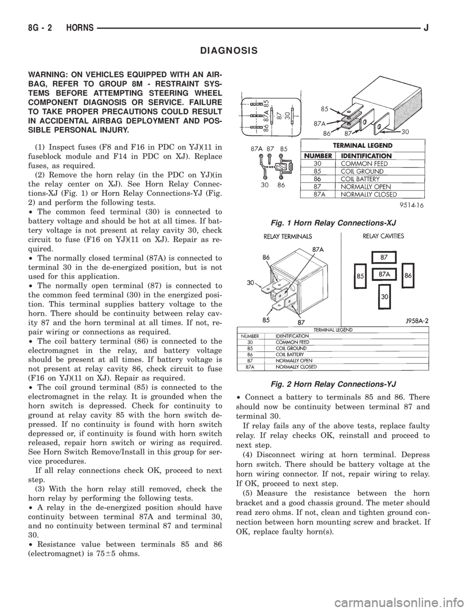
the relay center on XJ). See Horn Relay Connec-
tions-XJ (Fig. 1) or Horn Relay Connections-YJ (Fig.
2) and perform the following tests.
²The common feed terminal (30) is connected to
battery voltage and should be hot at all times. If bat-
tery voltage is not present at relay cavity 30, check
circuit to fuse (F16 on YJ)(11 on XJ). Repair as re-
quired.
²The normally closed terminal (87A) is connected to
terminal 30 in the de-energized position, but is not
used for this application.
²The normally open terminal (87) is connected to
the common feed terminal (30) in the energized posi-
tion. This terminal supplies battery voltage to the
horn. There should be continuity between relay cav-
ity 87 and the horn terminal at all times. If not, re-
pair wiring or connections as required.
²The coil battery terminal (86) is connected to the
electromagnet in the relay, and battery voltage
should be present at all times. If battery voltage is
not present at relay cavity 86, check circuit to fuse
(F16 on YJ)(11 on XJ). Repair as required.
²The coil ground terminal (85) is connected to the
electromagnet in the relay. It is grounded when the
horn switch is depressed. Check for continuity to
ground at relay cavity 85 with the horn switch de-
pressed. If no continuity is found with horn switch
depressed or, if continuity is found with horn switch
released, repair horn switch or wiring as required.
See Horn Switch Remove/Install in this group for ser-
vice procedures.
If all relay connections check OK, proceed to next
step.
(3) With the horn relay still removed, check the
horn relay by performing the following tests.
²A relay in the de-energized position should have
continuity between terminal 87A and terminal 30,
and no continuity between terminal 87 and terminal
30.
²Resistance value between terminals 85 and 86
(electromagnet) is 7565 ohms.²Connect a battery to terminals 85 and 86. There
should now be continuity between terminal 87 and
terminal 30.
If relay fails any of the above tests, replace faulty
relay. If relay checks OK, reinstall and proceed to
next step.
(4) Disconnect wiring at horn terminal. Depress
horn switch. There should be battery voltage at the
horn wiring connector. If not, repair wiring to relay.
If OK, proceed to next step.
(5) Measure the resistance between the horn
bracket and a good chassis ground. The meter should
read zero ohms. If not, clean and tighten ground con-
nection between horn mounting screw and bracket. If
OK, replace faulty horn(s).
Fig. 1 Horn Relay Connections-XJ
Fig. 2 Horn Relay Connections-YJ
8G - 2 HORNSJ
Page 400 of 2198
SERVICE PROCEDURES
HORN REMOVE/INSTALL
XJ
(1) Raise and support the vehicle.
(2) Remove the front underbody splash shield.
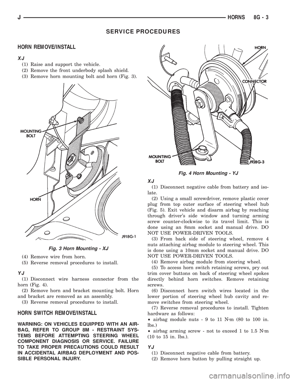
(3) Remove horn mounting bolt and horn (Fig. 3).
(4) Remove wire from horn.
(5) Reverse removal procedures to install.
YJ
(1) Disconnect wire harness connector from the
horn (Fig. 4).
(2) Remove horn and bracket mounting bolt. Horn
and bracket are removed as an assembly.
(3) Reverse removal procedures to install.
HORN SWITCH REMOVE/INSTALL
WARNING: ON VEHICLES EQUIPPED WITH AN AIR-
BAG, REFER TO GROUP 8M - RESTRAINT SYS-
TEMS BEFORE ATTEMPTING STEERING WHEEL
COMPONENT DIAGNOSIS OR SERVICE. FAILURE
TO TAKE PROPER PRECAUTIONS COULD RESULT
IN ACCIDENTAL AIRBAG DEPLOYMENT AND POS-
SIBLE PERSONAL INJURY.
XJ
(1) Disconnect negative cable from battery and iso-
late.
(2) Using a small screwdriver, remove plastic cover
plug from top outer surface of steering wheel hub
(Fig. 5). Exit vehicle and disarm airbag by reaching
through driver's side window and turning arming
screw counter-clockwise to its travel limit. This is
done using an 8mm socket and manual drive. DO
NOT USE POWER-DRIVEN TOOLS.
(3) From back side of steering wheel, remove 4
nuts attaching airbag module to steering wheel. This
is done using a 10mm socket and manual drive. DO
NOT USE POWER-DRIVEN TOOLS.
(4) Remove airbag module from steering wheel.
(5) To access horn switch retaining screws, pry out
trim cover buttons on back of steering wheel spokes
directly behind horn switches. Remove retaining
screws.
(6) Disconnect horn switch wires located in the
lower portion of steering wheel hub cavity and re-
move switches from steering wheel.
(7) Reverse removal procedures to install. Tighten
hardware as follows:
²airbag module nuts-9to11Nzm (80 to 100 in.
lbs.)
²airbag arming screw - not to exceed 1 to 1.5 Nzm
(10 to 15 in. lbs.).
YJ
(1) Disconnect negative cable from battery.
(2) Remove horn button by pulling straight up.
Fig. 3 Horn Mounting - XJ
Fig. 4 Horn Mounting - YJ
JHORNS 8G - 3
Page 401 of 2198
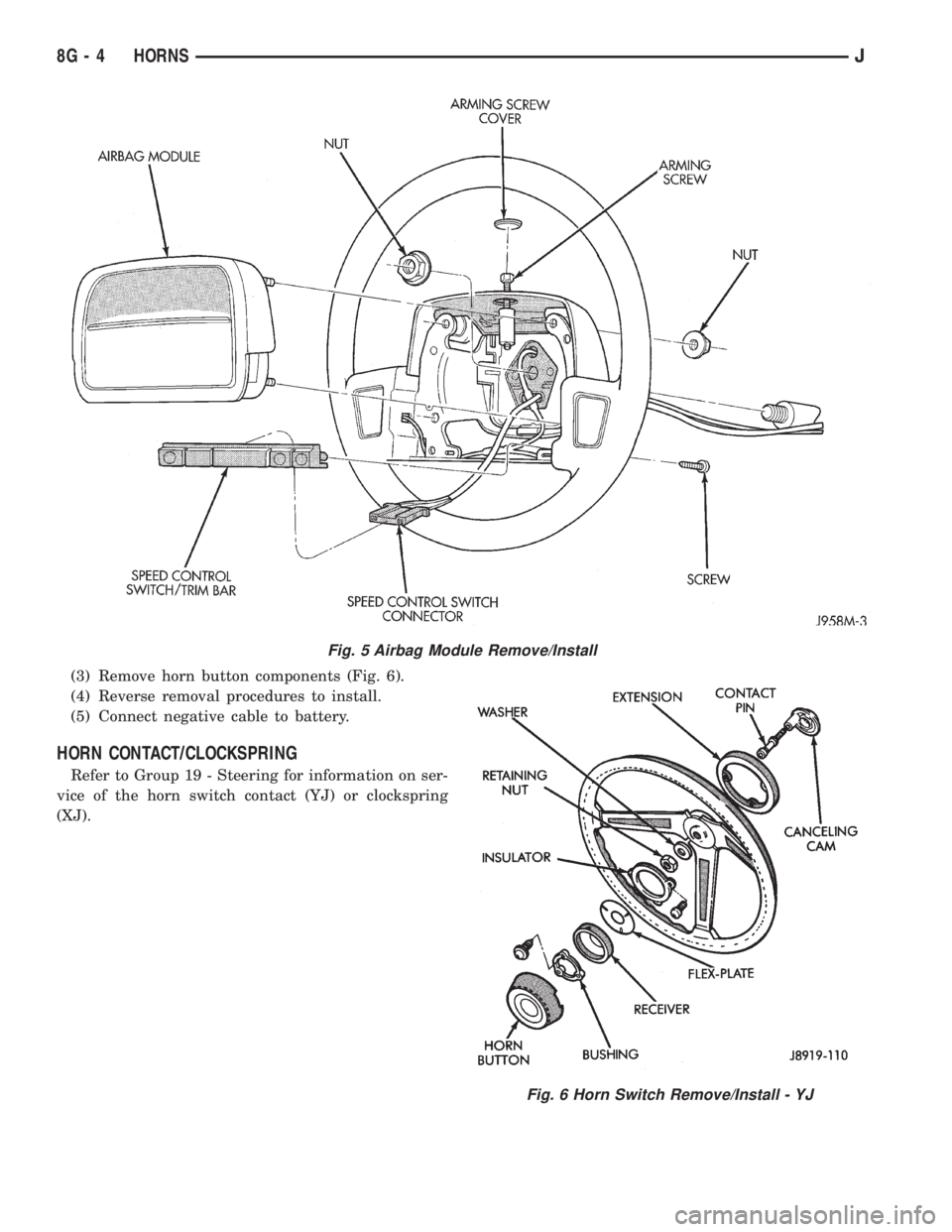
(3) Remove horn button components (Fig. 6).
(4) Reverse removal procedures to install.
(5) Connect negative cable to battery.
HORN CONTACT/CLOCKSPRING
Refer to Group 19 - Steering for information on ser-
vice of the horn switch contact (YJ) or clockspring
(XJ).
Fig. 5 Airbag Module Remove/Install
Fig. 6 Horn Switch Remove/Install - YJ
8G - 4 HORNSJ
Page 404 of 2198
VEHICLE SPEED CONTROL SYSTEM
CONTENTS
page page
DIAGNOSIS............................. 2
GENERAL INFORMATION.................. 1SERVICE PROCEDURES................... 9
GENERAL INFORMATION
The vehicle speed control system (Fig. 1) is an
available option on all XJ (Cherokee) models. The
system is electronically controlled and vacuum oper-
ated. Following are general descriptions of the major
components in the vehicle speed control system. Re-
fer to Group 8W - Wiring Diagrams for complete cir-
cuit descriptions and diagrams.
SPEED CONTROL SERVO
The speed control servo is mounted to a bracket on
the right side inner fender shield in the engine com-
partment. The servo unit consists of a solenoid valve
body, a vacuum servo and the mounting bracket. The
PCM controls the solenoid valve body. The solenoid
valve body controls the application and release of
vacuum to the diaphragm of the vacuum servo. The
servo unit cannot be repaired and is serviced only as
a complete assembly.
SPEED CONTROL SWITCH
The speed control switch module is mounted to the
center of the steering wheel below the driver's airbag
module. The PCM monitors the state of the speed
control switches. The individual switches are labeled:
OFF/ON, RESUME/ACCEL, SET/COAST. Refer to
the owner's manual for more information on speed
control switch functions and setting procedures. The
individual switches cannot be repaired. If one switch
fails, the entire switch module must be replaced.
STOP LAMP SWITCH
Vehicles with the speed control option use a dual
function stop lamp switch. The switch is mounted in
the same location as the conventional stop lamp
switch, on the brake pedal mounting bracket under
the instrument panel. The PCM monitors the state of
the dual function stop lamp switch. Refer to Group 5
- Brakes for more information on stop lamp switch
service and adjustment procedures.
SERVO CABLE
The speed control servo cable is connected betweenthe speed control vacuum servo diaphragm and the
throttle control linkage. This cable causes the throt-
tle control linkage to open or close the throttle valve
in response to movement of the vacuum servo dia-
phragm.
POWERTRAIN CONTROL MODULE
The speed control electronic control circuitry is in-
tegrated into the Powertrain Control Module (PCM).
The PCM is located in the engine compartment on
the left side inner fender shield. The PCM speed con-
trol functions are monitored by the On-Board Diag-
nostics (OBD). All OBD-sensed systems are
monitored by the PCM. Each monitored circuit is as-
signed a Diagnostic Trouble Code (DTC). The PCM
will store a DTC in electronic memory for any failure
it detects. See Using On-Board Diagnostic System in
this group for more information. The PCM cannot be
repaired and must be replaced if faulty.
VACUUM RESERVOIR
The vacuum reservoir is mounted behind the left
end of the front bumper bar. The reservoir contains a
one-way check valve to trap engine vacuum in the
reservoir. When engine vacuum drops, as in climbing
a grade while driving, the reservoir supplies the vac-
uum needed to maintain proper speed control opera-
tion. The vacuum reservoir cannot be repaired and
must be replaced if faulty.
VEHICLE SPEED SENSOR
The Vehicle Speed Sensor (VSS) is a pulse genera-
tor mounted to an adapter near the transmission
(two-wheel drive) or transfer case (four-wheel drive)
output shaft. The sensor is driven through the
adapter by a speedometer pinion gear. The VSS pulse
signal to the speedometer/odometer is monitored by
the PCM speed control circuitry to determine vehicle
speed and to maintain speed control set speed. Refer
to the appropriate Powertrain Diagnostic Procedures
manual for testing of this component. Refer to Group
14 - Fuel System for service of this component.
JVEHICLE SPEED CONTROL SYSTEM 8H - 1
Page 409 of 2198
SPEED CONTROL SWITCH
WARNING: ON VEHICLES EQUIPPED WITH AN AIR-
BAG, REFER TO GROUP 8M - RESTRAINT SYS-
TEMS BEFORE ATTEMPTING STEERING WHEEL
COMPONENT DIAGNOSIS OR SERVICE. FAILURE
TO TAKE PROPER PRECAUTIONS COULD RESULT
IN ACCIDENTAL AIRBAG DEPLOYMENT AND POS-
SIBLE PERSONAL INJURY.
(1) Disconnect battery negative cable. Remove
speed control switch from steering wheel.
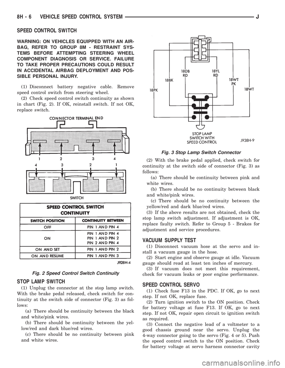
(2) Check speed control switch continuity as shown
in chart (Fig. 2). If OK, reinstall switch. If not OK,
replace switch.
STOP LAMP SWITCH
(1) Unplug the connector at the stop lamp switch.
With the brake pedal released, check switch for con-
tinuity at the switch side of connector (Fig. 3) as fol-
lows:
(a) There should be continuity between the black
and white/pink wires.
(b) There should be continuity between the yel-
low/red and dark blue/red wires.
(c) There should be no continuity between pink
and white wires.(2) With the brake pedal applied, check switch for
continuity at the switch side of connector (Fig. 3) as
follows:
(a) There should be continuity between pink and
white wires.
(b) There should be no continuity between black
and white/pink wires.
(c) There should be no continuity between the
yellow/red and dark blue/red wires.
(3) If the above results are not obtained, check the
stop lamp switch adjustment. If adjustment is OK,
replace faulty switch. Refer to Group 5 - Brakes for
adjustment and service procedures.
VACUUM SUPPLY TEST
(1) Disconnect vacuum hose at the servo and in-
stall a vacuum gauge in the hose.
(2) Start engine and observe gauge at idle. Vacuum
gauge should read at least ten inches of mercury.
(3) If vacuum does not meet this requirement,
check for vacuum leaks or poor engine performance.
SPEED CONTROL SERVO
(1) Check fuse F13 in the PDC. If OK, go to next
step. If not OK, replace fuse.
(2) Turn ignition switch to the ON position. Check
for battery voltage at fuse F13. If OK, go to next
step. If not OK, repair open circuit to ignition switch
as required.
(3) Connect the negative lead of a voltmeter to a
good chassis ground near the servo. Unplug the
4-way connector going to the servo (Fig. 4 or 5). Push
the speed control switch to the ON position. Check
for battery voltage at servo harness connector cavity
Fig. 2 Speed Control Switch Continuity
Fig. 3 Stop Lamp Switch Connector
8H - 6 VEHICLE SPEED CONTROL SYSTEMJ
Page 412 of 2198
SERVICE PROCEDURES
SPEED CONTROL SERVO REMOVE/INSTALL
(1) Disconnect battery negative cable.
(2) Disconnect vacuum hose at servo.
(3) Remove 2 nuts on servo cable sleeve.
(4) Pull speed control cable away from servo to ex-
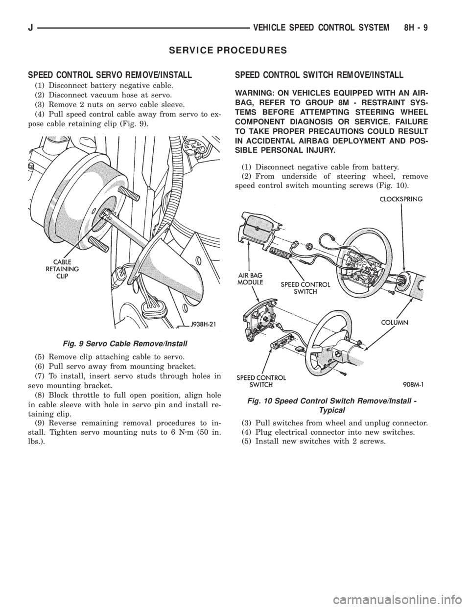
pose cable retaining clip (Fig. 9).
(5) Remove clip attaching cable to servo.
(6) Pull servo away from mounting bracket.
(7) To install, insert servo studs through holes in
sevo mounting bracket.
(8) Block throttle to full open position, align hole
in cable sleeve with hole in servo pin and install re-
taining clip.
(9) Reverse remaining removal procedures to in-
stall. Tighten servo mounting nuts to 6 Nzm (50 in.
lbs.).
SPEED CONTROL SWITCH REMOVE/INSTALL
WARNING: ON VEHICLES EQUIPPED WITH AN AIR-
BAG, REFER TO GROUP 8M - RESTRAINT SYS-
TEMS BEFORE ATTEMPTING STEERING WHEEL
COMPONENT DIAGNOSIS OR SERVICE. FAILURE
TO TAKE PROPER PRECAUTIONS COULD RESULT
IN ACCIDENTAL AIRBAG DEPLOYMENT AND POS-
SIBLE PERSONAL INJURY.
(1) Disconnect negative cable from battery.
(2) From underside of steering wheel, remove
speed control switch mounting screws (Fig. 10).
(3) Pull switches from wheel and unplug connector.
(4) Plug electrical connector into new switches.
(5) Install new switches with 2 screws.
Fig. 9 Servo Cable Remove/Install
Fig. 10 Speed Control Switch Remove/Install -
Typical
JVEHICLE SPEED CONTROL SYSTEM 8H - 9
Page 416 of 2198
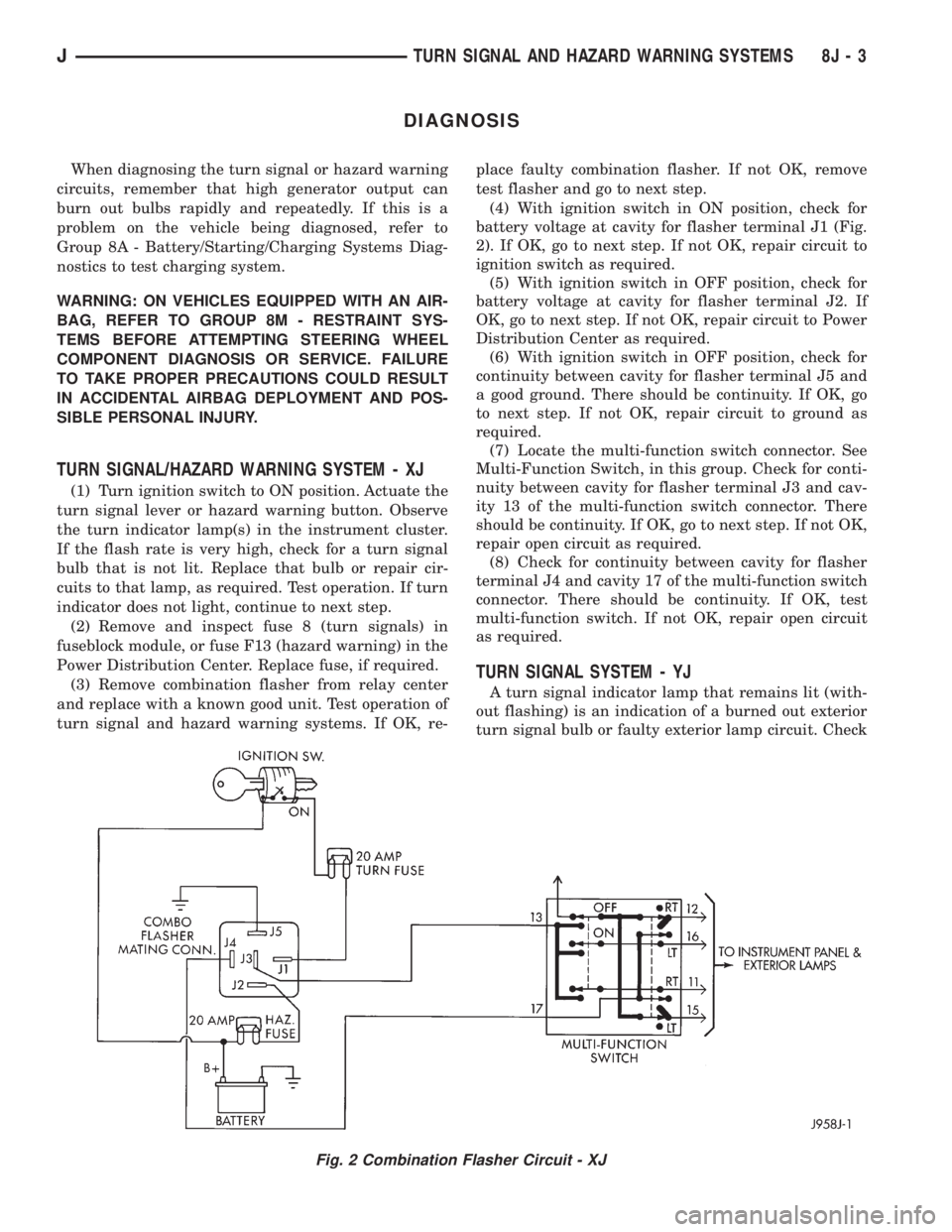
DIAGNOSIS
When diagnosing the turn signal or hazard warning
circuits, remember that high generator output can
burn out bulbs rapidly and repeatedly. If this is a
problem on the vehicle being diagnosed, refer to
Group 8A - Battery/Starting/Charging Systems Diag-
nostics to test charging system.
WARNING: ON VEHICLES EQUIPPED WITH AN AIR-
BAG, REFER TO GROUP 8M - RESTRAINT SYS-
TEMS BEFORE ATTEMPTING STEERING WHEEL
COMPONENT DIAGNOSIS OR SERVICE. FAILURE
TO TAKE PROPER PRECAUTIONS COULD RESULT
IN ACCIDENTAL AIRBAG DEPLOYMENT AND POS-
SIBLE PERSONAL INJURY.
TURN SIGNAL/HAZARD WARNING SYSTEM - XJ
(1) Turn ignition switch to ON position. Actuate the
turn signal lever or hazard warning button. Observe
the turn indicator lamp(s) in the instrument cluster.
If the flash rate is very high, check for a turn signal
bulb that is not lit. Replace that bulb or repair cir-
cuits to that lamp, as required. Test operation. If turn
indicator does not light, continue to next step.
(2) Remove and inspect fuse 8 (turn signals) in
fuseblock module, or fuse F13 (hazard warning) in the
Power Distribution Center. Replace fuse, if required.
(3) Remove combination flasher from relay center
and replace with a known good unit. Test operation of
turn signal and hazard warning systems. If OK, re-place faulty combination flasher. If not OK, remove
test flasher and go to next step.
(4) With ignition switch in ON position, check for
battery voltage at cavity for flasher terminal J1 (Fig.
2). If OK, go to next step. If not OK, repair circuit to
ignition switch as required.
(5) With ignition switch in OFF position, check for
battery voltage at cavity for flasher terminal J2. If
OK, go to next step. If not OK, repair circuit to Power
Distribution Center as required.
(6) With ignition switch in OFF position, check for
continuity between cavity for flasher terminal J5 and
a good ground. There should be continuity. If OK, go
to next step. If not OK, repair circuit to ground as
required.
(7) Locate the multi-function switch connector. See
Multi-Function Switch, in this group. Check for conti-
nuity between cavity for flasher terminal J3 and cav-
ity 13 of the multi-function switch connector. There
should be continuity. If OK, go to next step. If not OK,
repair open circuit as required.
(8) Check for continuity between cavity for flasher
terminal J4 and cavity 17 of the multi-function switch
connector. There should be continuity. If OK, test
multi-function switch. If not OK, repair open circuit
as required.
TURN SIGNAL SYSTEM - YJ
A turn signal indicator lamp that remains lit (with-
out flashing) is an indication of a burned out exterior
turn signal bulb or faulty exterior lamp circuit. Check
Fig. 2 Combination Flasher Circuit - XJ
JTURN SIGNAL AND HAZARD WARNING SYSTEMS 8J - 3
Page 418 of 2198
SERVICE PROCEDURES
WARNING: ON VEHICLES EQUIPPED WITH AN AIRBAG,
REFER TO GROUP 8M - RESTRAINT SYSTEMS BEFORE
ATTEMPTING STEERING WHEEL COMPONENT DIAGNO-
SIS OR SERVICE. FAILURE TO TAKE PROPER PRECAU-
TIONS COULD RESULT IN ACCIDENTAL AIRBAG DE-
PLOYMENT AND POSSIBLE PERSONAL INJURY.
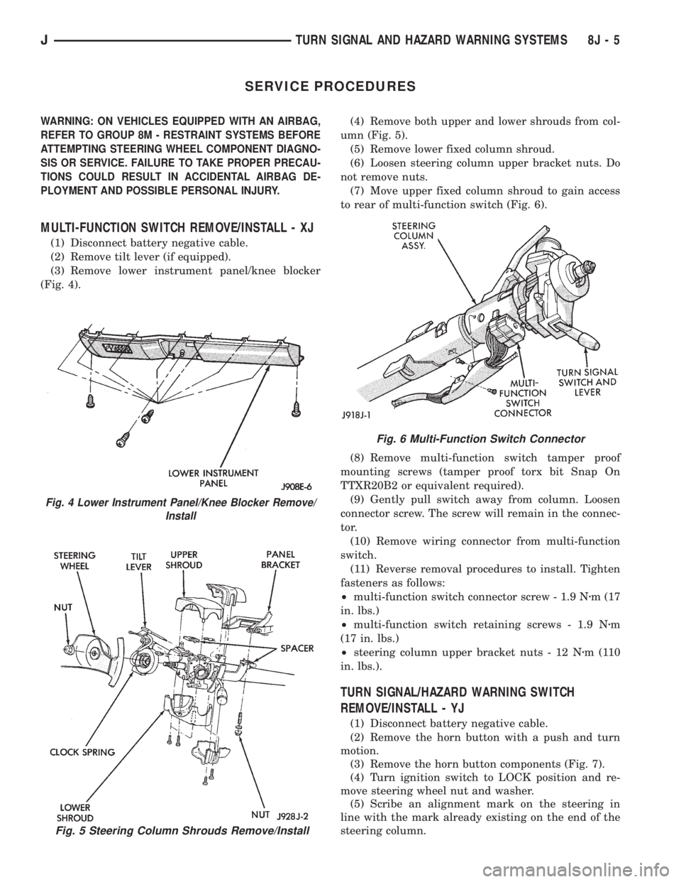
MULTI-FUNCTION SWITCH REMOVE/INSTALL - XJ
(1) Disconnect battery negative cable.
(2) Remove tilt lever (if equipped).
(3) Remove lower instrument panel/knee blocker
(Fig. 4).(4) Remove both upper and lower shrouds from col-
umn (Fig. 5).
(5) Remove lower fixed column shroud.
(6) Loosen steering column upper bracket nuts. Do
not remove nuts.
(7) Move upper fixed column shroud to gain access
to rear of multi-function switch (Fig. 6).
(8) Remove multi-function switch tamper proof
mounting screws (tamper proof torx bit Snap On
TTXR20B2 or equivalent required).
(9) Gently pull switch away from column. Loosen
connector screw. The screw will remain in the connec-
tor.
(10) Remove wiring connector from multi-function
switch.
(11) Reverse removal procedures to install. Tighten
fasteners as follows:
²multi-function switch connector screw - 1.9 Nzm (17
in. lbs.)
²multi-function switch retaining screws - 1.9 Nzm
(17 in. lbs.)
²steering column upper bracket nuts - 12 Nzm(110
in. lbs.).
TURN SIGNAL/HAZARD WARNING SWITCH
REMOVE/INSTALL - YJ
(1) Disconnect battery negative cable.
(2) Remove the horn button with a push and turn
motion.
(3) Remove the horn button components (Fig. 7).
(4) Turn ignition switch to LOCK position and re-
move steering wheel nut and washer.
(5) Scribe an alignment mark on the steering in
line with the mark already existing on the end of the
steering column.
Fig. 5 Steering Column Shrouds Remove/Install
Fig. 4 Lower Instrument Panel/Knee Blocker Remove/
Install
Fig. 6 Multi-Function Switch Connector
JTURN SIGNAL AND HAZARD WARNING SYSTEMS 8J - 5