service JEEP CHEROKEE 1995 Service Owner's Manual
[x] Cancel search | Manufacturer: JEEP, Model Year: 1995, Model line: CHEROKEE, Model: JEEP CHEROKEE 1995Pages: 2198, PDF Size: 82.83 MB
Page 46 of 2198
XJ FRONT SUSPENSION
INDEX
page page
Axle Bushing Replacement.................. 12
Coil Spring.............................. 14
Lower Suspension Arm..................... 13
Service Information........................ 11
Shock Absorber.......................... 13Spring and Shock Diagnosis................. 13
Stabilizer Bar............................ 11
Track Bar............................... 11
Upper Suspension Arm..................... 12
SERVICE INFORMATION
Periodic lubrication of the steering system and sus-
pension components is required. Refer to Group 0,
Lubrication And Maintenance for the service inter-
val.
CAUTION: Suspension components with rubber
bushings should be tightened with the vehicle at
normal height. It is important to have the springs
supporting the weight of the vehicle when the fas-
teners are torqued. If springs are not at their normal
ride position, vehicle ride comfort could be affected
and premature bushing wear may occur. Rubber
bushings must never be lubricated.
TRACK BAR
REMOVAL
(1) Raise and support the vehicle.
(2) Remove the cotter pin and nut from the ball
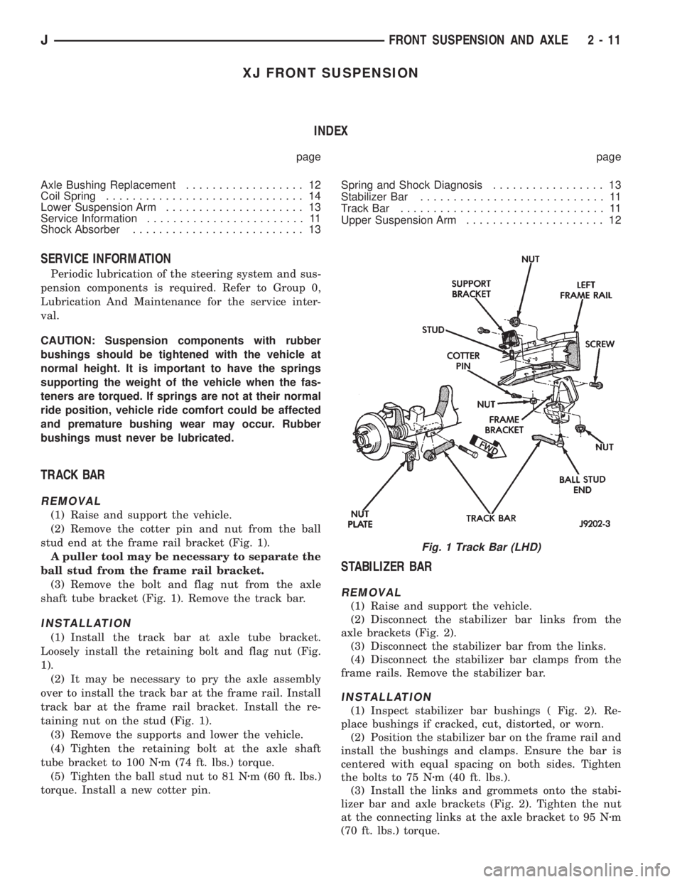
stud end at the frame rail bracket (Fig. 1).
A puller tool may be necessary to separate the
ball stud from the frame rail bracket.
(3) Remove the bolt and flag nut from the axle
shaft tube bracket (Fig. 1). Remove the track bar.
INSTALLATION
(1) Install the track bar at axle tube bracket.
Loosely install the retaining bolt and flag nut (Fig.
1).
(2) It may be necessary to pry the axle assembly
over to install the track bar at the frame rail. Install
track bar at the frame rail bracket. Install the re-
taining nut on the stud (Fig. 1).
(3) Remove the supports and lower the vehicle.
(4) Tighten the retaining bolt at the axle shaft
tube bracket to 100 Nzm (74 ft. lbs.) torque.
(5) Tighten the ball stud nut to 81 Nzm (60 ft. lbs.)
torque. Install a new cotter pin.
STABILIZER BAR
REMOVAL
(1) Raise and support the vehicle.
(2) Disconnect the stabilizer bar links from the
axle brackets (Fig. 2).
(3) Disconnect the stabilizer bar from the links.
(4) Disconnect the stabilizer bar clamps from the
frame rails. Remove the stabilizer bar.
INSTALLATION
(1) Inspect stabilizer bar bushings ( Fig. 2). Re-
place bushings if cracked, cut, distorted, or worn.
(2) Position the stabilizer bar on the frame rail and
install the bushings and clamps. Ensure the bar is
centered with equal spacing on both sides. Tighten
the bolts to 75 Nzm (40 ft. lbs.).
(3) Install the links and grommets onto the stabi-
lizer bar and axle brackets (Fig. 2). Tighten the nut
at the connecting links at the axle bracket to 95 Nzm
(70 ft. lbs.) torque.
Fig. 1 Track Bar (LHD)
JFRONT SUSPENSION AND AXLE 2 - 11
Page 50 of 2198
YJ FRONT SUSPENSION
INDEX
page page
Leaf Spring.............................. 16
Leaf Spring Eye Bushing Replacement......... 17
Service Information........................ 15
Shock Absorber.......................... 16Spring and Shock Diagnosis................. 15
Stabilizer Bar............................ 15
Track Bar............................... 15
SERVICE INFORMATION
Periodic lubrication of the steering system and sus-
pension components is required. Refer to Group 0,
Lubrication And Maintenance for the service inter-
val.
CAUTION: Suspension components with rubber
bushings should be tightened with the vehicle at
normal height. It is important to have the springs
supporting the weight of the vehicle when the fas-
teners are torqued. If springs are not at their normal
ride position, vehicle ride comfort could be affected
and premature bushing wear may occur. Rubber
bushings must never be lubricated.
TRACK BAR
REMOVAL
(1) Raise and support the vehicle.
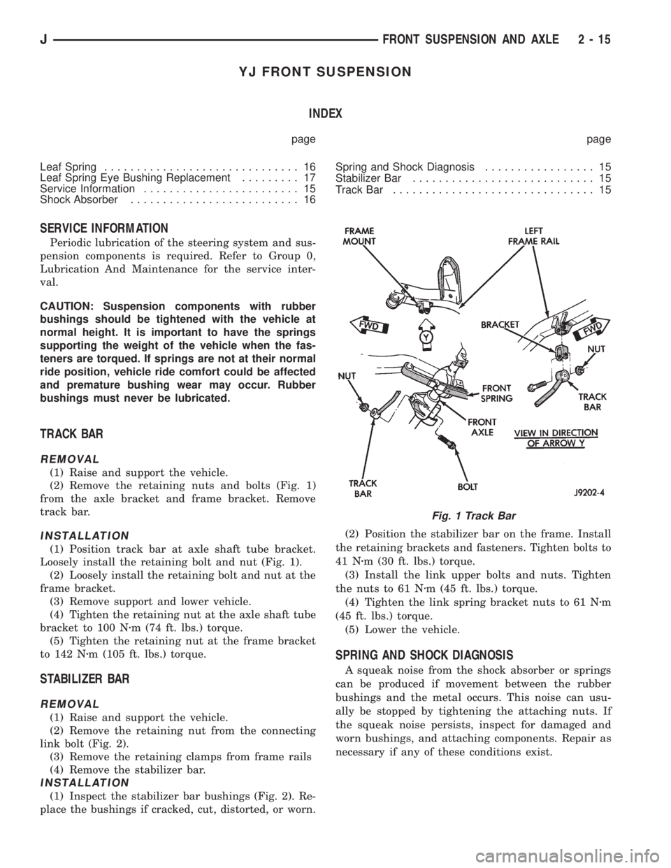
(2) Remove the retaining nuts and bolts (Fig. 1)
from the axle bracket and frame bracket. Remove
track bar.
INSTALLATION
(1) Position track bar at axle shaft tube bracket.
Loosely install the retaining bolt and nut (Fig. 1).
(2) Loosely install the retaining bolt and nut at the
frame bracket.
(3) Remove support and lower vehicle.
(4) Tighten the retaining nut at the axle shaft tube
bracket to 100 Nzm (74 ft. lbs.) torque.
(5) Tighten the retaining nut at the frame bracket
to 142 Nzm (105 ft. lbs.) torque.
STABILIZER BAR
REMOVAL
(1) Raise and support the vehicle.
(2) Remove the retaining nut from the connecting
link bolt (Fig. 2).
(3) Remove the retaining clamps from frame rails
(4) Remove the stabilizer bar.
INSTALLATION
(1) Inspect the stabilizer bar bushings (Fig. 2). Re-
place the bushings if cracked, cut, distorted, or worn.(2) Position the stabilizer bar on the frame. Install
the retaining brackets and fasteners. Tighten bolts to
41 Nzm (30 ft. lbs.) torque.
(3) Install the link upper bolts and nuts. Tighten
the nuts to 61 Nzm (45 ft. lbs.) torque.
(4) Tighten the link spring bracket nuts to 61 Nzm
(45 ft. lbs.) torque.
(5) Lower the vehicle.
SPRING AND SHOCK DIAGNOSIS
A squeak noise from the shock absorber or springs
can be produced if movement between the rubber
bushings and the metal occurs. This noise can usu-
ally be stopped by tightening the attaching nuts. If
the squeak noise persists, inspect for damaged and
worn bushings, and attaching components. Repair as
necessary if any of these conditions exist.
Fig. 1 Track Bar
JFRONT SUSPENSION AND AXLE 2 - 15
Page 53 of 2198
AXLE NOISE/VIBRATION DIAGNOSIS
INDEX
page page
Driveline Snap........................... 19
Gear and Bearing Noise.................... 18
General Information....................... 18Low Speed Knock......................... 19
Vibration................................ 19
GENERAL INFORMATION
Axle bearing problem conditions are usually caused
by:
²Insufficient or incorrect lubricant
²Foreign matter/water contamination
²Incorrect bearing preload torque adjustment
²Incorrect backlash (to tight)
When serviced, the bearings must be cleaned thor-
oughly. They should be dried with lint-free shop tow-
els.Never dry bearings with compressed air.
This will overheat them and brinell the bearing
surfaces. This will result in noisy operation af-
ter repair.
Axle gear problem conditions are usually the result
of:
²Insufficient lubrication
²Incorrect or contaminated lubricant
²Overloading (excessive engine torque) or exceeding
vehicle weight capacity
²Incorrect clearance or backlash adjustment
Insufficient lubrication is usually the result of a
housing cover leak. It can also be from worn axle
shaft or pinion gear seals. Check for cracks or porous
areas in the housing or tubes.
Using the wrong lubricant will cause overheating
and gear failure. Gear tooth cracking and bearing
spalling are indicators of this.
Axle component breakage is most often the result
of:
²Severe overloading
²Insufficient lubricant
²Incorrect lubricant
²Improperly tightened components
Overloading occurs when towing heavier than rec-
ommended loads. Component breakage can occur
when the wheels are spun excessively. Incorrect lu-
bricant quantity contributes to breakage. Loose dif-
ferential components can also cause breakage.
Incorrect bearing preload or gear backlash will not
result in component breakage. Mis-adjustment will
produce enough noise to cause service repair before a
failure occurs. If a mis-adjustment condition is not
corrected, component failure can result.
Excessive bearing preload may not be noisy. This
condition will cause high temperature which can re-
sult in bearing failure.
GEAR AND BEARING NOISE
GEAR NOISE
Axle gear noise can be caused by insufficient lubri-
cant. Incorrect backlash, tooth contact, or worn/dam-
aged gears can cause noise.
Gear noise usually happens at a specific speed
range. The range is 30 to 40 mph, or above 50 mph.
The noise can also occur during a specific type of
driving condition. These conditions are acceleration,
deceleration, coast, or constant load.
When road testing, accelerate the vehicle to the
speed range where the noise is the greatest. Shift
out-of-gear and coast through the peak-noise range.
If the noise stops or changes greatly, check for insuf-
ficient lubricant. Incorrect ring gear backlash, or
gear damage can cause noise changes.
Differential side and pinion gears can be checked
by turning the vehicle. They usually do not cause
noise in straight-ahead driving. These gears are
loaded during vehicle turns. If noise does occur dur-
ing vehicle turns, the side or pinion gears could be
worn or damaged. A worn pinion gear mate shaft can
also cause a snapping or a knocking noise.
BEARING NOISE
The axle shaft, differential and pinion gear bear-
ings can all produce noise when worn or damaged.
Bearing noise can be either a whining, or a growling
sound.
Pinion gear bearings have a constant-pitch noise.
This noise changes only with vehicle speed. Pinion
bearing noise will be higher because it rotates at a
faster rate. Drive the vehicle and load the differen-
tial. If bearing noise occurs the pinion rear bearing is
the source of the noise. If the bearing noise is heard
during a coast, front bearing is the source.
Worn, damaged differential bearings usually pro-
duce a low pitch noise. Differential bearing noise is
similar to pinion bearing. The pitch of differential
bearing noise is also constant and varies only with
vehicle speed.
2 - 18 FRONT SUSPENSION AND AXLEJ
Page 55 of 2198
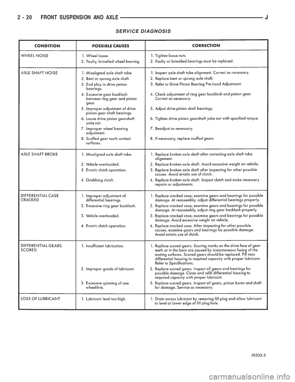
SERVICE DIAGNOSIS
2 - 20 FRONT SUSPENSION AND AXLEJ
Page 56 of 2198
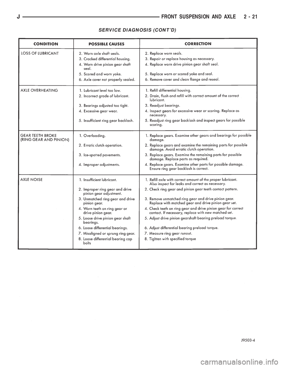
SERVICE DIAGNOSIS (CONT'D)
JFRONT SUSPENSION AND AXLE 2 - 21
Page 57 of 2198
MODEL 30 AXLE AND TUBE AXLE (2WD)
INDEX
page page
Axle Bushing Replacement.................. 34
Axle ShaftÐCardan U-Joint.................. 26
Backlash and Contact Pattern Analysis......... 45
Cleaning/Inspection........................ 37
Differential and Pinion Measurement........... 40
Differential Assembly....................... 38
Differential Disassembly.................... 35
Differential Installation...................... 44
Differential Removal....................... 34
Differential Shim Pack Measurement and
Adjustment............................ 43
Drive Axle Assembly ReplacementÐXJ Vehicles . . 23
Drive Axle Assembly ReplacementÐYJ Vehicles . . 24Final Assembly........................... 46
Hub Bearing and Axle Shaft................. 25
Information.............................. 22
Inner Axle Shaft Oil Seal Replacement......... 35
Lubricant Change......................... 23
Lubricant Specifications..................... 22
Pinion Gear Assembly/Installation............. 42
Pinion Gear Depth Information............... 39
Pinion Removal/Disassembly................. 36
Pinion Seal Replacement................... 25
Steering Knuckle and Ball Studs.............. 32
Vacuum Disconnect AxleÐYJ Vehicles......... 27
INFORMATION
The Model 30 front axles consists of a cast iron dif-
ferential housing with axle shaft tubes extending
from either side. The tubes are pressed into the dif-
ferential housing and welded.
The integral type housing, hypoid gear design has
the centerline of the pinion set above the centerline
of the ring gear.
The axle has a fitting for a vent hose used to re-
lieve internal pressure caused by lubricant vaporiza-
tion and internal expansion.
The axles are equipped with semi-floating axle
shafts, meaning that loads are supported by the hub
bearings. The axle shafts are retained by nuts at the
hub bearings. The hub bearings are bolted to the
steering knuckle at the outboard end of the axle tube
yoke. The hub bearings are serviced as an assembly.
The axles are equipped with ABS brake sensors.
The sensors are attached to the knuckle assemblies
and tone rings are pressed on the axle shaft.Use
care when removing axle shafts as NOT to dam-
age the tone wheel or the sensor.
The stamped steel cover provides a means for in-
spection and servicing the differential.
The Model 30 axle has the assembly part number
and gear ratio listed on a tag. The tag is attached to
the housing cover. Build date identification codes are
stamped on the axle shaft tube cover side.
The differential case is a one-piece design. The dif-
ferential pinion mate shaft is retained with a roll
pin. Differential bearing preload and ring gear back-
lash is adjusted by the use of shims (select thick-
ness). The shims are located between the differential
bearing cones and case. Pinion bearing preload is set
and maintained by the use of collapsible spacer.
COMMAND-TRACÐYJ VEHICLES
The Command-Trac system is a vacuum disconnect
axle. The system has a two-piece axle shaft coupled
together by a shift collar. For two-wheel drive opera-
tion, the vacuum motor and shift fork disengages the
axle shaft splines. For four-wheel drive operation, the
vacuum motor and shift fork engages the axle
splines.
SELEC-TRACÐXJ VEHICLES
The Selec-Trac system is a non-disconnect axle.
Shifting from two-wheel to four-wheel drive is done
at the transfer case.
For XJ vehicles equipped withSelec-Tracand
ABS brake system, refer to Group 5ÐBrakes for ad-
ditional service information.
LUBRICANT SPECIFICATIONS
Multi-purpose, hypoid gear lubricant should be
used for Model 30 axles. The lubricant should have
MIL-L-2105C and API GL 5 quality specifications.
MOPARtHypoid Gear Lubricant conforms to both of
these specifications.
²The factory fill for the Model 30 axle is SAE Ther-
mally Stable 80W-90 gear lubricant.Do not use
heavier weight lubricant, this will cause axle
engagement difficulties.
²The factory installed lubricant quantity for the
NON-DISCONNECT TYPE AXLE is 1.48 L (3.13
pts.).
²The factory installed lubricant quantity for the
VACUUM-DISCONNECT TYPE AXLE is 1.65 L (3.76
pts.).
Refer to Group 0, Lubrication and Maintenance for
additional information regarding temperature range,
viscosity and fluid level.
2 - 22 FRONT SUSPENSION AND AXLEJ
Page 61 of 2198

INSTALLATION
(1) Thoroughly clean the axle shaft (Fig. 6) and ap-
ply a thin film of Mopar Wheel Bearing Grease to the
shaft splines, seal contact surface, hub bore.
(2) Install the axle shaft into the housing and dif-
ferential side gears. Avoid damaging the axle shaft
oil seals in the differential.
(3) Install the hub bearing and brake dust shield
to the knuckle.
(4) Install the hub to knuckle bolts and tighten to
102 Nzm (75 ft. lbs.) torque.
(5) Install the hub washer and nut. Tighten the
hub nut to 237 Nzm (175 ft. lbs.) torque. Install the
nut retainer and a new cotter pin (Fig. 6).
(6) Install the brake components, refer to Group 5,
Brakes.
(7) Install the wheel and tire assembly.
(8) Remove support and lower the vehicle.
AXLE SHAFTÐCARDAN U-JOINT
DISASSEMBLY
Single cardan U-joints are not serviceable. If defec-
tive, they must be replaced as a unit. If the bearings,
seals, spider or bearing caps are damaged or worn,
replace the complete U-joint.
CAUTION: Clamp only the forged portion of the
yoke in the vise. Also, to avoid distorting the yoke,
do not over tighten the vise jaws.
(1) Remove the bearing cap retaining snap rings
(Fig. 7).
It can be helpful to saturate the bearing caps
with penetrating oil prior to removal.(2) Locate a socket that is larger in diameter than
the bearing cap. Place the socket (receiver) against
the yoke and around the perimeter of the bearing cap
to be removed. Locate a socket that is smaller in di-
ameter than the bearing cap. Place the socket (driv-
er) against the opposite bearing cap. Position the
yoke with the sockets in a vise (Fig. 8).
(3) Compress the vise jaws to force the bearing cap
into the larger socket (receiver).
(4) Release the vise jaws. Remove the sockets and
bearing cap that was partially forced out of the yoke.
(5) Repeat the above procedure for the remaining
bearing cap.
Fig. 6 Hub, Knuckle and Axle Shaft
Fig. 7 Axle Shaft Outer U-Joint
2 - 26 FRONT SUSPENSION AND AXLEJ
Page 66 of 2198
SHIFT MOTORÐREMOVAL/DISASSEMBLY
(1) Disconnect the vacuum and wiring connector
from the shift housing.
(2) Remove indicator switch.
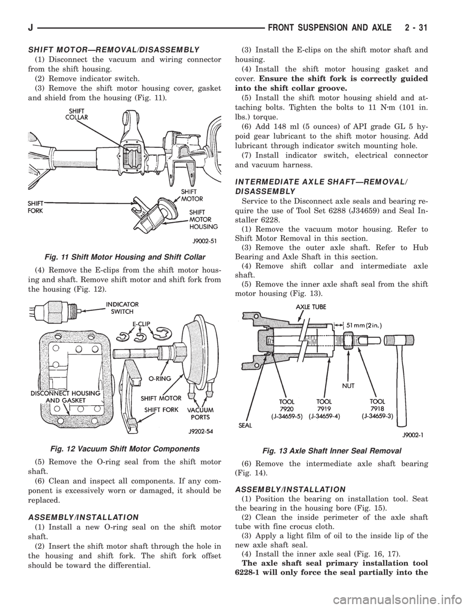
(3) Remove the shift motor housing cover, gasket
and shield from the housing (Fig. 11).
(4) Remove the E-clips from the shift motor hous-
ing and shaft. Remove shift motor and shift fork from
the housing (Fig. 12).
(5) Remove the O-ring seal from the shift motor
shaft.
(6) Clean and inspect all components. If any com-
ponent is excessively worn or damaged, it should be
replaced.
ASSEMBLY/INSTALLATION
(1) Install a new O-ring seal on the shift motor
shaft.
(2) Insert the shift motor shaft through the hole in
the housing and shift fork. The shift fork offset
should be toward the differential.(3) Install the E-clips on the shift motor shaft and
housing.
(4) Install the shift motor housing gasket and
cover.Ensure the shift fork is correctly guided
into the shift collar groove.
(5) Install the shift motor housing shield and at-
taching bolts. Tighten the bolts to 11 Nzm (101 in.
lbs.) torque.
(6) Add 148 ml (5 ounces) of API grade GL 5 hy-
poid gear lubricant to the shift motor housing. Add
lubricant through indicator switch mounting hole.
(7) Install indicator switch, electrical connector
and vacuum harness.
INTERMEDIATE AXLE SHAFTÐREMOVAL/
DISASSEMBLY
Service to the Disconnect axle seals and bearing re-
quire the use of Tool Set 6288 (J34659) and Seal In-
staller 6228.
(1) Remove the vacuum motor housing. Refer to
Shift Motor Removal in this section.
(3) Remove the outer axle shaft. Refer to Hub
Bearing and Axle Shaft in this section.
(4) Remove shift collar and intermediate axle
shaft.
(5) Remove the inner axle shaft seal from the shift
motor housing (Fig. 13).
(6) Remove the intermediate axle shaft bearing
(Fig. 14).
ASSEMBLY/INSTALLATION
(1) Position the bearing on installation tool. Seat
the bearing in the housing bore (Fig. 15).
(2) Clean the inside perimeter of the axle shaft
tube with fine crocus cloth.
(3) Apply a light film of oil to the inside lip of the
new axle shaft seal.
(4) Install the inner axle seal (Fig. 16, 17).
The axle shaft seal primary installation tool
6228-1 will only force the seal partially into the
Fig. 11 Shift Motor Housing and Shift Collar
Fig. 12 Vacuum Shift Motor ComponentsFig. 13 Axle Shaft Inner Seal Removal
JFRONT SUSPENSION AND AXLE 2 - 31
Page 67 of 2198
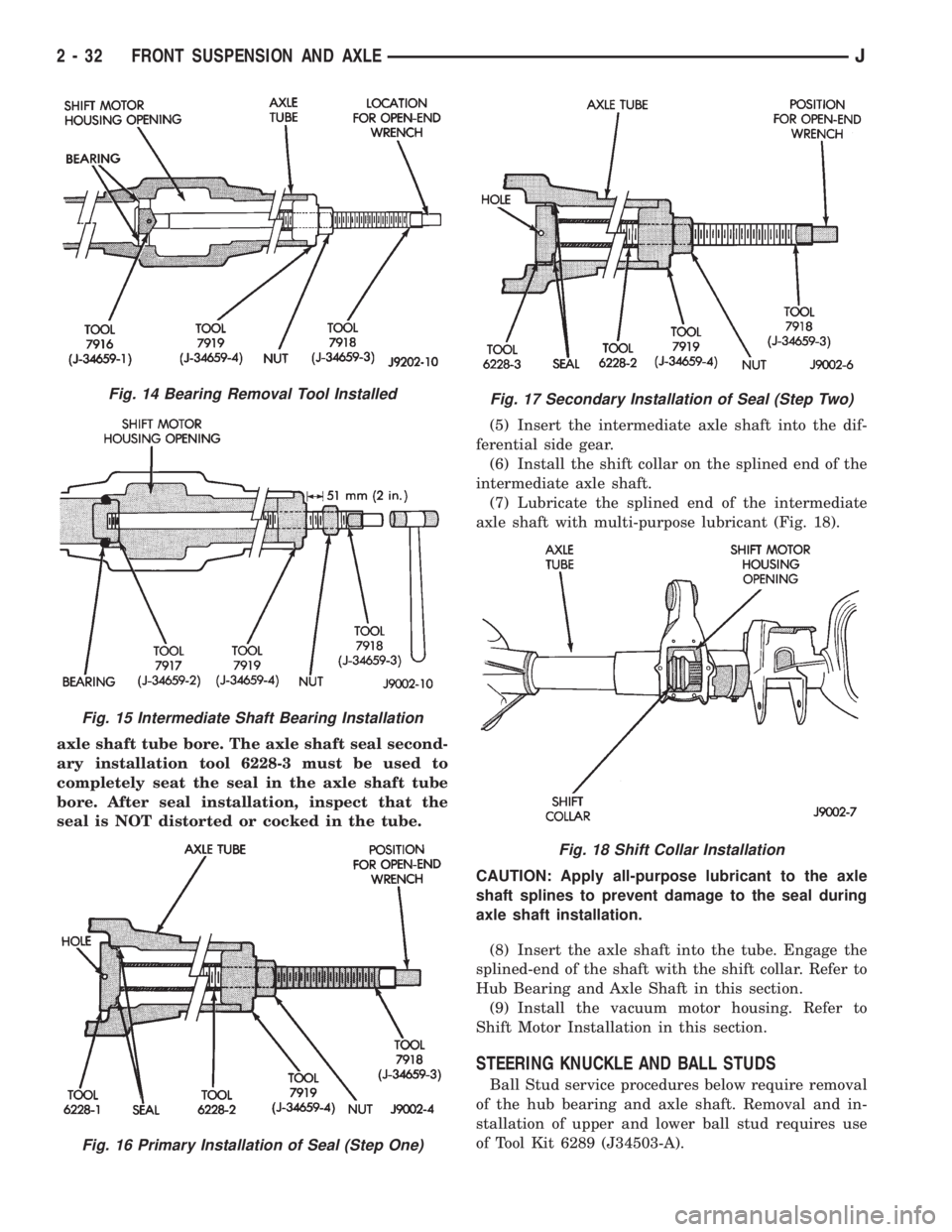
axle shaft tube bore. The axle shaft seal second-
ary installation tool 6228-3 must be used to
completely seat the seal in the axle shaft tube
bore. After seal installation, inspect that the
seal is NOT distorted or cocked in the tube.(5) Insert the intermediate axle shaft into the dif-
ferential side gear.
(6) Install the shift collar on the splined end of the
intermediate axle shaft.
(7) Lubricate the splined end of the intermediate
axle shaft with multi-purpose lubricant (Fig. 18).
CAUTION: Apply all-purpose lubricant to the axle
shaft splines to prevent damage to the seal during
axle shaft installation.
(8) Insert the axle shaft into the tube. Engage the
splined-end of the shaft with the shift collar. Refer to
Hub Bearing and Axle Shaft in this section.
(9) Install the vacuum motor housing. Refer to
Shift Motor Installation in this section.
STEERING KNUCKLE AND BALL STUDS
Ball Stud service procedures below require removal
of the hub bearing and axle shaft. Removal and in-
stallation of upper and lower ball stud requires use
of Tool Kit 6289 (J34503-A).
Fig. 14 Bearing Removal Tool Installed
Fig. 15 Intermediate Shaft Bearing Installation
Fig. 16 Primary Installation of Seal (Step One)
Fig. 17 Secondary Installation of Seal (Step Two)
Fig. 18 Shift Collar Installation
2 - 32 FRONT SUSPENSION AND AXLEJ
Page 69 of 2198
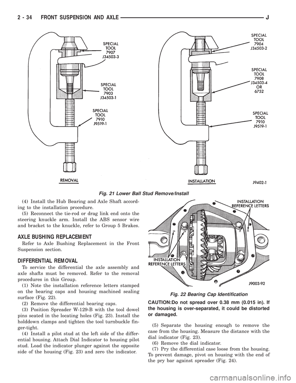
(4) Install the Hub Bearing and Axle Shaft accord-
ing to the installation procedure.
(5) Reconnect the tie-rod or drag link end onto the
steering knuckle arm. Install the ABS sensor wire
and bracket to the knuckle, refer to Group 5 Brakes.
AXLE BUSHING REPLACEMENT
Refer to Axle Bushing Replacement in the Front
Suspension section.
DIFFERENTIAL REMOVAL
To service the differential the axle assembly and
axle shafts must be removed. Refer to the removal
procedures in this Group.
(1) Note the installation reference letters stamped
on the bearing caps and housing machined sealing
surface (Fig. 22).
(2) Remove the differential bearing caps.
(3) Position Spreader W-129-B with the tool dowel
pins seated in the locating holes (Fig. 23). Install the
holddown clamps and tighten the tool turnbuckle fin-
ger-tight.
(4) Install a pilot stud at the left side of the differ-
ential housing. Attach Dial Indicator to housing pilot
stud. Load the indicator plunger against the opposite
side of the housing (Fig. 23) and zero the indicator.CAUTION:Do not spread over 0.38 mm (0.015 in). If
the housing is over-separated, it could be distorted
or damaged.
(5) Separate the housing enough to remove the
case from the housing. Measure the distance with the
dial indicator (Fig. 23).
(6) Remove the dial indicator.
(7) Pry the differential case loose from the housing.
To prevent damage, pivot on housing with the end of
the pry bar against spreader (Fig. 24).
Fig. 21 Lower Ball Stud Remove/Install
Fig. 22 Bearing Cap Identification
2 - 34 FRONT SUSPENSION AND AXLEJ