ABS JEEP CHEROKEE 1995 Service Repair Manual
[x] Cancel search | Manufacturer: JEEP, Model Year: 1995, Model line: CHEROKEE, Model: JEEP CHEROKEE 1995Pages: 2198, PDF Size: 82.83 MB
Page 12 of 2198
²Do not allow passengers to ride in a vehicle being
towed.
²Always observe state and local laws regarding tow-
ing regulations.²Do not tow a vehicle in a manner that could jeop-
ardize the safety of the operator, pedestrians or other
motorists.
²Do not attach tow chains, T-hooks, J-hooks, or a
tow sling to a bumper, steering linkage, drive shafts
or a non-reinforced frame hole.
GROUND CLEARANCE AND RAMP ANGLE
GROUND CLEARANCE
CAUTION: If vehicle is towed with wheels removed,
install lug nuts to retain brake drums.
A towed vehicle should be raised until lifted wheels
are a minimum 100 mm (4 in) from the ground. Be
sure there is adequate ground clearance at the oppo-
site end of the vehicle, especially when towing over
rough terrain or steep rises in the road. If necessary,
remove the wheels from the lifted end of the vehicle
and lower the vehicle closer to the ground, to in-
crease the ground clearance at the opposite end of
the vehicle. Install lug nuts on wheel attaching studs
to retain brake drums.
FLAT-BED TOWING RAMP ANGLE
If a vehicle with flat-bed towing equipment is used,
the approach ramp angle should not exceed 15 de-
grees.
TWO-WHEEL-DRIVE VEHICLE TOWINGÐXJ
Chrysler Corporation recommends that a vehicle be
towed with the rear end lifted, whenever possible.
TOWING-REAR END LIFTED (SLING-TYPE)
CAUTION: Do not use steering column lock to se-
cure steering wheel during towing operation.
2WD XJ vehicles can be towed with the front
wheels on the surface for extended distances at
speeds not exceeding 48 km/h (30 mph).
(1) Attach J-hooks around the axle shaft tube out-
board of the shock absorber.
(2) Place the sling crossbar under and forward of
the bumper.
(3) Attach safety chains around the frame rails.
(4) Turn the ignition switch to the OFF position to
unlock the steering wheel.
(5) Secure steering wheel in the straight ahead po-
sition with a clamp device designed for towing.
(6) Verify that steering components are in good
condition.
(7) Shift the transmission to NEUTRAL.
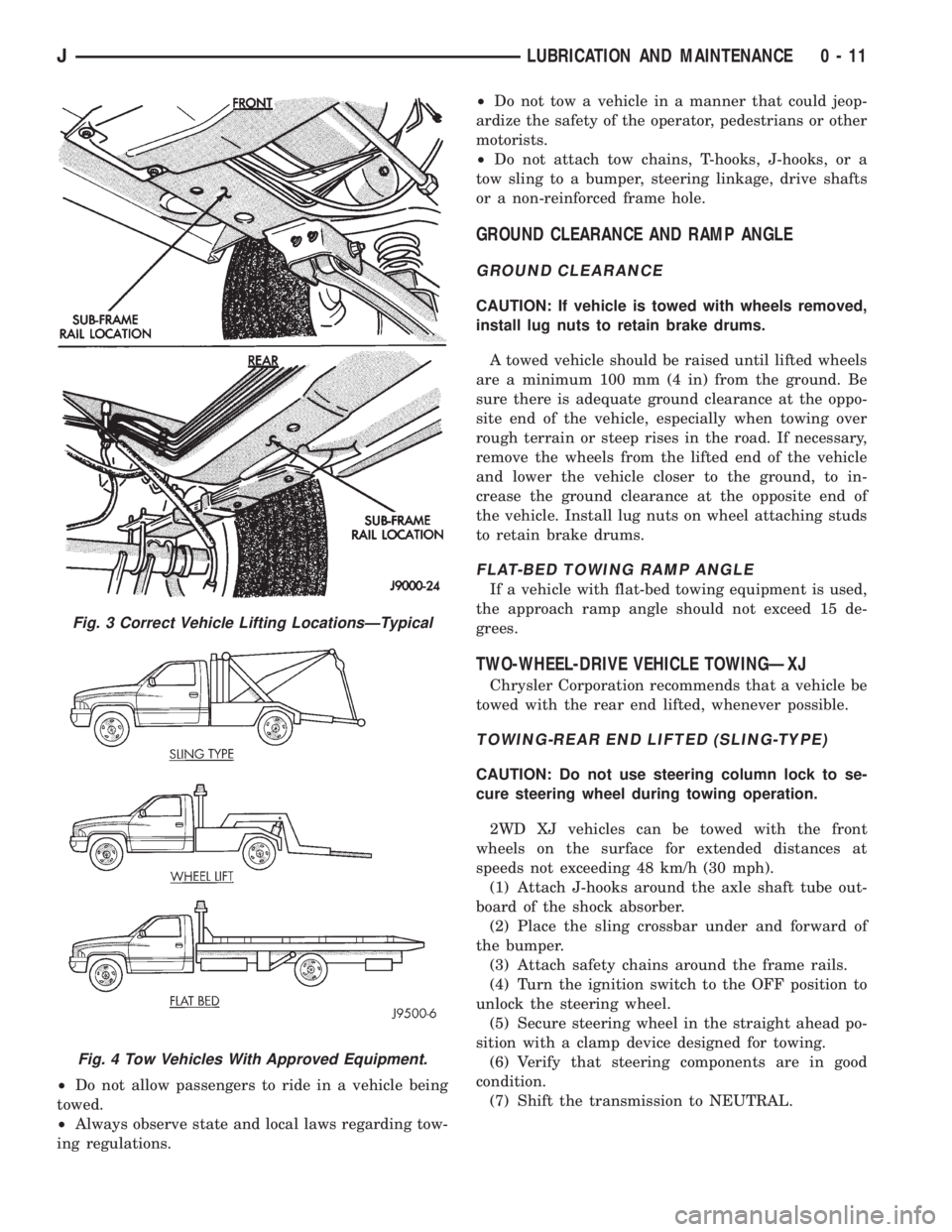
Fig. 3 Correct Vehicle Lifting LocationsÐTypical
Fig. 4 Tow Vehicles With Approved Equipment.
JLUBRICATION AND MAINTENANCE 0 - 11
Page 13 of 2198
TOWING-FRONT END LIFTED (SLING-TYPE)
CAUTION: Many vehicles are equipped with air
dams, spoilers, and/or ground effect panels. To
avoid component damage, a wheel-lift towing vehi-
cle or a flat-bed hauling vehicle is recommended.
If a 2WD XJ vehicle cannot be towed with the rear
wheels lifted, it can be towed with the front wheels
lifted.
(1) Attach a J-hook to the disabled vehicle at the
left side of the axle.
(2) Position the sling crossbar close to the J-hook
and below the front bumper.
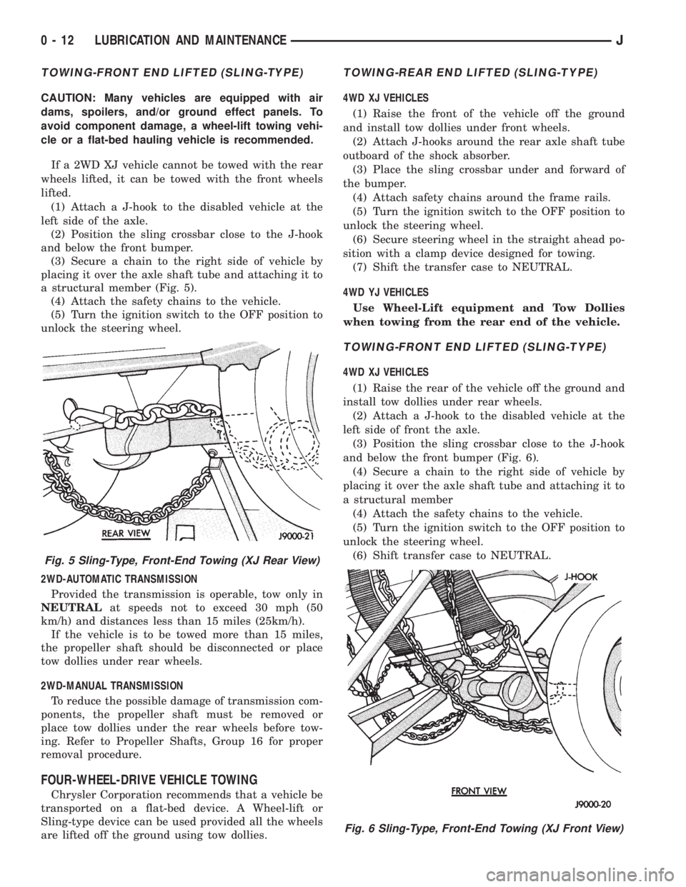
(3) Secure a chain to the right side of vehicle by
placing it over the axle shaft tube and attaching it to
a structural member (Fig. 5).
(4) Attach the safety chains to the vehicle.
(5) Turn the ignition switch to the OFF position to
unlock the steering wheel.
2WD-AUTOMATIC TRANSMISSION
Provided the transmission is operable, tow only in
NEUTRALat speeds not to exceed 30 mph (50
km/h) and distances less than 15 miles (25km/h).
If the vehicle is to be towed more than 15 miles,
the propeller shaft should be disconnected or place
tow dollies under rear wheels.
2WD-MANUAL TRANSMISSION
To reduce the possible damage of transmission com-
ponents, the propeller shaft must be removed or
place tow dollies under the rear wheels before tow-
ing. Refer to Propeller Shafts, Group 16 for proper
removal procedure.
FOUR-WHEEL-DRIVE VEHICLE TOWING
Chrysler Corporation recommends that a vehicle be
transported on a flat-bed device. A Wheel-lift or
Sling-type device can be used provided all the wheels
are lifted off the ground using tow dollies.
TOWING-REAR END LIFTED (SLING-TYPE)
4WD XJ VEHICLES
(1) Raise the front of the vehicle off the ground
and install tow dollies under front wheels.
(2) Attach J-hooks around the rear axle shaft tube
outboard of the shock absorber.
(3) Place the sling crossbar under and forward of
the bumper.
(4) Attach safety chains around the frame rails.
(5) Turn the ignition switch to the OFF position to
unlock the steering wheel.
(6) Secure steering wheel in the straight ahead po-
sition with a clamp device designed for towing.
(7) Shift the transfer case to NEUTRAL.
4WD YJ VEHICLES
Use Wheel-Lift equipment and Tow Dollies
when towing from the rear end of the vehicle.
TOWING-FRONT END LIFTED (SLING-TYPE)
4WD XJ VEHICLES
(1) Raise the rear of the vehicle off the ground and
install tow dollies under rear wheels.
(2) Attach a J-hook to the disabled vehicle at the
left side of front the axle.
(3) Position the sling crossbar close to the J-hook
and below the front bumper (Fig. 6).
(4) Secure a chain to the right side of vehicle by
placing it over the axle shaft tube and attaching it to
a structural member
(4) Attach the safety chains to the vehicle.
(5) Turn the ignition switch to the OFF position to
unlock the steering wheel.
(6) Shift transfer case to NEUTRAL.
Fig. 5 Sling-Type, Front-End Towing (XJ Rear View)
Fig. 6 Sling-Type, Front-End Towing (XJ Front View)
0 - 12 LUBRICATION AND MAINTENANCEJ
Page 23 of 2198
DRIVETRAIN
INDEX
page page
Automatic Transmission.................... 23
Clutch and Brake Pedal Bushings............. 22
Clutch Master Cylinder..................... 22
Drive Shafts............................. 26Front and Rear Axles...................... 24
Manual Transmission...................... 22
Rubber and Plastic Hoses/Tubing............. 26
Transfer Case (4WD Vehicles)................ 24
CLUTCH AND BRAKE PEDAL BUSHINGS
If the clutch and brake pedal mechanism squeaks,
the pivot bushings should be lubricated. Use Mopar
Multi-Purpose Lubricant, or an equivalent. Refer to
Group 5, Brakes for location of bushings.
CLUTCH MASTER CYLINDER
LEVEL INSPECTION
WARNING: DO NOT ALLOW PETROLEUM OR WA-
TER BASE LIQUIDS TO CONTAMINATE CLUTCH
FLUID, SEAL DAMAGE AND CLUTCH FAILURE CAN
RESULT.
The clutch reservoir level should be inspected when
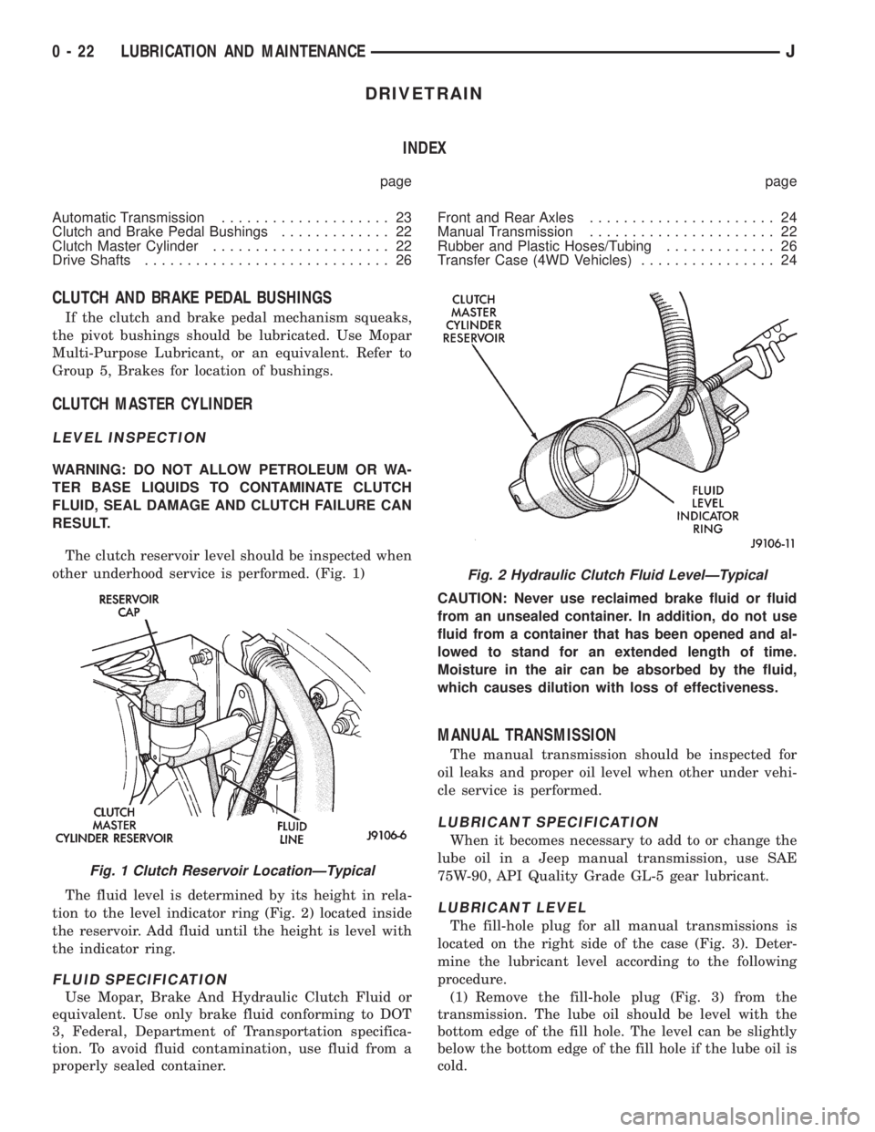
other underhood service is performed. (Fig. 1)
The fluid level is determined by its height in rela-
tion to the level indicator ring (Fig. 2) located inside
the reservoir. Add fluid until the height is level with
the indicator ring.
FLUID SPECIFICATION
Use Mopar, Brake And Hydraulic Clutch Fluid or
equivalent. Use only brake fluid conforming to DOT
3, Federal, Department of Transportation specifica-
tion. To avoid fluid contamination, use fluid from a
properly sealed container.CAUTION: Never use reclaimed brake fluid or fluid
from an unsealed container. In addition, do not use
fluid from a container that has been opened and al-
lowed to stand for an extended length of time.
Moisture in the air can be absorbed by the fluid,
which causes dilution with loss of effectiveness.
MANUAL TRANSMISSION
The manual transmission should be inspected for
oil leaks and proper oil level when other under vehi-
cle service is performed.
LUBRICANT SPECIFICATION
When it becomes necessary to add to or change the
lube oil in a Jeep manual transmission, use SAE
75W-90, API Quality Grade GL-5 gear lubricant.
LUBRICANT LEVEL
The fill-hole plug for all manual transmissions is
located on the right side of the case (Fig. 3). Deter-
mine the lubricant level according to the following
procedure.
(1) Remove the fill-hole plug (Fig. 3) from the
transmission. The lube oil should be level with the
bottom edge of the fill hole. The level can be slightly
below the bottom edge of the fill hole if the lube oil is
cold.
Fig. 1 Clutch Reservoir LocationÐTypical
Fig. 2 Hydraulic Clutch Fluid LevelÐTypical
0 - 22 LUBRICATION AND MAINTENANCEJ
Page 36 of 2198
FRONT SUSPENSION AND AXLE
CONTENTS
page page
AXLE NOISE/VIBRATION DIAGNOSIS........ 18
AXLE SPECIFICATIONS................... 49
FRONT WHEEL ALIGNMENT................ 5
GENERAL INFORMATION.................. 1MODEL 30 AXLE AND TUBE AXLE (2WD).... 22
TORQUE SPECIFICATIONS................ 49
XJ FRONT SUSPENSION.................. 11
YJ FRONT SUSPENSION.................. 15
GENERAL INFORMATION
FRONT SUSPENSION
XJ VEHICLES
The XJ front suspension is a link/coil design. This
suspension is use on Left Hand Drive (LHD) and
Right Hand Drive (RHD) vehicles. It is comprised of
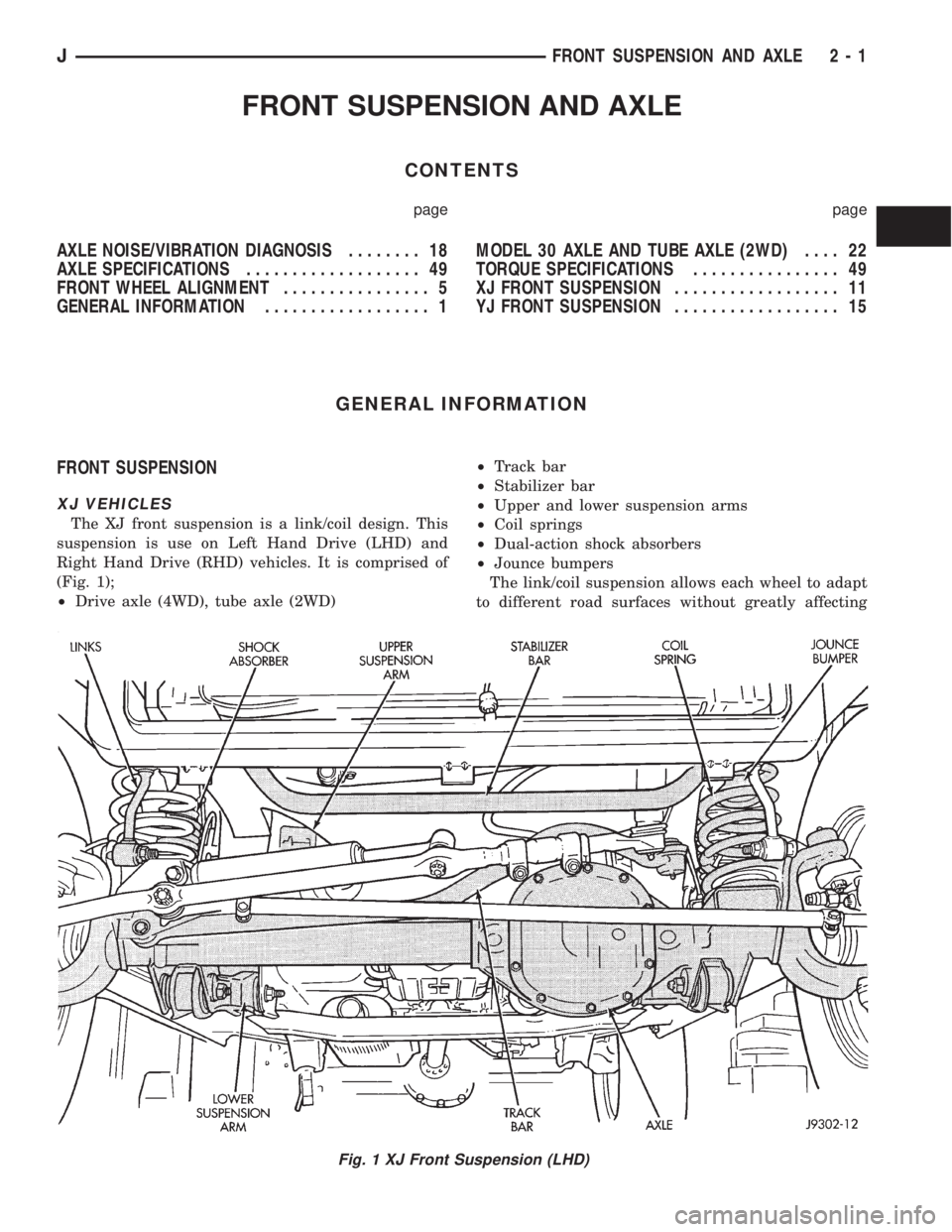
(Fig. 1);
²Drive axle (4WD), tube axle (2WD)²Track bar
²Stabilizer bar
²Upper and lower suspension arms
²Coil springs
²Dual-action shock absorbers
²Jounce bumpers
The link/coil suspension allows each wheel to adapt
to different road surfaces without greatly affecting
Fig. 1 XJ Front Suspension (LHD)
JFRONT SUSPENSION AND AXLE 2 - 1
Page 37 of 2198
the opposite wheel. Wheels are attached to a hub/
bearings which bolts to the knuckles. The hub/bear-
ing is not serviceable and is replaced as a unit.
Steering knuckles pivot on replaceable ball studs at-
tached to the axle tube yokes.
The upper and lower suspension arms are different
lengths, with bushings at both ends. They bolt the
axle assembly to the body. The lower arms uses
shims at the body mount to allow for adjustment of
caster and drive shaft pinion angle. The suspension
arm travel is limited through the use of jounce
bumpers in compression and shocks absorbers in re-
bound.
Suspension components which use rubber bushings
should be tightened at vehicle ride height. This will
prevent premature failure of the bushing and main-
tain ride comfort. Bushings must never be lubricated.
The coil springs control ride quality and maintain
proper ride height. The coil springs mount up in the
fender shield which is part of the unitized body
bracket. A rubber isolator is located between the top
of the spring and the frame. The bottom of the spring
seats on a axle pad and is retained with a clip.
The shock absorbers dampen jounce and rebound of
the vehicle over various road conditions. The top of
the shock absorbers are bolted to the body. The bot-
tom of the shocks are bolted to the axle spring
bracket.
The stabilizer bar is used to minimize vehicle body
roll during turns. The spring steel bar helps to con-
trol the vehicle body in relationship to the suspen-
sion. The bar extends across the front underside of
the chassis and connects to the body rails. Links are
connected from the bar to the axle brackets. Stabi-
lizer bar mounts are isolated by rubber bushings.
The track bar is used to minimize front axle side-
to-side movement. The bar is attached to a frame rail
bracket with a ball stud and isolated with a bushing
at the axle bracket.
TUBE AXLE (2WD VEHICLES)
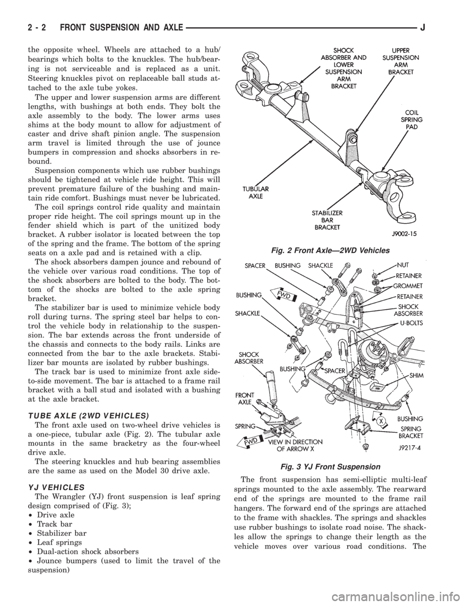
The front axle used on two-wheel drive vehicles is
a one-piece, tubular axle (Fig. 2). The tubular axle
mounts in the same bracketry as the four-wheel
drive axle.
The steering knuckles and hub bearing assemblies
are the same as used on the Model 30 drive axle.
YJ VEHICLES
The Wrangler (YJ) front suspension is leaf spring
design comprised of (Fig. 3);
²Drive axle
²Track bar
²Stabilizer bar
²Leaf springs
²Dual-action shock absorbers
²Jounce bumpers (used to limit the travel of the
suspension)The front suspension has semi-elliptic multi-leaf
springs mounted to the axle assembly. The rearward
end of the springs are mounted to the frame rail
hangers. The forward end of the springs are attached
to the frame with shackles. The springs and shackles
use rubber bushings to isolate road noise. The shack-
les allow the springs to change their length as the
vehicle moves over various road conditions. The
Fig. 2 Front AxleÐ2WD Vehicles
Fig. 3 YJ Front Suspension
2 - 2 FRONT SUSPENSION AND AXLEJ
Page 38 of 2198
spring and axle travel (jounce or rebound) is limited
through use of rubber bumpers mounted on the
frame.
Suspension components which use rubber bushings
should be tightened at vehicle ride height. This will
prevent premature failure of the bushing and main-
tain ride comfort. The bushings should never be lu-
bricated.
The shocks absorbers dampen jounce and rebound
of the vehicle over various road conditions. The top of
the shock absorbers bolt to the frame. The bottom of
the shocks bolt to the axle brackets.
The stabilizer bar is used to minimize vehicle front
sway during turns. The spring steel bar helps control
vehicle body in relationship to the suspension move-
ment. The bar extends across the front underside of
the chassis and connects to the frame rails. Links
connect the bar to the axle brackets. Stabilizer bar
mounts are isolated by rubber bushings.
The track bar is used to minimize front axle side-
to-side movement. The track bar is attached to a
frame rail bracket and axle bracket. The bar uses
bushings at both ends.
FRONT DRIVE AXLE
It is not necessary to remove the complete axle
from the vehicle for routine differential service. If the
differential housing or axle shaft tubes are damaged,
the complete axle assembly can be removed and ser-
viced.
For complete drive axle assembly removal and in-
stallation refer to Drive Axle Assembly Replacement
in this Group.
The removable cover provides for servicing without
removing axle from vehicle.
The integral type housing, hypoid gear design has
the centerline of the pinion set above the centerline
of the ring gear.
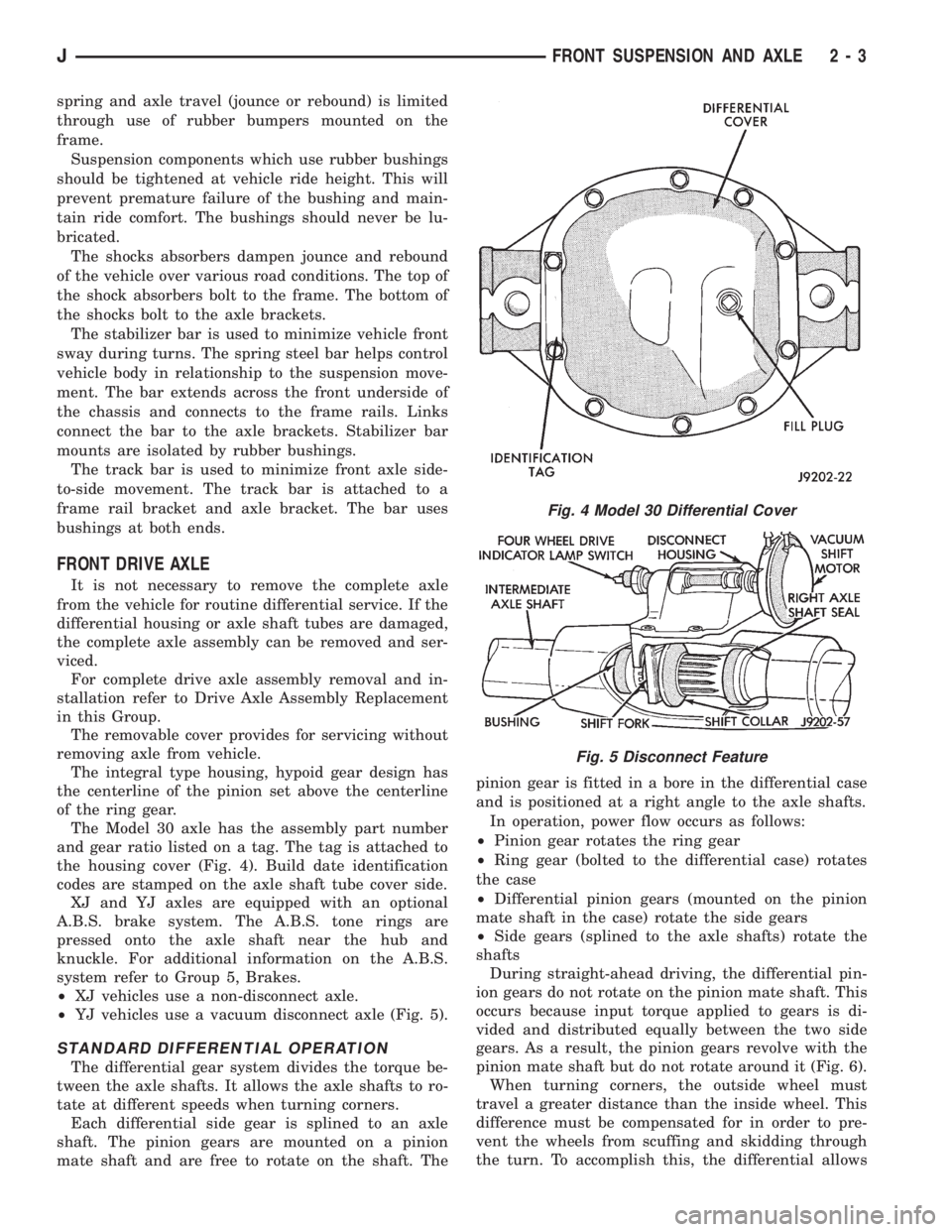
The Model 30 axle has the assembly part number
and gear ratio listed on a tag. The tag is attached to
the housing cover (Fig. 4). Build date identification
codes are stamped on the axle shaft tube cover side.
XJ and YJ axles are equipped with an optional
A.B.S. brake system. The A.B.S. tone rings are
pressed onto the axle shaft near the hub and
knuckle. For additional information on the A.B.S.
system refer to Group 5, Brakes.
²XJ vehicles use a non-disconnect axle.
²YJ vehicles use a vacuum disconnect axle (Fig. 5).
STANDARD DIFFERENTIAL OPERATION
The differential gear system divides the torque be-
tween the axle shafts. It allows the axle shafts to ro-
tate at different speeds when turning corners.
Each differential side gear is splined to an axle
shaft. The pinion gears are mounted on a pinion
mate shaft and are free to rotate on the shaft. Thepinion gear is fitted in a bore in the differential case
and is positioned at a right angle to the axle shafts.
In operation, power flow occurs as follows:
²Pinion gear rotates the ring gear
²Ring gear (bolted to the differential case) rotates
the case
²Differential pinion gears (mounted on the pinion
mate shaft in the case) rotate the side gears
²Side gears (splined to the axle shafts) rotate the
shafts
During straight-ahead driving, the differential pin-
ion gears do not rotate on the pinion mate shaft. This
occurs because input torque applied to gears is di-
vided and distributed equally between the two side
gears. As a result, the pinion gears revolve with the
pinion mate shaft but do not rotate around it (Fig. 6).
When turning corners, the outside wheel must
travel a greater distance than the inside wheel. This
difference must be compensated for in order to pre-
vent the wheels from scuffing and skidding through
the turn. To accomplish this, the differential allows
Fig. 4 Model 30 Differential Cover
Fig. 5 Disconnect Feature
JFRONT SUSPENSION AND AXLE 2 - 3
Page 46 of 2198
XJ FRONT SUSPENSION
INDEX
page page
Axle Bushing Replacement.................. 12
Coil Spring.............................. 14
Lower Suspension Arm..................... 13
Service Information........................ 11
Shock Absorber.......................... 13Spring and Shock Diagnosis................. 13
Stabilizer Bar............................ 11
Track Bar............................... 11
Upper Suspension Arm..................... 12
SERVICE INFORMATION
Periodic lubrication of the steering system and sus-
pension components is required. Refer to Group 0,
Lubrication And Maintenance for the service inter-
val.
CAUTION: Suspension components with rubber
bushings should be tightened with the vehicle at
normal height. It is important to have the springs
supporting the weight of the vehicle when the fas-
teners are torqued. If springs are not at their normal
ride position, vehicle ride comfort could be affected
and premature bushing wear may occur. Rubber
bushings must never be lubricated.
TRACK BAR
REMOVAL
(1) Raise and support the vehicle.
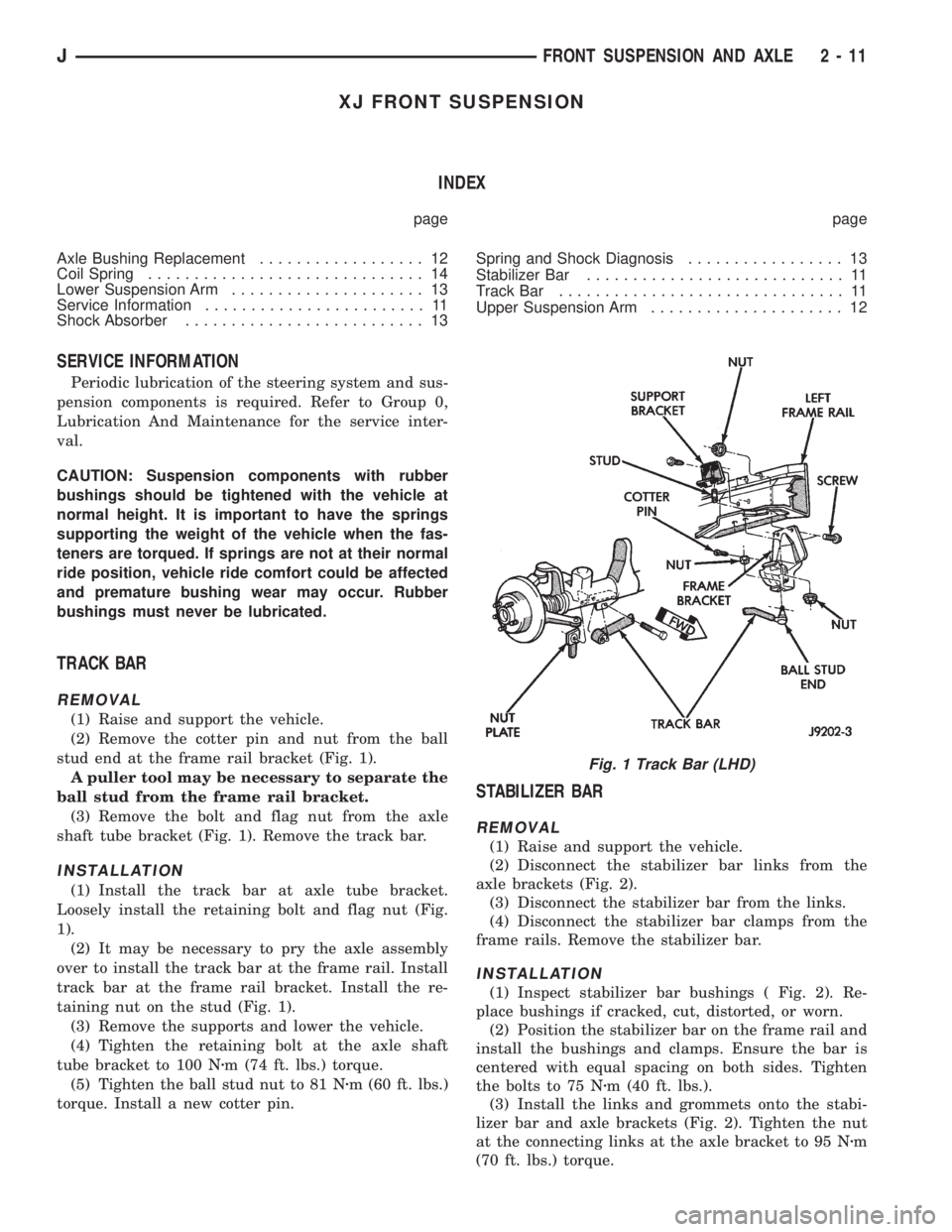
(2) Remove the cotter pin and nut from the ball
stud end at the frame rail bracket (Fig. 1).
A puller tool may be necessary to separate the
ball stud from the frame rail bracket.
(3) Remove the bolt and flag nut from the axle
shaft tube bracket (Fig. 1). Remove the track bar.
INSTALLATION
(1) Install the track bar at axle tube bracket.
Loosely install the retaining bolt and flag nut (Fig.
1).
(2) It may be necessary to pry the axle assembly
over to install the track bar at the frame rail. Install
track bar at the frame rail bracket. Install the re-
taining nut on the stud (Fig. 1).
(3) Remove the supports and lower the vehicle.
(4) Tighten the retaining bolt at the axle shaft
tube bracket to 100 Nzm (74 ft. lbs.) torque.
(5) Tighten the ball stud nut to 81 Nzm (60 ft. lbs.)
torque. Install a new cotter pin.
STABILIZER BAR
REMOVAL
(1) Raise and support the vehicle.
(2) Disconnect the stabilizer bar links from the
axle brackets (Fig. 2).
(3) Disconnect the stabilizer bar from the links.
(4) Disconnect the stabilizer bar clamps from the
frame rails. Remove the stabilizer bar.
INSTALLATION
(1) Inspect stabilizer bar bushings ( Fig. 2). Re-
place bushings if cracked, cut, distorted, or worn.
(2) Position the stabilizer bar on the frame rail and
install the bushings and clamps. Ensure the bar is
centered with equal spacing on both sides. Tighten
the bolts to 75 Nzm (40 ft. lbs.).
(3) Install the links and grommets onto the stabi-
lizer bar and axle brackets (Fig. 2). Tighten the nut
at the connecting links at the axle bracket to 95 Nzm
(70 ft. lbs.) torque.
Fig. 1 Track Bar (LHD)
JFRONT SUSPENSION AND AXLE 2 - 11
Page 48 of 2198
LOWER SUSPENSION ARM
REMOVAL
(1) Raise and support the vehicle.
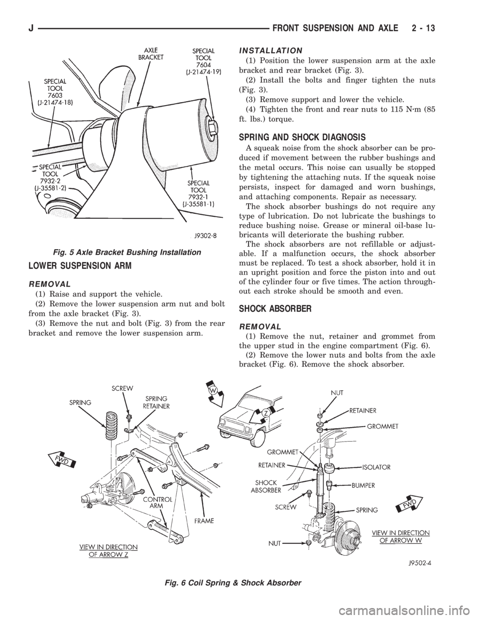
(2) Remove the lower suspension arm nut and bolt
from the axle bracket (Fig. 3).
(3) Remove the nut and bolt (Fig. 3) from the rear
bracket and remove the lower suspension arm.
INSTALLATION
(1) Position the lower suspension arm at the axle
bracket and rear bracket (Fig. 3).
(2) Install the bolts and finger tighten the nuts
(Fig. 3).
(3) Remove support and lower the vehicle.
(4) Tighten the front and rear nuts to 115 Nzm (85
ft. lbs.) torque.
SPRING AND SHOCK DIAGNOSIS
A squeak noise from the shock absorber can be pro-
duced if movement between the rubber bushings and
the metal occurs. This noise can usually be stopped
by tightening the attaching nuts. If the squeak noise
persists, inspect for damaged and worn bushings,
and attaching components. Repair as necessary.
The shock absorber bushings do not require any
type of lubrication. Do not lubricate the bushings to
reduce bushing noise. Grease or mineral oil-base lu-
bricants will deteriorate the bushing rubber.
The shock absorbers are not refillable or adjust-
able. If a malfunction occurs, the shock absorber
must be replaced. To test a shock absorber, hold it in
an upright position and force the piston into and out
of the cylinder four or five times. The action through-
out each stroke should be smooth and even.
SHOCK ABSORBER
REMOVAL
(1) Remove the nut, retainer and grommet from
the upper stud in the engine compartment (Fig. 6).
(2) Remove the lower nuts and bolts from the axle
bracket (Fig. 6). Remove the shock absorber.
Fig. 6 Coil Spring & Shock Absorber
Fig. 5 Axle Bracket Bushing Installation
JFRONT SUSPENSION AND AXLE 2 - 13
Page 49 of 2198
INSTALLATION
(1) Position the lower retainer and grommet on the
upper stud. Insert the shock absorber through the
shock tower hole.
(2) Install the lower bolts and nuts. Tighten nuts
to 23 Nzm (17 ft. lbs.) torque.
(3) Install the upper grommet and retainer on the
stud in the engine compartment. Install the nut and
tighten to 10 Nzm (8 ft. lbs.) torque.
COIL SPRING
REMOVAL
(1) Raise and support the vehicle. Position a hy-
draulic jack under the axle to support it.
(2) Remove the wheel if necessary.
(3) Mark and disconnect the front propeller shaft
from the axle.
(4) Disconnect the lower suspension arms from the
axle (Fig. 6).
(5) Disconnect the stabilizer bar link and shock ab-
sorber from the axle.
(6) Disconnect the track bar from the frame rail
bracket.(7) Disconnect the drag link from the pitman arm.
(8) Lower the axle until the spring is free from the
upper mount. Remove the coil spring clip (Fig. 6) and
remove the spring.
(9) Pull jounce bumper out of mount.
INSTALLATION
(1) Install jounce bumper into mount.
(2) Position the coil spring on the axle pad. Install
the spring clip and bolt (Fig. 6). Tighten bolt to 21
Nzm (16 ft. lbs.) torque.
(3) Raise the axle into position until the spring
seats in the upper mount.
(4) Connect the stabilizer bar links and shock ab-
sorbers to the axle bracket. Connect the track bar to
the frame rail bracket.
(5) Install the lower suspension arms to the axle.
DO NOT TIGHTEN AT THIS TIME.
(6) Install the front propeller shaft to the axle.
(7) Remove the supports and lower the vehicle.
(8) Tighten lower suspension arms nuts to 115 Nzm
(85 ft. lbs.) torque.
2 - 14 FRONT SUSPENSION AND AXLEJ
Page 50 of 2198
YJ FRONT SUSPENSION
INDEX
page page
Leaf Spring.............................. 16
Leaf Spring Eye Bushing Replacement......... 17
Service Information........................ 15
Shock Absorber.......................... 16Spring and Shock Diagnosis................. 15
Stabilizer Bar............................ 15
Track Bar............................... 15
SERVICE INFORMATION
Periodic lubrication of the steering system and sus-
pension components is required. Refer to Group 0,
Lubrication And Maintenance for the service inter-
val.
CAUTION: Suspension components with rubber
bushings should be tightened with the vehicle at
normal height. It is important to have the springs
supporting the weight of the vehicle when the fas-
teners are torqued. If springs are not at their normal
ride position, vehicle ride comfort could be affected
and premature bushing wear may occur. Rubber
bushings must never be lubricated.
TRACK BAR
REMOVAL
(1) Raise and support the vehicle.
(2) Remove the retaining nuts and bolts (Fig. 1)
from the axle bracket and frame bracket. Remove
track bar.
INSTALLATION
(1) Position track bar at axle shaft tube bracket.
Loosely install the retaining bolt and nut (Fig. 1).
(2) Loosely install the retaining bolt and nut at the
frame bracket.
(3) Remove support and lower vehicle.
(4) Tighten the retaining nut at the axle shaft tube
bracket to 100 Nzm (74 ft. lbs.) torque.
(5) Tighten the retaining nut at the frame bracket
to 142 Nzm (105 ft. lbs.) torque.
STABILIZER BAR
REMOVAL
(1) Raise and support the vehicle.
(2) Remove the retaining nut from the connecting
link bolt (Fig. 2).
(3) Remove the retaining clamps from frame rails
(4) Remove the stabilizer bar.
INSTALLATION
(1) Inspect the stabilizer bar bushings (Fig. 2). Re-
place the bushings if cracked, cut, distorted, or worn.(2) Position the stabilizer bar on the frame. Install
the retaining brackets and fasteners. Tighten bolts to
41 Nzm (30 ft. lbs.) torque.
(3) Install the link upper bolts and nuts. Tighten
the nuts to 61 Nzm (45 ft. lbs.) torque.
(4) Tighten the link spring bracket nuts to 61 Nzm
(45 ft. lbs.) torque.
(5) Lower the vehicle.
SPRING AND SHOCK DIAGNOSIS
A squeak noise from the shock absorber or springs
can be produced if movement between the rubber
bushings and the metal occurs. This noise can usu-
ally be stopped by tightening the attaching nuts. If
the squeak noise persists, inspect for damaged and
worn bushings, and attaching components. Repair as
necessary if any of these conditions exist.
Fig. 1 Track Bar
JFRONT SUSPENSION AND AXLE 2 - 15