JEEP CHEROKEE 1995 Service Repair Manual
Manufacturer: JEEP, Model Year: 1995, Model line: CHEROKEE, Model: JEEP CHEROKEE 1995Pages: 2198, PDF Size: 82.83 MB
Page 401 of 2198
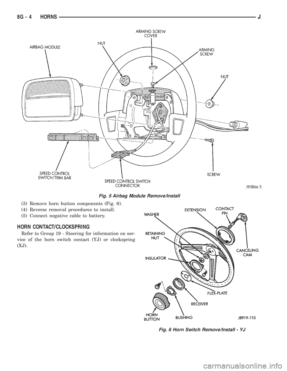
(3) Remove horn button components (Fig. 6).
(4) Reverse removal procedures to install.
(5) Connect negative cable to battery.
HORN CONTACT/CLOCKSPRING
Refer to Group 19 - Steering for information on ser-
vice of the horn switch contact (YJ) or clockspring
(XJ).
Fig. 5 Airbag Module Remove/Install
Fig. 6 Horn Switch Remove/Install - YJ
8G - 4 HORNSJ
Page 402 of 2198

SPECIFICATIONS
JHORNS 8G - 5
Page 403 of 2198

Page 404 of 2198
VEHICLE SPEED CONTROL SYSTEM
CONTENTS
page page
DIAGNOSIS............................. 2
GENERAL INFORMATION.................. 1SERVICE PROCEDURES................... 9
GENERAL INFORMATION
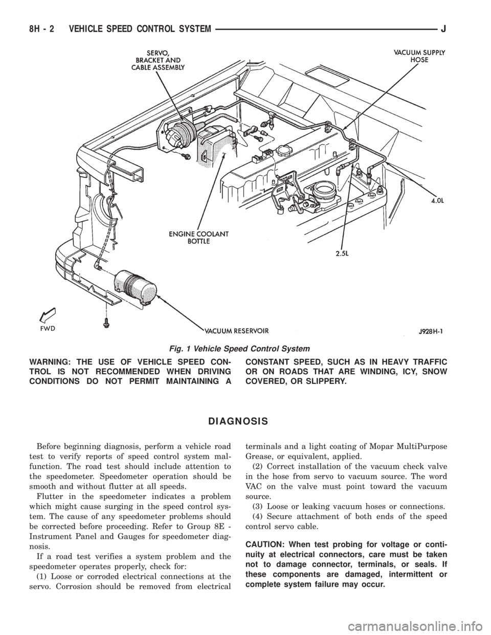
The vehicle speed control system (Fig. 1) is an
available option on all XJ (Cherokee) models. The
system is electronically controlled and vacuum oper-
ated. Following are general descriptions of the major
components in the vehicle speed control system. Re-
fer to Group 8W - Wiring Diagrams for complete cir-
cuit descriptions and diagrams.
SPEED CONTROL SERVO
The speed control servo is mounted to a bracket on
the right side inner fender shield in the engine com-
partment. The servo unit consists of a solenoid valve
body, a vacuum servo and the mounting bracket. The
PCM controls the solenoid valve body. The solenoid
valve body controls the application and release of
vacuum to the diaphragm of the vacuum servo. The
servo unit cannot be repaired and is serviced only as
a complete assembly.
SPEED CONTROL SWITCH
The speed control switch module is mounted to the
center of the steering wheel below the driver's airbag
module. The PCM monitors the state of the speed
control switches. The individual switches are labeled:
OFF/ON, RESUME/ACCEL, SET/COAST. Refer to
the owner's manual for more information on speed
control switch functions and setting procedures. The
individual switches cannot be repaired. If one switch
fails, the entire switch module must be replaced.
STOP LAMP SWITCH
Vehicles with the speed control option use a dual
function stop lamp switch. The switch is mounted in
the same location as the conventional stop lamp
switch, on the brake pedal mounting bracket under
the instrument panel. The PCM monitors the state of
the dual function stop lamp switch. Refer to Group 5
- Brakes for more information on stop lamp switch
service and adjustment procedures.
SERVO CABLE
The speed control servo cable is connected betweenthe speed control vacuum servo diaphragm and the
throttle control linkage. This cable causes the throt-
tle control linkage to open or close the throttle valve
in response to movement of the vacuum servo dia-
phragm.
POWERTRAIN CONTROL MODULE
The speed control electronic control circuitry is in-
tegrated into the Powertrain Control Module (PCM).
The PCM is located in the engine compartment on
the left side inner fender shield. The PCM speed con-
trol functions are monitored by the On-Board Diag-
nostics (OBD). All OBD-sensed systems are
monitored by the PCM. Each monitored circuit is as-
signed a Diagnostic Trouble Code (DTC). The PCM
will store a DTC in electronic memory for any failure
it detects. See Using On-Board Diagnostic System in
this group for more information. The PCM cannot be
repaired and must be replaced if faulty.
VACUUM RESERVOIR
The vacuum reservoir is mounted behind the left
end of the front bumper bar. The reservoir contains a
one-way check valve to trap engine vacuum in the
reservoir. When engine vacuum drops, as in climbing
a grade while driving, the reservoir supplies the vac-
uum needed to maintain proper speed control opera-
tion. The vacuum reservoir cannot be repaired and
must be replaced if faulty.
VEHICLE SPEED SENSOR
The Vehicle Speed Sensor (VSS) is a pulse genera-
tor mounted to an adapter near the transmission
(two-wheel drive) or transfer case (four-wheel drive)
output shaft. The sensor is driven through the
adapter by a speedometer pinion gear. The VSS pulse
signal to the speedometer/odometer is monitored by
the PCM speed control circuitry to determine vehicle
speed and to maintain speed control set speed. Refer
to the appropriate Powertrain Diagnostic Procedures
manual for testing of this component. Refer to Group
14 - Fuel System for service of this component.
JVEHICLE SPEED CONTROL SYSTEM 8H - 1
Page 405 of 2198
WARNING: THE USE OF VEHICLE SPEED CON-
TROL IS NOT RECOMMENDED WHEN DRIVING
CONDITIONS DO NOT PERMIT MAINTAINING ACONSTANT SPEED, SUCH AS IN HEAVY TRAFFIC
OR ON ROADS THAT ARE WINDING, ICY, SNOW
COVERED, OR SLIPPERY.
DIAGNOSIS
Before beginning diagnosis, perform a vehicle road
test to verify reports of speed control system mal-
function. The road test should include attention to
the speedometer. Speedometer operation should be
smooth and without flutter at all speeds.
Flutter in the speedometer indicates a problem
which might cause surging in the speed control sys-
tem. The cause of any speedometer problems should
be corrected before proceeding. Refer to Group 8E -
Instrument Panel and Gauges for speedometer diag-
nosis.
If a road test verifies a system problem and the
speedometer operates properly, check for:
(1) Loose or corroded electrical connections at the
servo. Corrosion should be removed from electricalterminals and a light coating of Mopar MultiPurpose
Grease, or equivalent, applied.
(2) Correct installation of the vacuum check valve
in the hose from servo to vacuum source. The word
VAC on the valve must point toward the vacuum
source.
(3) Loose or leaking vacuum hoses or connections.
(4) Secure attachment of both ends of the speed
control servo cable.
CAUTION: When test probing for voltage or conti-
nuity at electrical connectors, care must be taken
not to damage connector, terminals, or seals. If
these components are damaged, intermittent or
complete system failure may occur.
Fig. 1 Vehicle Speed Control System
8H - 2 VEHICLE SPEED CONTROL SYSTEMJ
Page 406 of 2198
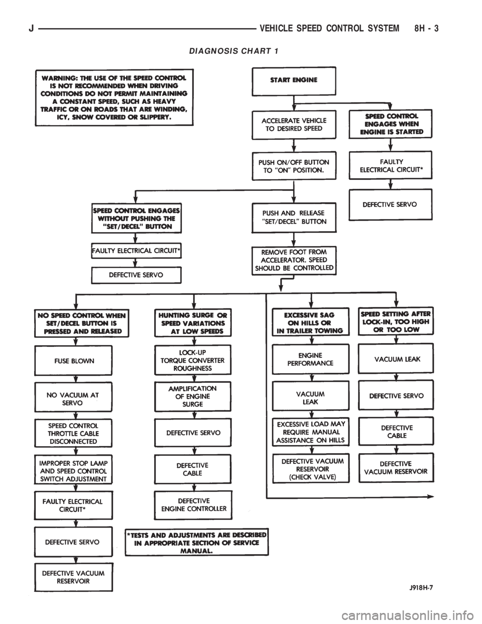
DIAGNOSIS CHART 1
JVEHICLE SPEED CONTROL SYSTEM 8H - 3
Page 407 of 2198
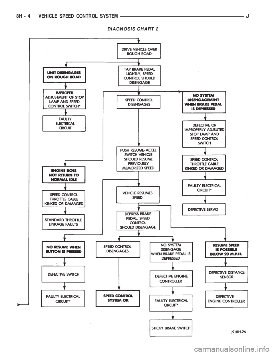
DIAGNOSIS CHART 2
8H - 4 VEHICLE SPEED CONTROL SYSTEMJ
Page 408 of 2198
USING ON-BOARD DIAGNOSTIC SYSTEM
The Powertrain Control Module (PCM) monitors
critical input and output circuits of the speed control
system, making sure they are operational. A Diagnos-
tic Trouble Code (DTC) is assigned to each input and
output circuit monitored by the OBD system. Some
circuits are checked continuously and some are
checked only under certain conditions.
If the OBD system senses that a monitored circuit
is bad, it will put a DTC into electronic memory. The
DTC will stay in electronic memory as long as the
circuit continues to be bad. The PCM is programmed
to clear the memory after 50 engine starts, if the
problem does not occur again.
DIAGNOSTIC TROUBLE CODES
Diagnostic Trouble Codes (DTC) are two-digit num-
bers flashed on the malfunction indicator (Check En-
gine) lamp that identify which circuit is bad. A DTC
description can also be read using the DRB scan tool.
Refer to Group 14 - Fuel Systems for more informa-
tion.
A DTC does not identify which component in a cir-
cuit is bad. Thus, a DTC should be treated as a
symptom, not as the cause for the problem. In some
cases, because of the design of the diagnostic test
procedure, a DTC can be the reason for another DTC
to be set. Therefore, it is important that the test pro-
cedures be followed in sequence, to understand what
caused a DTC to be set.
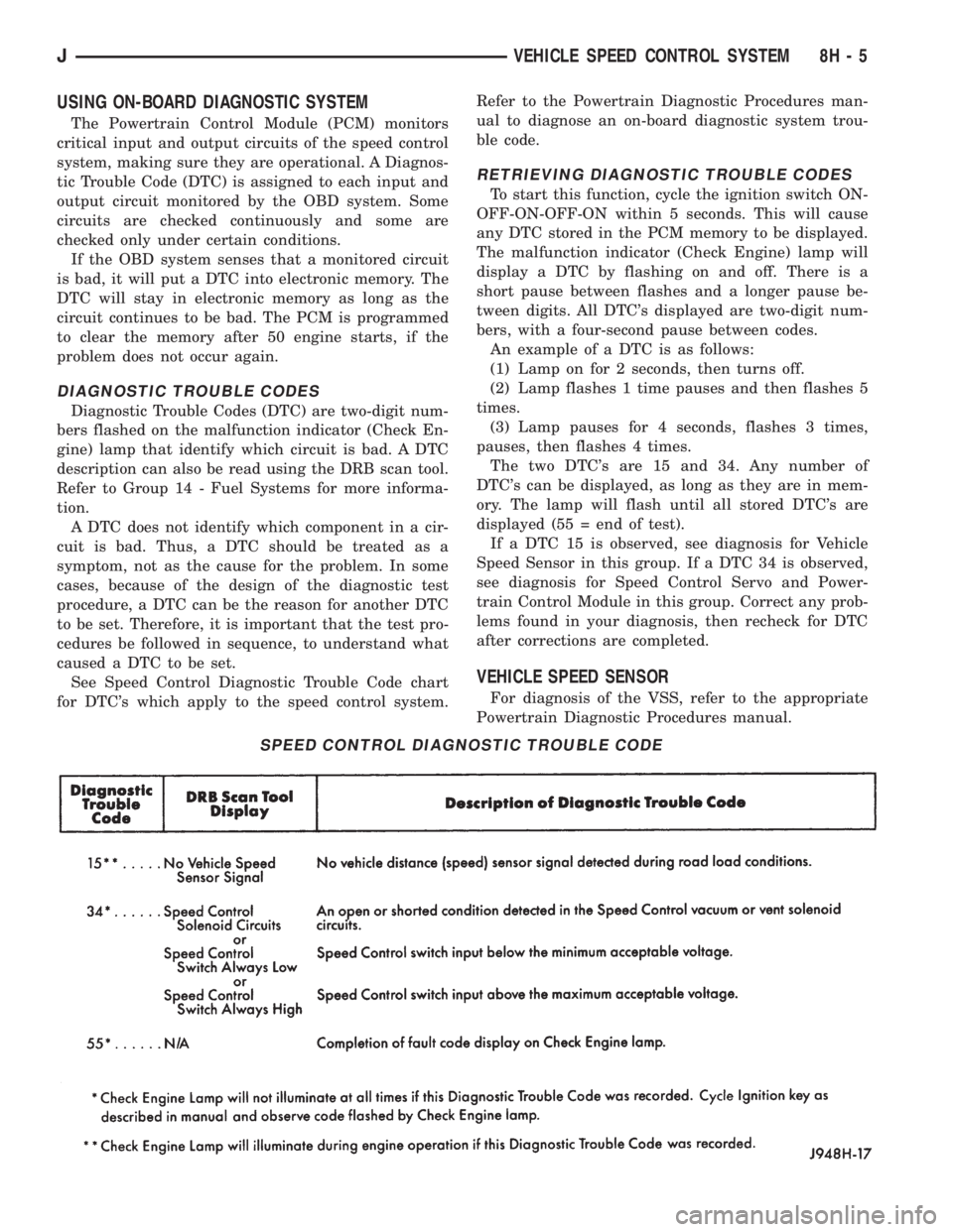
See Speed Control Diagnostic Trouble Code chart
for DTC's which apply to the speed control system.Refer to the Powertrain Diagnostic Procedures man-
ual to diagnose an on-board diagnostic system trou-
ble code.
RETRIEVING DIAGNOSTIC TROUBLE CODES
To start this function, cycle the ignition switch ON-
OFF-ON-OFF-ON within 5 seconds. This will cause
any DTC stored in the PCM memory to be displayed.
The malfunction indicator (Check Engine) lamp will
display a DTC by flashing on and off. There is a
short pause between flashes and a longer pause be-
tween digits. All DTC's displayed are two-digit num-
bers, with a four-second pause between codes.
An example of a DTC is as follows:
(1) Lamp on for 2 seconds, then turns off.
(2) Lamp flashes 1 time pauses and then flashes 5
times.
(3) Lamp pauses for 4 seconds, flashes 3 times,
pauses, then flashes 4 times.
The two DTC's are 15 and 34. Any number of
DTC's can be displayed, as long as they are in mem-
ory. The lamp will flash until all stored DTC's are
displayed (55 = end of test).
If a DTC 15 is observed, see diagnosis for Vehicle
Speed Sensor in this group. If a DTC 34 is observed,
see diagnosis for Speed Control Servo and Power-
train Control Module in this group. Correct any prob-
lems found in your diagnosis, then recheck for DTC
after corrections are completed.
VEHICLE SPEED SENSOR
For diagnosis of the VSS, refer to the appropriate
Powertrain Diagnostic Procedures manual.
SPEED CONTROL DIAGNOSTIC TROUBLE CODE
JVEHICLE SPEED CONTROL SYSTEM 8H - 5
Page 409 of 2198
SPEED CONTROL SWITCH
WARNING: ON VEHICLES EQUIPPED WITH AN AIR-
BAG, REFER TO GROUP 8M - RESTRAINT SYS-
TEMS BEFORE ATTEMPTING STEERING WHEEL
COMPONENT DIAGNOSIS OR SERVICE. FAILURE
TO TAKE PROPER PRECAUTIONS COULD RESULT
IN ACCIDENTAL AIRBAG DEPLOYMENT AND POS-
SIBLE PERSONAL INJURY.
(1) Disconnect battery negative cable. Remove
speed control switch from steering wheel.
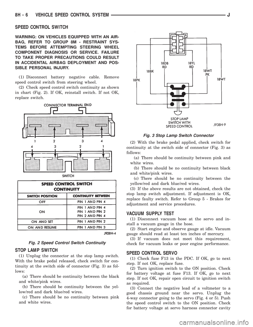
(2) Check speed control switch continuity as shown
in chart (Fig. 2). If OK, reinstall switch. If not OK,
replace switch.
STOP LAMP SWITCH
(1) Unplug the connector at the stop lamp switch.
With the brake pedal released, check switch for con-
tinuity at the switch side of connector (Fig. 3) as fol-
lows:
(a) There should be continuity between the black
and white/pink wires.
(b) There should be continuity between the yel-
low/red and dark blue/red wires.
(c) There should be no continuity between pink
and white wires.(2) With the brake pedal applied, check switch for
continuity at the switch side of connector (Fig. 3) as
follows:
(a) There should be continuity between pink and
white wires.
(b) There should be no continuity between black
and white/pink wires.
(c) There should be no continuity between the
yellow/red and dark blue/red wires.
(3) If the above results are not obtained, check the
stop lamp switch adjustment. If adjustment is OK,
replace faulty switch. Refer to Group 5 - Brakes for
adjustment and service procedures.
VACUUM SUPPLY TEST
(1) Disconnect vacuum hose at the servo and in-
stall a vacuum gauge in the hose.
(2) Start engine and observe gauge at idle. Vacuum
gauge should read at least ten inches of mercury.
(3) If vacuum does not meet this requirement,
check for vacuum leaks or poor engine performance.
SPEED CONTROL SERVO
(1) Check fuse F13 in the PDC. If OK, go to next
step. If not OK, replace fuse.
(2) Turn ignition switch to the ON position. Check
for battery voltage at fuse F13. If OK, go to next
step. If not OK, repair open circuit to ignition switch
as required.
(3) Connect the negative lead of a voltmeter to a
good chassis ground near the servo. Unplug the
4-way connector going to the servo (Fig. 4 or 5). Push
the speed control switch to the ON position. Check
for battery voltage at servo harness connector cavity
Fig. 2 Speed Control Switch Continuity
Fig. 3 Stop Lamp Switch Connector
8H - 6 VEHICLE SPEED CONTROL SYSTEMJ
Page 410 of 2198
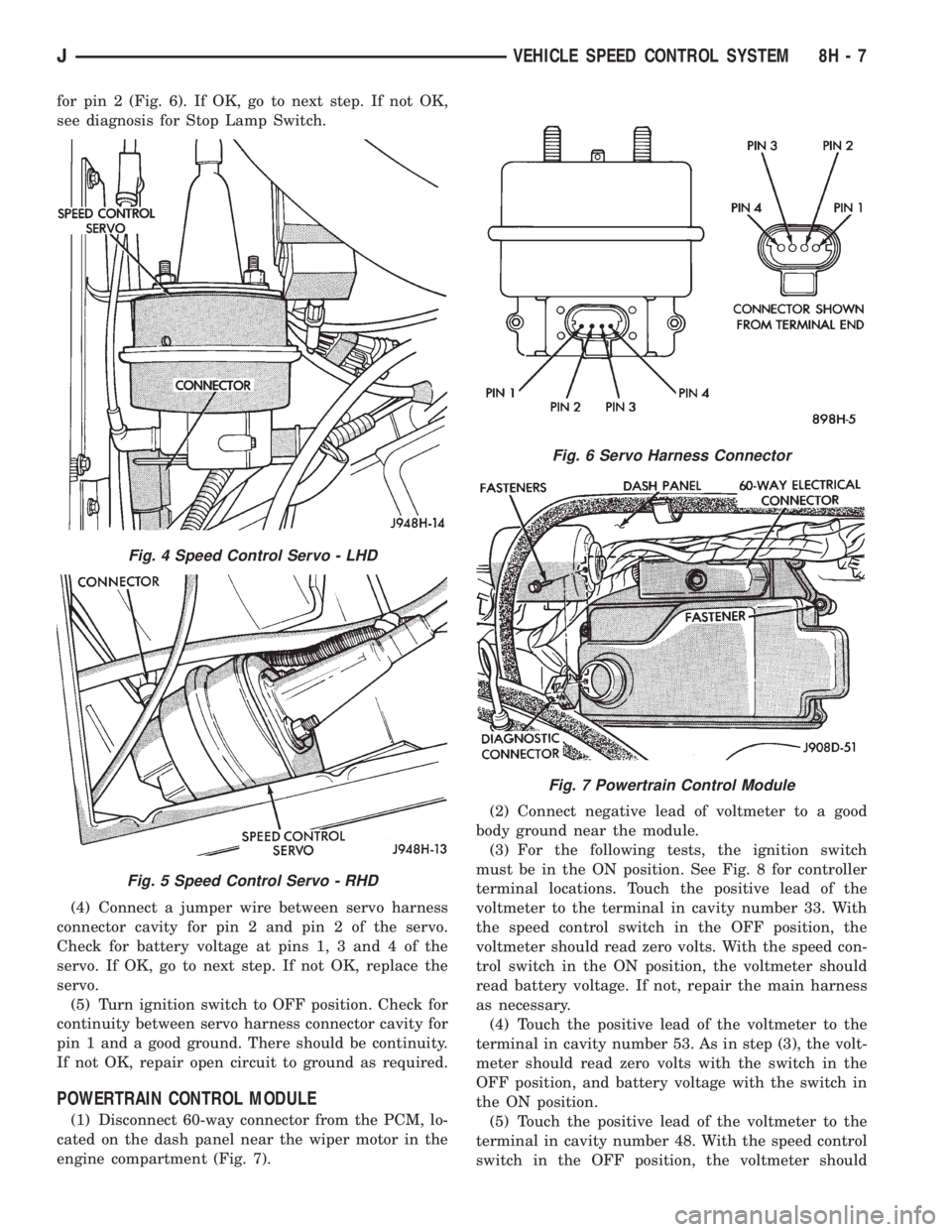
for pin 2 (Fig. 6). If OK, go to next step. If not OK,
see diagnosis for Stop Lamp Switch.
(4) Connect a jumper wire between servo harness
connector cavity for pin 2 and pin 2 of the servo.
Check for battery voltage at pins 1, 3 and 4 of the
servo. If OK, go to next step. If not OK, replace the
servo.
(5) Turn ignition switch to OFF position. Check for
continuity between servo harness connector cavity for
pin 1 and a good ground. There should be continuity.
If not OK, repair open circuit to ground as required.
POWERTRAIN CONTROL MODULE
(1) Disconnect 60-way connector from the PCM, lo-
cated on the dash panel near the wiper motor in the
engine compartment (Fig. 7).(2) Connect negative lead of voltmeter to a good
body ground near the module.
(3) For the following tests, the ignition switch
must be in the ON position. See Fig. 8 for controller
terminal locations. Touch the positive lead of the
voltmeter to the terminal in cavity number 33. With
the speed control switch in the OFF position, the
voltmeter should read zero volts. With the speed con-
trol switch in the ON position, the voltmeter should
read battery voltage. If not, repair the main harness
as necessary.
(4) Touch the positive lead of the voltmeter to the
terminal in cavity number 53. As in step (3), the volt-
meter should read zero volts with the switch in the
OFF position, and battery voltage with the switch in
the ON position.
(5) Touch the positive lead of the voltmeter to the
terminal in cavity number 48. With the speed control
switch in the OFF position, the voltmeter should
Fig. 4 Speed Control Servo - LHD
Fig. 5 Speed Control Servo - RHD
Fig. 6 Servo Harness Connector
Fig. 7 Powertrain Control Module
JVEHICLE SPEED CONTROL SYSTEM 8H - 7