brake sensor JEEP CHEROKEE 1995 Service Service Manual
[x] Cancel search | Manufacturer: JEEP, Model Year: 1995, Model line: CHEROKEE, Model: JEEP CHEROKEE 1995Pages: 2198, PDF Size: 82.83 MB
Page 1235 of 2198
provides a ground for the ignition coil. The coil dis-
charges when the PCM supplies a ground. By switch-
ing the ground path on and off, the PCM regulates
ignition timing.
The sensors and switches that provide inputs to
the powertrain control module (PCM) comprise the
Engine Control System. It is also comprised of the
PCM Outputs (engine control devices that the are op-
erated by the PCM).
SYSTEM DIAGNOSIS
The powertrain control module (PCM) tests many
of its own input and output circuits. If a Diagnostic
Trouble Code (DTC) is found in a major system, this
information is stored in the PCM memory. Refer to
On-Board Diagnostics in the MFI SystemÐGeneral
Diagnosis section of this group for DTC information.
POWERTRAIN CONTROL MODULE (PCM)
The PCM operates the fuel system. The PCM was
formerly referred to as the SBEC or engine control-
ler. The PCM is a pre-programmed, dual microproces-
sor digital computer. It regulates ignition timing, air-
fuel ratio, emission control devices, charging system,
speed control, air conditioning compressor clutch en-
gagement and idle speed. The PCM can adapt its
programming to meet changing operating conditions.
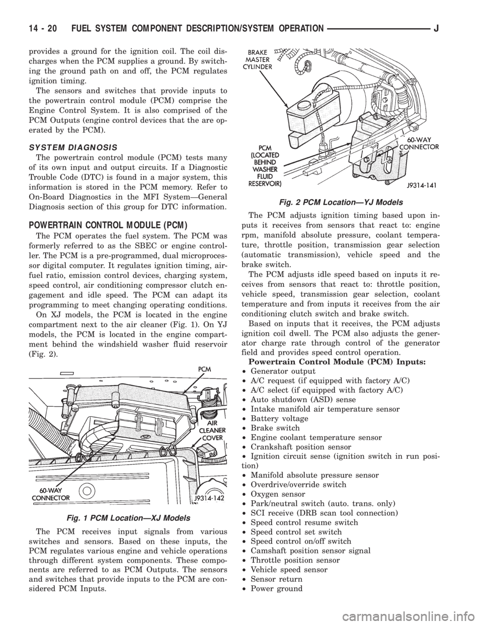
On XJ models, the PCM is located in the engine
compartment next to the air cleaner (Fig. 1). On YJ
models, the PCM is located in the engine compart-
ment behind the windshield washer fluid reservoir
(Fig. 2).
The PCM receives input signals from various
switches and sensors. Based on these inputs, the
PCM regulates various engine and vehicle operations
through different system components. These compo-
nents are referred to as PCM Outputs. The sensors
and switches that provide inputs to the PCM are con-
sidered PCM Inputs.The PCM adjusts ignition timing based upon in-
puts it receives from sensors that react to: engine
rpm, manifold absolute pressure, coolant tempera-
ture, throttle position, transmission gear selection
(automatic transmission), vehicle speed and the
brake switch.
The PCM adjusts idle speed based on inputs it re-
ceives from sensors that react to: throttle position,
vehicle speed, transmission gear selection, coolant
temperature and from inputs it receives from the air
conditioning clutch switch and brake switch.
Based on inputs that it receives, the PCM adjusts
ignition coil dwell. The PCM also adjusts the gener-
ator charge rate through control of the generator
field and provides speed control operation.
Powertrain Control Module (PCM) Inputs:
²Generator output
²A/C request (if equipped with factory A/C)
²A/C select (if equipped with factory A/C)
²Auto shutdown (ASD) sense
²Intake manifold air temperature sensor
²Battery voltage
²Brake switch
²Engine coolant temperature sensor
²Crankshaft position sensor
²Ignition circuit sense (ignition switch in run posi-
tion)
²Manifold absolute pressure sensor
²Overdrive/override switch
²Oxygen sensor
²Park/neutral switch (auto. trans. only)
²SCI receive (DRB scan tool connection)
²Speed control resume switch
²Speed control set switch
²Speed control on/off switch
²Camshaft position sensor signal
²Throttle position sensor
²Vehicle speed sensor
²Sensor return
²Power ground
Fig. 1 PCM LocationÐXJ Models
Fig. 2 PCM LocationÐYJ Models
14 - 20 FUEL SYSTEM COMPONENT DESCRIPTION/SYSTEM OPERATIONJ
Page 1237 of 2198
energized). This is done to compensate for the re-
duced flow through injector caused by the lowered
voltage.
BRAKE SWITCHÐPCM INPUT
When the brake light switch is activated, the pow-
ertrain control module (PCM) receives an input indi-
cating that the brakes are being applied. After
receiving this input, the PCM maintains idle speed to
a scheduled rpm through control of the idle air con-
trol (IAC) motor. The brake switch input is also used
to operate the speed control system.
CAMSHAFT POSITION SENSORÐPCM INPUT
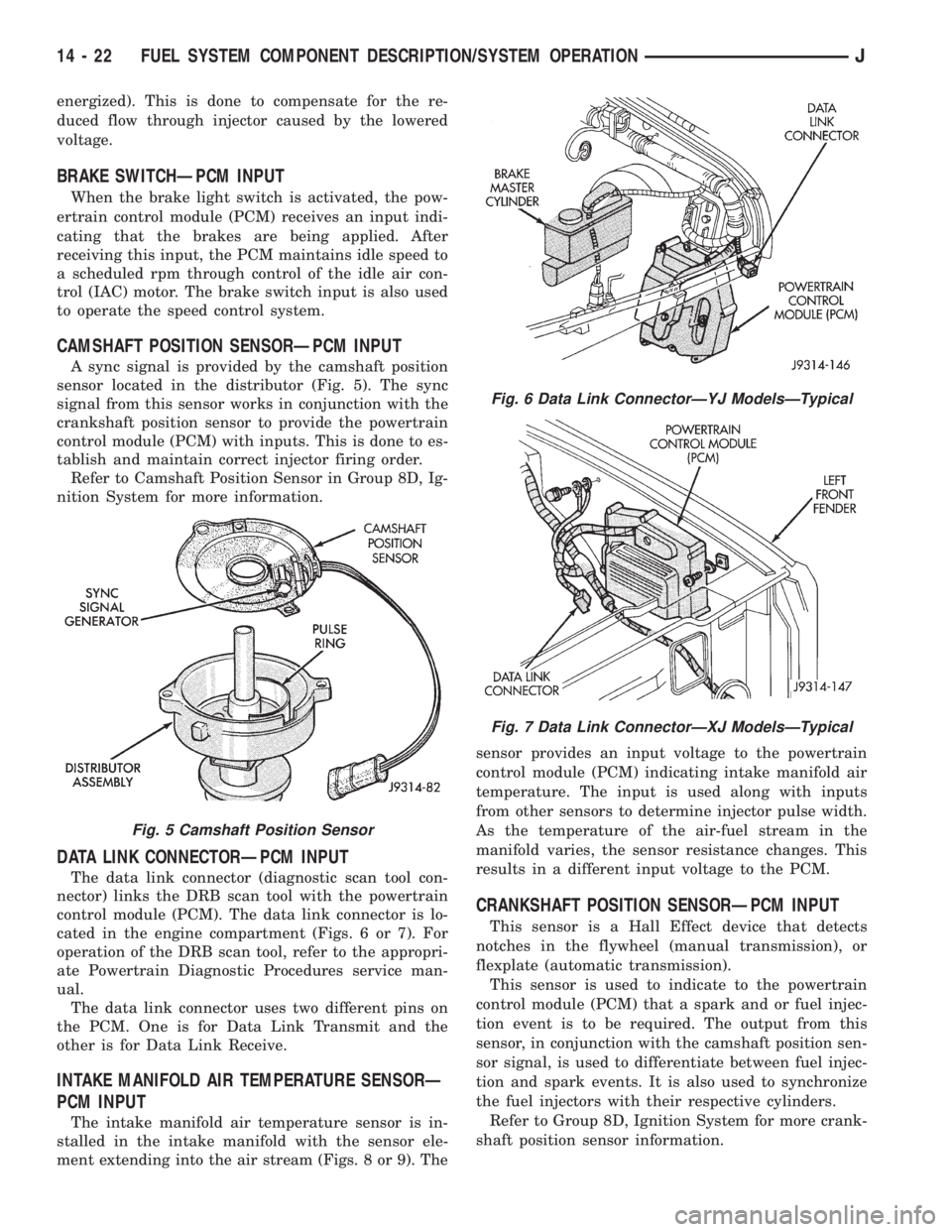
A sync signal is provided by the camshaft position
sensor located in the distributor (Fig. 5). The sync
signal from this sensor works in conjunction with the
crankshaft position sensor to provide the powertrain
control module (PCM) with inputs. This is done to es-
tablish and maintain correct injector firing order.
Refer to Camshaft Position Sensor in Group 8D, Ig-
nition System for more information.
DATA LINK CONNECTORÐPCM INPUT
The data link connector (diagnostic scan tool con-
nector) links the DRB scan tool with the powertrain
control module (PCM). The data link connector is lo-
cated in the engine compartment (Figs. 6 or 7). For
operation of the DRB scan tool, refer to the appropri-
ate Powertrain Diagnostic Procedures service man-
ual.
The data link connector uses two different pins on
the PCM. One is for Data Link Transmit and the
other is for Data Link Receive.
INTAKE MANIFOLD AIR TEMPERATURE SENSORÐ
PCM INPUT
The intake manifold air temperature sensor is in-
stalled in the intake manifold with the sensor ele-
ment extending into the air stream (Figs. 8 or 9). Thesensor provides an input voltage to the powertrain
control module (PCM) indicating intake manifold air
temperature. The input is used along with inputs
from other sensors to determine injector pulse width.
As the temperature of the air-fuel stream in the
manifold varies, the sensor resistance changes. This
results in a different input voltage to the PCM.
CRANKSHAFT POSITION SENSORÐPCM INPUT
This sensor is a Hall Effect device that detects
notches in the flywheel (manual transmission), or
flexplate (automatic transmission).
This sensor is used to indicate to the powertrain
control module (PCM) that a spark and or fuel injec-
tion event is to be required. The output from this
sensor, in conjunction with the camshaft position sen-
sor signal, is used to differentiate between fuel injec-
tion and spark events. It is also used to synchronize
the fuel injectors with their respective cylinders.
Refer to Group 8D, Ignition System for more crank-
shaft position sensor information.
Fig. 5 Camshaft Position Sensor
Fig. 6 Data Link ConnectorÐYJ ModelsÐTypical
Fig. 7 Data Link ConnectorÐXJ ModelsÐTypical
14 - 22 FUEL SYSTEM COMPONENT DESCRIPTION/SYSTEM OPERATIONJ
Page 1240 of 2198
SPEED CONTROLÐPCM INPUT
The speed control system provides three separate
inputs to the powertrain control module (PCM); On/
Off, Set and Resume. The On/Off input informs the
PCM that the speed control system has been acti-
vated. The Set input informs the PCM that a fixed
vehicle speed has been selected. The Resume input
indicates to the PCM that the previous fixed speed is
requested.
The speed control operating range is from 50 km/h
to 142 km/h (35 to 85 mph). Inputs that effect speed
control operation are:
²Brake switch position
²Park/neutral switch
²Vehicle speed sensor
²Throttle position sensor
Refer to Group 8H for further speed control infor-
mation.
SENSOR RETURNÐPCM INPUT
Sensor Return provides a low noise ground refer-
ence for all system sensors.
THROTTLE POSITION SENSOR (TPS)ÐPCM INPUT
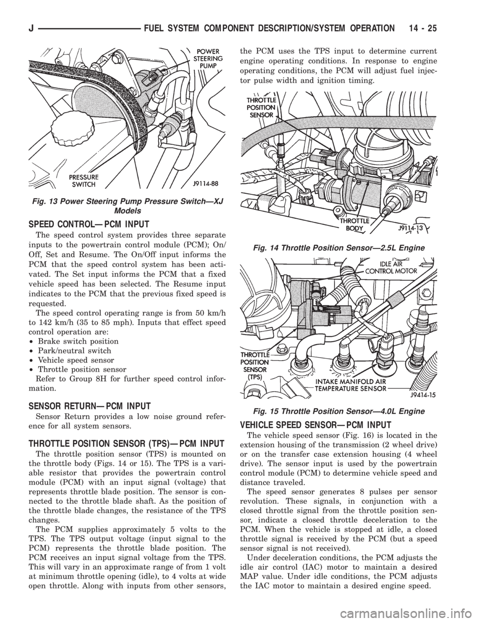
The throttle position sensor (TPS) is mounted on
the throttle body (Figs. 14 or 15). The TPS is a vari-
able resistor that provides the powertrain control
module (PCM) with an input signal (voltage) that
represents throttle blade position. The sensor is con-
nected to the throttle blade shaft. As the position of
the throttle blade changes, the resistance of the TPS
changes.
The PCM supplies approximately 5 volts to the
TPS. The TPS output voltage (input signal to the
PCM) represents the throttle blade position. The
PCM receives an input signal voltage from the TPS.
This will vary in an approximate range of from 1 volt
at minimum throttle opening (idle), to 4 volts at wide
open throttle. Along with inputs from other sensors,the PCM uses the TPS input to determine current
engine operating conditions. In response to engine
operating conditions, the PCM will adjust fuel injec-
tor pulse width and ignition timing.
VEHICLE SPEED SENSORÐPCM INPUT
The vehicle speed sensor (Fig. 16) is located in the
extension housing of the transmission (2 wheel drive)
or on the transfer case extension housing (4 wheel
drive). The sensor input is used by the powertrain
control module (PCM) to determine vehicle speed and
distance traveled.
The speed sensor generates 8 pulses per sensor
revolution. These signals, in conjunction with a
closed throttle signal from the throttle position sen-
sor, indicate a closed throttle deceleration to the
PCM. When the vehicle is stopped at idle, a closed
throttle signal is received by the PCM (but a speed
sensor signal is not received).
Under deceleration conditions, the PCM adjusts the
idle air control (IAC) motor to maintain a desired
MAP value. Under idle conditions, the PCM adjusts
the IAC motor to maintain a desired engine speed.
Fig. 13 Power Steering Pump Pressure SwitchÐXJ
Models
Fig. 14 Throttle Position SensorÐ2.5L Engine
Fig. 15 Throttle Position SensorÐ4.0L Engine
JFUEL SYSTEM COMPONENT DESCRIPTION/SYSTEM OPERATION 14 - 25
Page 1253 of 2198
verify that auxiliary radiator cooling fan wire connec-
tor is firmly connected to harness.
(15) Inspect the air cleaner inlet and air cleaner el-
ement for restrictions.(16) Inspect radiator grille area, radiator fins and
air conditioning condenser for restrictions.
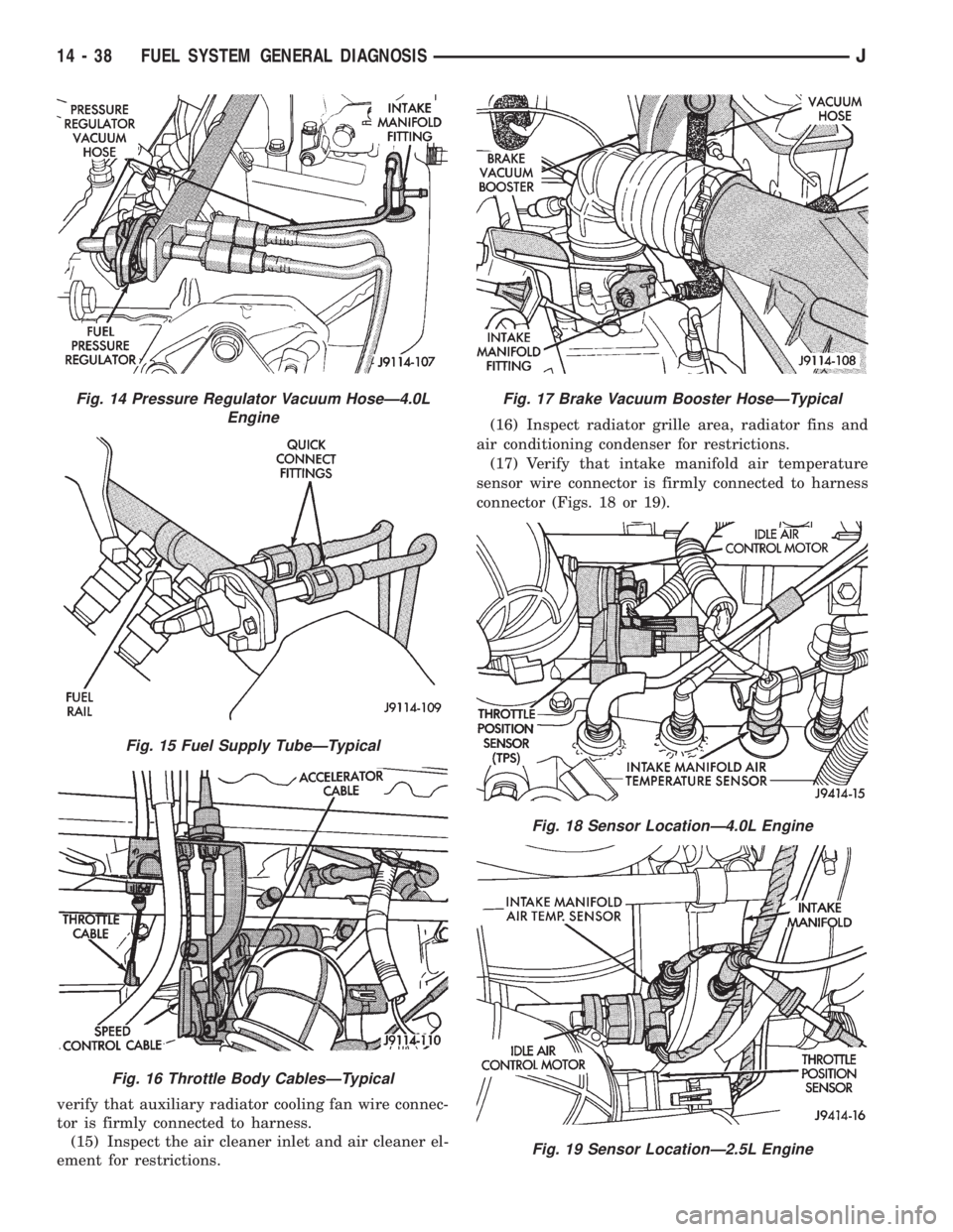
(17) Verify that intake manifold air temperature
sensor wire connector is firmly connected to harness
connector (Figs. 18 or 19).
Fig. 14 Pressure Regulator Vacuum HoseÐ4.0L
Engine
Fig. 15 Fuel Supply TubeÐTypical
Fig. 16 Throttle Body CablesÐTypical
Fig. 17 Brake Vacuum Booster HoseÐTypical
Fig. 18 Sensor LocationÐ4.0L Engine
Fig. 19 Sensor LocationÐ2.5L Engine
14 - 38 FUEL SYSTEM GENERAL DIAGNOSISJ
Page 1264 of 2198
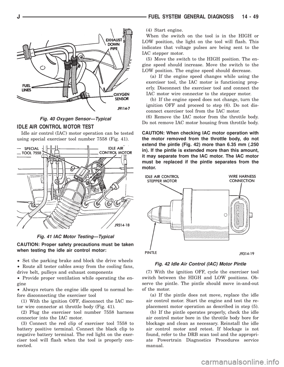
IDLE AIR CONTROL MOTOR TEST
Idle air control (IAC) motor operation can be tested
using special exerciser tool number 7558 (Fig. 41).
CAUTION: Proper safety precautions must be taken
when testing the idle air control motor:
²Set the parking brake and block the drive wheels
²Route all tester cables away from the cooling fans,
drive belt, pulleys and exhaust components
²Provide proper ventilation while operating the en-
gine
²Always return the engine idle speed to normal be-
fore disconnecting the exerciser tool
(1) With the ignition OFF, disconnect the IAC mo-
tor wire connector at throttle body (Fig. 41).
(2) Plug the exerciser tool number 7558 harness
connector into the IAC motor.
(3) Connect the red clip of exerciser tool 7558 to
battery positive terminal. Connect the black clip to
negative battery terminal. The red light on the exer-
ciser tool will flash when the tool is properly con-
nected.(4) Start engine.
When the switch on the tool is in the HIGH or
LOW position, the light on the tool will flash. This
indicates that voltage pulses are being sent to the
IAC stepper motor.
(5) Move the switch to the HIGH position. The en-
gine speed should increase. Move the switch to the
LOW position. The engine speed should decrease.
(a) If the engine speed changes while using the
exerciser tool, the IAC motor is functioning prop-
erly. Disconnect the exerciser tool and connect the
IAC motor wire connector to the stepper motor.
(b) If the engine speed does not change, turn the
ignition OFF and proceed to step (6). Do not dis-
connect exerciser tool from the IAC motor.
(6) Remove the IAC motor from the throttle body.
Do not remove IAC motor housing from throttle body.
CAUTION: When checking IAC motor operation with
the motor removed from the throttle body, do not
extend the pintle (Fig. 42) more than 6.35 mm (.250
in). If the pintle is extended more than this amount,
it may separate from the IAC motor. The IAC motor
must be replaced if the pintle separates from the
motor.
(7) With the ignition OFF, cycle the exerciser tool
switch between the HIGH and LOW positions. Ob-
serve the pintle. The pintle should move in-and-out
of the motor.
(a) If the pintle does not move, replace the idle
air control motor. Start the engine and test the re-
placement motor operation as described in step (5).
(b) If the pintle operates properly, check the idle
air control motor bore in the throttle body bore for
blockage and clean as necessary. Reinstall the idle
air control motor and retest. If blockage is not
found, refer to the DRB scan tool and the appropri-
ate Powertrain Diagnostics Procedures service
manual.
Fig. 40 Oxygen SensorÐTypical
Fig. 41 IAC Motor TestingÐTypical
Fig. 42 Idle Air Control (IAC) Motor Pintle
JFUEL SYSTEM GENERAL DIAGNOSIS 14 - 49
Page 1273 of 2198
MULTI-PORT FUEL INJECTION (MFI)ÐCOMPONENT REMOVAL/INSTALLATION
INDEX
page page
Accelerator Pedal and Throttle Cable........... 58
Air Cleaner Element....................... 59
Air Cleaner Housing....................... 58
Air Conditioning (A/C) Clutch Relay............ 58
Automatic Shutdown (ASD) Relay............. 59
Brake Switch............................ 59
Camshaft Position Sensor................... 60
Crankshaft Position Sensor.................. 60
Engine Coolant Temperature Sensor........... 60
Fuel Filter............................... 60
Fuel Injector............................. 60
Fuel Pressure Regulator.................... 61
Fuel Pump Module........................ 61
Fuel Pump Relay......................... 61
Fuel Rail Assembly........................ 62
Fuel System Pressure Release Procedure....... 62
Fuel Tank Pressure Relief/Rollover Valve........ 62Fuel Tanks.............................. 62
Fuel Tubes/Lines/Hoses and Clamps........... 62
Idle Air Control (IAC) Motor.................. 62
Ignition Coil............................. 62
Intake Manifold........................... 63
Intake Manifold Air Temperature Sensor......... 60
Manifold Absolute Pressure (Map) Sensor....... 63
Oxygen (O2S) Sensor...................... 63
Park Neutral Switch....................... 63
Power Steering Pressure SwitchÐ2.5L
Engine Only............................ 63
Powertrain Control Module (PCM)............. 64
Quick-Connect Fittings..................... 64
Throttle Body............................ 64
Throttle Position Sensor (TPS)............... 65
Torque Converter Clutch Relay............... 65
Vehicle Speed Sensor...................... 66
ACCELERATOR PEDAL AND THROTTLE CABLE
Refer to the Accelerator Pedal and Throttle Cable
section of this group for removal/installation proce-
dures.
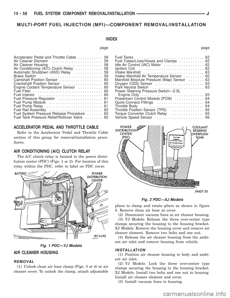
AIR CONDITIONING (A/C) CLUTCH RELAY
The A/C clutch relay is located in the power distri-
bution center (PDC) (Figs. 1 or 2). For location of this
relay within the PDC, refer to label on PDC cover.
AIR CLEANER HOUSING
REMOVAL
(1) Unlock clean air hose clamp (Figs. 3 or 4) at air
cleaner cover. To unlock the clamp, attach adjustablepliers to clamp and rotate pliers as shown in figure
5. Remove clean air hose at cover.
(2) Disconnect vacuum lines at air cleaner housing.
(3) YJ Models: Release the three over-center type
clamps securing the housing to the housing bracket.
XJ Models: Remove the housing cover and remove air
cleaner element. Remove two bolts and one nut.
(4) Release the air cleaner housing from the ambi-
ent air inlet and remove housing from vehicle.
INSTALLATION
(1) Position air cleaner housing to body and ambi-
ent air inlet.
(2) YJ Models: Lock the three over-center type
clamps securing the housing to the housing bracket.
XJ Models: Install two bolts and one nut to housing.
Install air cleaner element and cover.
(3) Install vacuum lines to housing.
Fig. 1 PDCÐYJ Models
Fig. 2 PDCÐXJ Models
14 - 58 FUEL SYSTEM COMPONENT REMOVAL/INSTALLATIONJ
Page 1482 of 2198
(7) Align valve body and seat it on case. Be sure
manual lever shaft and accumulator spring are prop-
erly seated.
(8) Hold valve body in position and install one or
two attaching bolts to hold valve body in place.
(9) Install remaining valve body bolts. Tighten all
bolts evenly in a diagonal pattern to 12 Nzm (105 in-
lbs) torque.
(10) Install new oil filter and tighten filter screws
to4Nzm (35 in. lbs.) torque.
(11) Connect converter solenoid wire to case con-
nector.
(12) Install manual and throttle levers on throttle
lever shaft. Tighten lever clamp screws and check for
free operation. Shaft and levers must operate freely
without any bind.
(13) Install oil pan and new gasket. Tighten pan
bolts to 17 Nzm (13 ft. lbs.) torque.
(14) Install seal on neutral switch, install switch in
case, and connect switch wires.
(15) Lower vehicle.
(16) Fill transmission with Mopar ATF Plus, Type
7176 fluid.
(17) Adjust gearshift linkage and throttle valve
(kickdown) cable if necessary.
GOVERNOR AND PARK GEAR SERVICE
GOVERNOR/PARK GEAR REMOVAL
(1) Raise vehicle.
(2) Mark both propeller shaft yokes for assembly
reference and disconnect propeller shafts at transfer
case.
(3) Disconnect speed sensor wires and remove
speedometer adapter and sensor.
(4) Position support stand under transmission con-
verter housing.
(5) Remove rear crossmember.
(6) Disconnect parking brake cable at equalizer
and disconnect exhaust components as necessary.
(7) Support transfer case with jack.
(8) Remove bolts attaching transfer case to trans-
mission adapter housing and remove transfer case.
(9) Remove bolts attaching adapter, or extension
housing to transmission and remove adapter/housing.
(10) Loosen but do not remove bolts that attach
governor body to park gear.
(11) Rotate transmission output shaft until gover-
nor weight assembly is accessible. Then remove
E-clip at this end of governor shaft.
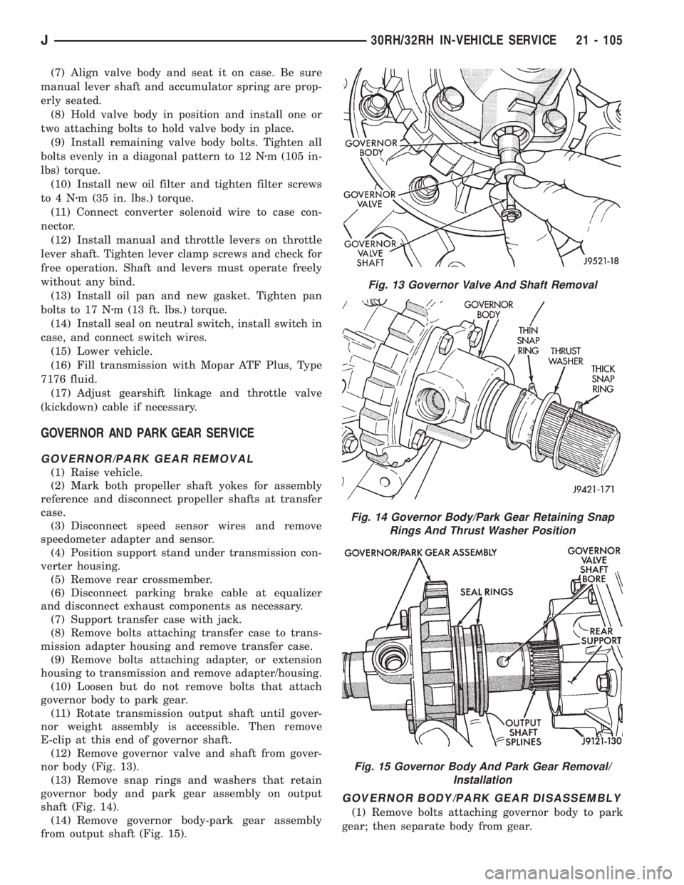
(12) Remove governor valve and shaft from gover-
nor body (Fig. 13).
(13) Remove snap rings and washers that retain
governor body and park gear assembly on output
shaft (Fig. 14).
(14) Remove governor body-park gear assembly
from output shaft (Fig. 15).
GOVERNOR BODY/PARK GEAR DISASSEMBLY
(1) Remove bolts attaching governor body to park
gear; then separate body from gear.
Fig. 13 Governor Valve And Shaft Removal
Fig. 14 Governor Body/Park Gear Retaining Snap
Rings And Thrust Washer Position
Fig. 15 Governor Body And Park Gear Removal/
Installation
J30RH/32RH IN-VEHICLE SERVICE 21 - 105
Page 1485 of 2198
bind if misalignment occurs. Remove and repo-
sition governor body if necessary.
(9) Verify that shaft bore in governor body and out-
put shaft are aligned.
(10) Verify that governor valve will be indexed
with spotface in output shaft. Reposition valve, shaft
and body if necessary.
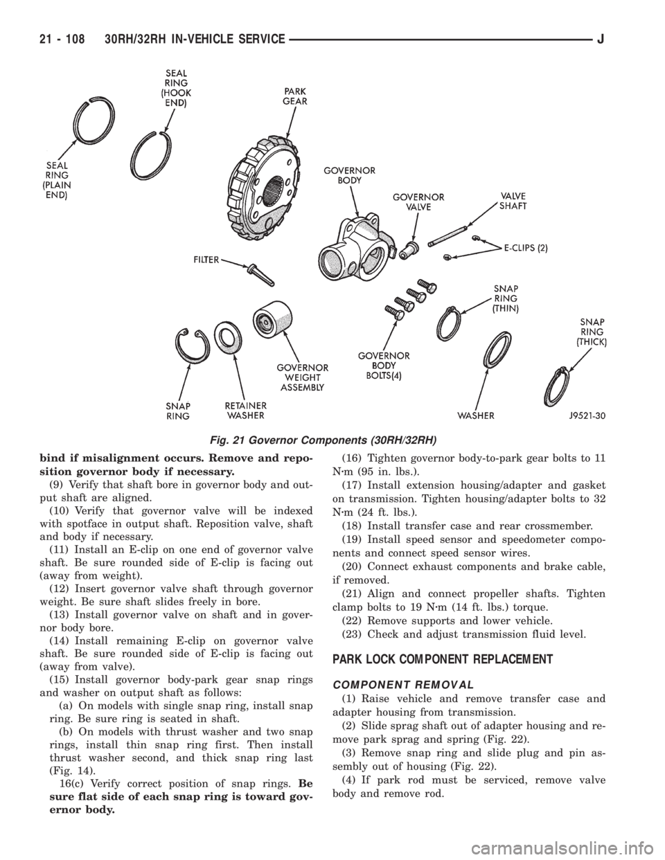
(11) Install an E-clip on one end of governor valve
shaft. Be sure rounded side of E-clip is facing out
(away from weight).
(12) Insert governor valve shaft through governor
weight. Be sure shaft slides freely in bore.
(13) Install governor valve on shaft and in gover-
nor body bore.
(14) Install remaining E-clip on governor valve
shaft. Be sure rounded side of E-clip is facing out
(away from valve).
(15) Install governor body-park gear snap rings
and washer on output shaft as follows:
(a) On models with single snap ring, install snap
ring. Be sure ring is seated in shaft.
(b) On models with thrust washer and two snap
rings, install thin snap ring first. Then install
thrust washer second, and thick snap ring last
(Fig. 14).
16(c) Verify correct position of snap rings.Be
sure flat side of each snap ring is toward gov-
ernor body.(16) Tighten governor body-to-park gear bolts to 11
Nzm (95 in. lbs.).
(17) Install extension housing/adapter and gasket
on transmission. Tighten housing/adapter bolts to 32
Nzm (24 ft. lbs.).
(18) Install transfer case and rear crossmember.
(19) Install speed sensor and speedometer compo-
nents and connect speed sensor wires.
(20) Connect exhaust components and brake cable,
if removed.
(21) Align and connect propeller shafts. Tighten
clamp bolts to 19 Nzm (14 ft. lbs.) torque.
(22) Remove supports and lower vehicle.
(23) Check and adjust transmission fluid level.
PARK LOCK COMPONENT REPLACEMENT
COMPONENT REMOVAL
(1) Raise vehicle and remove transfer case and
adapter housing from transmission.
(2) Slide sprag shaft out of adapter housing and re-
move park sprag and spring (Fig. 22).
(3) Remove snap ring and slide plug and pin as-
sembly out of housing (Fig. 22).
(4) If park rod must be serviced, remove valve
body and remove rod.
Fig. 21 Governor Components (30RH/32RH)
21 - 108 30RH/32RH IN-VEHICLE SERVICEJ
Page 1543 of 2198
ranges. Third gear ratio is 1:1. A separate planetary
gear set provides overdrive operation in fourth gear.
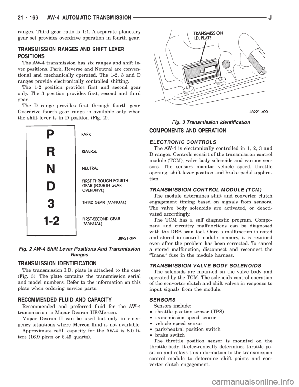
TRANSMISSION RANGES AND SHIFT LEVER
POSITIONS
The AW-4 transmission has six ranges and shift le-
ver positions. Park, Reverse and Neutral are conven-
tional and mechanically operated. The 1-2, 3 and D
ranges provide electronically controlled shifting.
The 1-2 position provides first and second gear
only. The 3 position provides first, second and third
gear.
The D range provides first through fourth gear.
Overdrive fourth gear range is available only when
the shift lever is in D position (Fig. 2).
TRANSMISSION IDENTIFICATION
The transmission I.D. plate is attached to the case
(Fig. 3). The plate contains the transmission serial
and model numbers. Refer to the information on this
plate when ordering service parts.
RECOMMENDED FLUID AND CAPACITY
Recommended and preferred fluid for the AW-4
transmission is Mopar Dexron IIE/Mercon.
Mopar Dexron II can be used but only in emer-
gency situations where Mercon fluid is not available.
Approximate refill capacity for the AW-4 is 8.0 li-
ters (16.9 pints or 8.45 quarts).
COMPONENTS AND OPERATION
ELECTRONIC CONTROLS
The AW-4 is electronically controlled in 1, 2, 3 and
D ranges. Controls consist of the transmission control
module (TCM), valve body solenoids and various sen-
sors. The sensors monitor vehicle speed, throttle
opening, shift lever position and brake pedal applica-
tion.
TRANSMISSION CONTROL MODULE (TCM)
The module determines shift and converter clutch
engagement timing based on signals from sensors.
The valve body solenoids are activated, or deacti-
vated accordingly.
The TCM has a self diagnostic program. Compo-
nent and circuitry malfunctions can be diagnosed
with the DRB scan tool. Once a malfunction is noted
and stored in control module memory, it is retained
even after the problem has been corrected. To cancel
a stored malfunction, disconnect and reconnect the
9Trans.9fuse in the module harness.
TRANSMISSION VALVE BODY SOLENOIDS
The solenoids are mounted on the valve body and
operated by the TCM. The solenoids control operation
of the converter clutch and shift valves in response to
input signals from the module.
SENSORS
Sensors include:
²throttle position sensor (TPS)
²transmission speed sensor
²vehicle speed sensor
²park/neutral position switch
²brake switch
The throttle position sensor is mounted on the
throttle body. It electronically determines throttle po-
sition and relays this information to the transmission
control module to determine shift points and con-
verter clutch engagement.
Fig. 2 AW-4 Shift Lever Positions And Transmission
Ranges
Fig. 3 Transmission Identification
21 - 166 AW-4 AUTOMATIC TRANSMISSIONJ
Page 1544 of 2198
The transmission speed sensor consists of a rotor
and magnet on the transmission output shaft and a
switch in the extension housing or adapter. The sen-
sor switch is activated each time the rotor and mag-
net complete one revolution. Sensor signals are sent
to the transmission control module.
The park/neutral position switch is mounted on the
valve body manual shaft. The switch signals shift
linkage and manual valve position to the transmis-
sion control module through an interconnecting har-
ness. The switch prevents engine starting in all gears
other than Park or Neutral.
The brake switch is in circuit with the torque con-
verter clutch solenoid. The switch disengages the
converter clutch whenever the brakes are applied.
The switch is mounted on the brake pedal bracket
and signals the transmission control module when
the pedal is pressed or released.
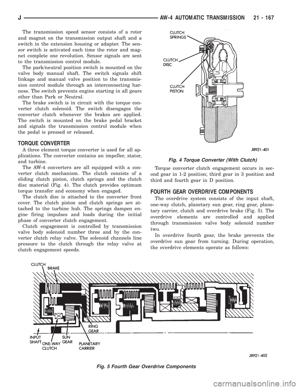
TORQUE CONVERTER
A three element torque converter is used for all ap-
plications. The converter contains an impeller, stator,
and turbine.
The AW-4 converters are all equipped with a con-
verter clutch mechanism. The clutch consists of a
sliding clutch piston, clutch springs and the clutch
disc material (Fig. 4). The clutch provides optimum
torque transfer and economy when engaged.
The clutch disc is attached to the converter front
cover. The clutch piston and clutch springs are at-
tached to the turbine hub. The springs dampen en-
gine firing impulses and loads during the initial
phase of converter clutch engagement.
Clutch engagement is controlled by transmission
valve body solenoid number three and by the con-
verter clutch relay valve. The solenoid channels line
pressure to the clutch through the relay valve at
clutch engagement speeds.Torque converter clutch engagement occurs in sec-
ond gear in 1-2 position; third gear in 3 position and
third and fourth gear in D position.
FOURTH GEAR OVERDRIVE COMPONENTS
The overdrive system consists of the input shaft,
one-way clutch, planetary sun gear, ring gear, plane-
tary carrier, clutch and overdrive brake (Fig. 5). The
overdrive elements are controlled and applied
through transmission valve body solenoid number
two.
In overdrive fourth gear, the brake prevents the
overdrive sun gear from turning. During operation,
the overdrive elements operate as follows:
Fig. 4 Torque Converter (With Clutch)
Fig. 5 Fourth Gear Overdrive Components
JAW-4 AUTOMATIC TRANSMISSION 21 - 167