dash JEEP CHEROKEE 1995 Service Repair Manual
[x] Cancel search | Manufacturer: JEEP, Model Year: 1995, Model line: CHEROKEE, Model: JEEP CHEROKEE 1995Pages: 2198, PDF Size: 82.83 MB
Page 32 of 2198
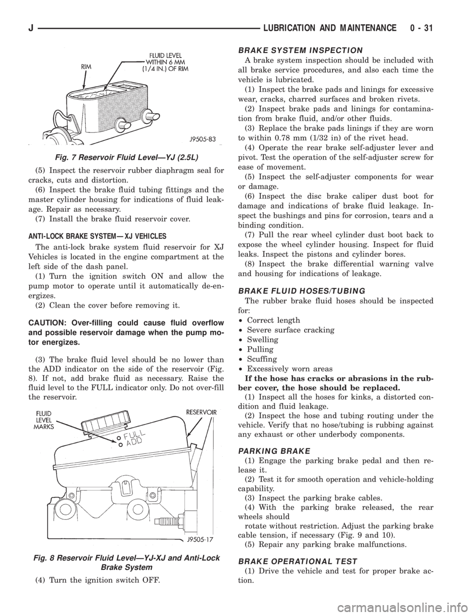
(5) Inspect the reservoir rubber diaphragm seal for
cracks, cuts and distortion.
(6) Inspect the brake fluid tubing fittings and the
master cylinder housing for indications of fluid leak-
age. Repair as necessary.
(7) Install the brake fluid reservoir cover.
ANTI-LOCK BRAKE SYSTEMÐXJ VEHICLES
The anti-lock brake system fluid reservoir for XJ
Vehicles is located in the engine compartment at the
left side of the dash panel.
(1) Turn the ignition switch ON and allow the
pump motor to operate until it automatically de-en-
ergizes.
(2) Clean the cover before removing it.
CAUTION: Over-filling could cause fluid overflow
and possible reservoir damage when the pump mo-
tor energizes.
(3) The brake fluid level should be no lower than
the ADD indicator on the side of the reservoir (Fig.
8). If not, add brake fluid as necessary. Raise the
fluid level to the FULL indicator only. Do not over-fill
the reservoir.
(4) Turn the ignition switch OFF.
BRAKE SYSTEM INSPECTION
A brake system inspection should be included with
all brake service procedures, and also each time the
vehicle is lubricated.
(1) Inspect the brake pads and linings for excessive
wear, cracks, charred surfaces and broken rivets.
(2) Inspect brake pads and linings for contamina-
tion from brake fluid, and/or other fluids.
(3) Replace the brake pads linings if they are worn
to within 0.78 mm (1/32 in) of the rivet head.
(4) Operate the rear brake self-adjuster lever and
pivot. Test the operation of the self-adjuster screw for
ease of movement.
(5) Inspect the self-adjuster components for wear
or damage.
(6) Inspect the disc brake caliper dust boot for
damage and indications of brake fluid leakage. In-
spect the bushings and pins for corrosion, tears and a
binding condition.
(7) Pull the rear wheel cylinder dust boot back to
expose the wheel cylinder housing. Inspect for fluid
leaks. Inspect the pistons and cylinder bores.
(8) Inspect the brake differential warning valve
and housing for indications of leakage.
BRAKE FLUID HOSES/TUBING
The rubber brake fluid hoses should be inspected
for:
²Correct length
²Severe surface cracking
²Swelling
²Pulling
²Scuffing
²Excessively worn areas
If the hose has cracks or abrasions in the rub-
ber cover, the hose should be replaced.
(1) Inspect all the hoses for kinks, a distorted con-
dition and fluid leakage.
(2) Inspect the hose and tubing routing under the
vehicle. Verify that no hose/tubing is rubbing against
any exhaust or other underbody components.
PARKING BRAKE
(1) Engage the parking brake pedal and then re-
lease it.
(2) Test it for smooth operation and vehicle-holding
capability.
(3) Inspect the parking brake cables.
(4) With the parking brake released, the rear
wheels should
rotate without restriction. Adjust the parking brake
cable tension, if necessary (Fig. 9 and 10).
(5) Repair any parking brake malfunctions.
BRAKE OPERATIONAL TEST
(1) Drive the vehicle and test for proper brake ac-
tion.
Fig. 7 Reservoir Fluid LevelÐYJ (2.5L)
Fig. 8 Reservoir Fluid LevelÐYJ-XJ and Anti-Lock
Brake System
JLUBRICATION AND MAINTENANCE 0 - 31
Page 159 of 2198
POWER BRAKE BOOSTERÐBRAKE PEDALÐBRAKELIGHT SWITCH
INDEX
page page
Brake Pedal Installation..................... 31
Brake Pedal Removal...................... 31
Brakelight Switch Adjustment................. 32
Brakelight Switch Installation................. 32
Brakelight Switch Removal.................. 32
General Information....................... 22
Power Brake Booster Installation (XJ with ABS) . . . 27
Power Brake Booster Installation (XJ Without ABS).. 30
Power Brake Booster Installation (YJ).......... 30
Power Brake Booster Operation.............. 23
Power Brake Booster Removal (XJ with ABS).... 24
Power Brake Booster Removal (XJ Without ABS) . . 29
Power Brake Booster Removal (YJ)............ 30
GENERAL INFORMATION
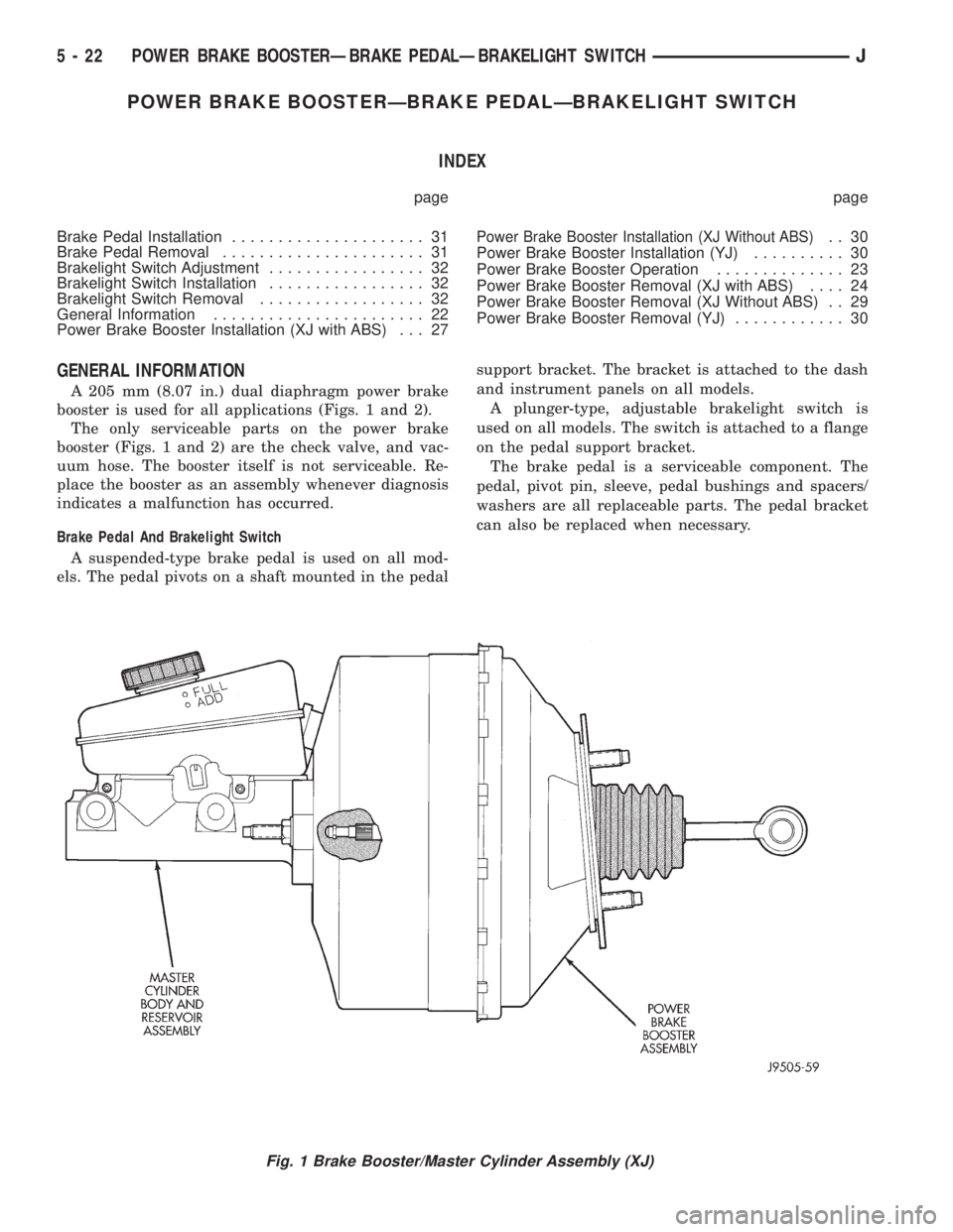
A 205 mm (8.07 in.) dual diaphragm power brake
booster is used for all applications (Figs. 1 and 2).
The only serviceable parts on the power brake
booster (Figs. 1 and 2) are the check valve, and vac-
uum hose. The booster itself is not serviceable. Re-
place the booster as an assembly whenever diagnosis
indicates a malfunction has occurred.
Brake Pedal And Brakelight Switch
A suspended-type brake pedal is used on all mod-
els. The pedal pivots on a shaft mounted in the pedalsupport bracket. The bracket is attached to the dash
and instrument panels on all models.
A plunger-type, adjustable brakelight switch is
used on all models. The switch is attached to a flange
on the pedal support bracket.
The brake pedal is a serviceable component. The
pedal, pivot pin, sleeve, pedal bushings and spacers/
washers are all replaceable parts. The pedal bracket
can also be replaced when necessary.
Fig. 1 Brake Booster/Master Cylinder Assembly (XJ)
5 - 22 POWER BRAKE BOOSTERÐBRAKE PEDALÐBRAKELIGHT SWITCHJ
Page 163 of 2198
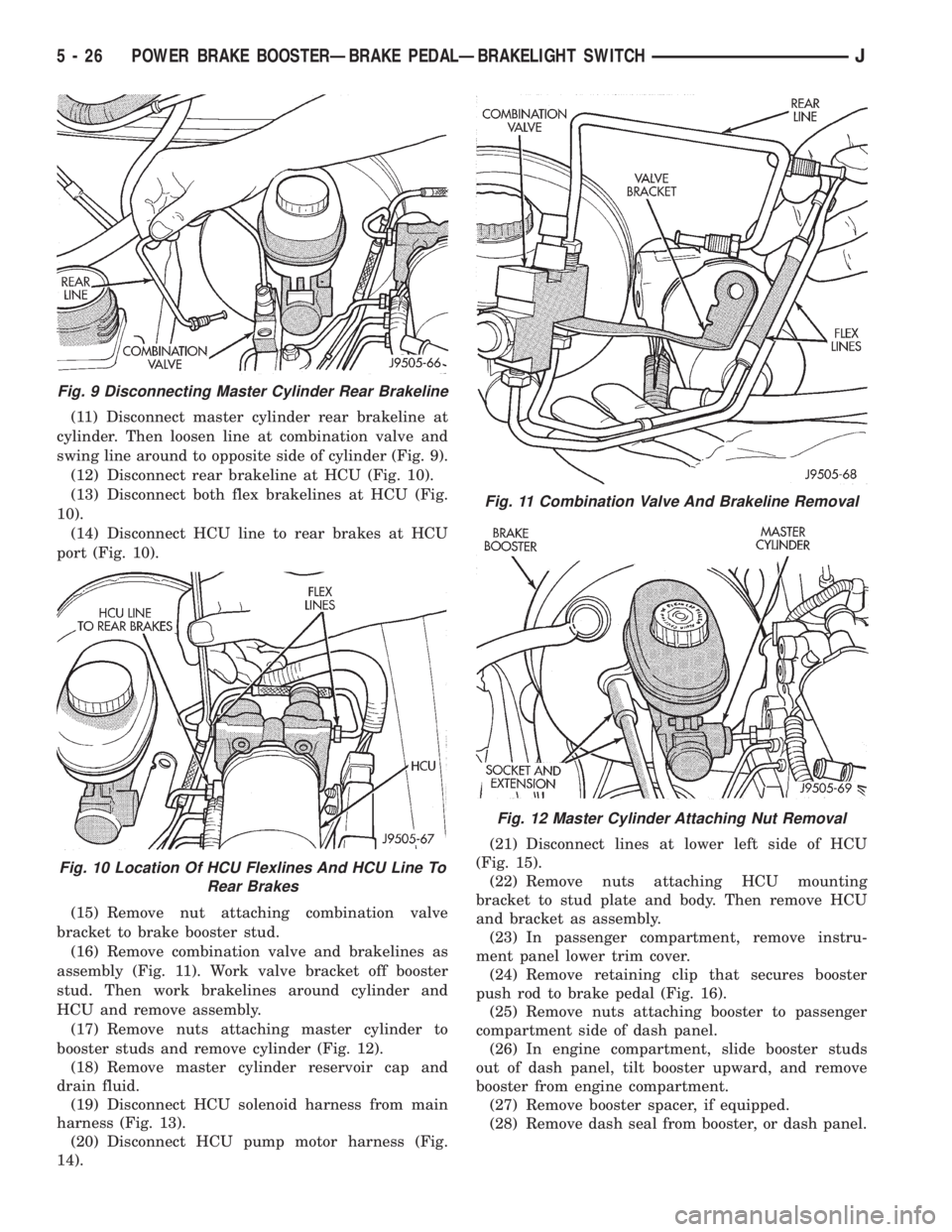
(11) Disconnect master cylinder rear brakeline at
cylinder. Then loosen line at combination valve and
swing line around to opposite side of cylinder (Fig. 9).
(12) Disconnect rear brakeline at HCU (Fig. 10).
(13) Disconnect both flex brakelines at HCU (Fig.
10).
(14) Disconnect HCU line to rear brakes at HCU
port (Fig. 10).
(15) Remove nut attaching combination valve
bracket to brake booster stud.
(16) Remove combination valve and brakelines as
assembly (Fig. 11). Work valve bracket off booster
stud. Then work brakelines around cylinder and
HCU and remove assembly.
(17) Remove nuts attaching master cylinder to
booster studs and remove cylinder (Fig. 12).
(18) Remove master cylinder reservoir cap and
drain fluid.
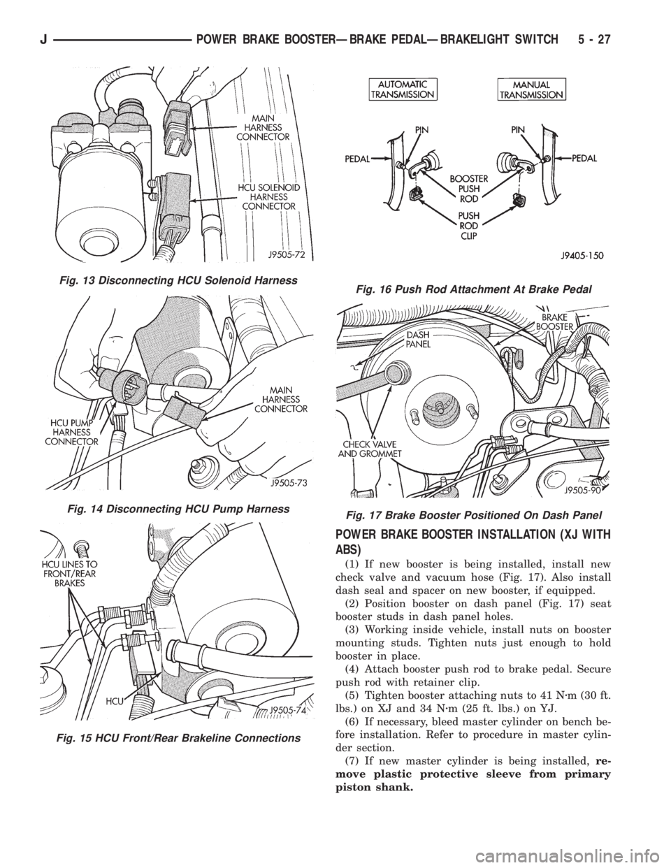
(19) Disconnect HCU solenoid harness from main
harness (Fig. 13).
(20) Disconnect HCU pump motor harness (Fig.
14).(21) Disconnect lines at lower left side of HCU
(Fig. 15).
(22) Remove nuts attaching HCU mounting
bracket to stud plate and body. Then remove HCU
and bracket as assembly.
(23) In passenger compartment, remove instru-
ment panel lower trim cover.
(24) Remove retaining clip that secures booster
push rod to brake pedal (Fig. 16).
(25) Remove nuts attaching booster to passenger
compartment side of dash panel.
(26) In engine compartment, slide booster studs
out of dash panel, tilt booster upward, and remove
booster from engine compartment.
(27) Remove booster spacer, if equipped.
(28) Remove dash seal from booster, or dash panel.
Fig. 9 Disconnecting Master Cylinder Rear Brakeline
Fig. 10 Location Of HCU Flexlines And HCU Line To
Rear Brakes
Fig. 11 Combination Valve And Brakeline Removal
Fig. 12 Master Cylinder Attaching Nut Removal
5 - 26 POWER BRAKE BOOSTERÐBRAKE PEDALÐBRAKELIGHT SWITCHJ
Page 164 of 2198
POWER BRAKE BOOSTER INSTALLATION (XJ WITH
ABS)
(1) If new booster is being installed, install new
check valve and vacuum hose (Fig. 17). Also install
dash seal and spacer on new booster, if equipped.
(2) Position booster on dash panel (Fig. 17) seat
booster studs in dash panel holes.
(3) Working inside vehicle, install nuts on booster
mounting studs. Tighten nuts just enough to hold
booster in place.
(4) Attach booster push rod to brake pedal. Secure
push rod with retainer clip.
(5) Tighten booster attaching nuts to 41 Nzm (30 ft.
lbs.) on XJ and 34 Nzm (25 ft. lbs.) on YJ.
(6) If necessary, bleed master cylinder on bench be-
fore installation. Refer to procedure in master cylin-
der section.
(7) If new master cylinder is being installed,re-
move plastic protective sleeve from primary
piston shank.
Fig. 13 Disconnecting HCU Solenoid Harness
Fig. 14 Disconnecting HCU Pump Harness
Fig. 15 HCU Front/Rear Brakeline Connections
Fig. 16 Push Rod Attachment At Brake Pedal
Fig. 17 Brake Booster Positioned On Dash Panel
JPOWER BRAKE BOOSTERÐBRAKE PEDALÐBRAKELIGHT SWITCH 5 - 27
Page 167 of 2198
(11) Remove nuts attaching booster to passenger
compartment side of dash panel.
(12) In engine compartment, slide booster studs
out of dash panel, tilt booster upward, and remove
booster from engine compartment.
(13) Remove dash seal from booster.
(14) If booster is only being removed for access to
other components, cover booster front opening with
clean shop towel.
POWER BRAKE BOOSTER INSTALLATION (XJ
WITHOUT ABS)
(1) If original booster is being installed, test check
valve with vacuum tool before booster installation.
Replace check valve if it will not hold vacuum.
(2) Install dash seal on booster.
(3) Align and position booster on dash panel (Fig.
17).
(4) In passenger compartment, install nuts that at-
tach booster to dash panel. Tighten nuts just enough
to hold booster in place.
(5) Slide booster push rod onto brake pedal. Then
secure push rod to pedal pin with retaining clip.
(6) Tighten booster attaching nuts to 41 Nzm (30 ft.
lbs.) on XJ and 34 Nzm (25 ft. lbs.) on YJ.
(7) Install instrument panel lower trim cover.
(8) If original master cylinder is being installed,
check condition of seal at rear of master cylinder
(Fig. 18). Clean and reposition seal if dislodged. Re-
place seal if cut, or torn.
(9) Clean cylinder mounting surface of brake
booster. Use shop towel wetted with brake cleaner for
this purpose. Dirt, grease, or similar materials will
prevent proper cylinder seating and could result in
vacuum leak.
(10) Align and install master cylinder on booster
studs. Tighten cylinder attaching nuts to 13-25 Nzm
(115-220 in. lbs.) torque.
(11) Connect vacuum hose to booster check valve.
(12) Connect and secure brakelines to combination
valve and master cylinder. Start all brakeline fittings
by hand to avoid cross threading.
(13) If combination valve has integral bracket, po-
sition bracket on booster studs. Then install and
tighten bracket attaching nuts to 13-25 Nzm (115-220
in. lbs.) torque.
(14) Connect wire to combination valve switch.
(15) Top off master cylinder fluid level.
(16) Bleed brakes. Refer to procedures in section
on brake bleeding.
(17) Install engine air cleaner and hoses.
(18) Verify proper brake operation before moving
vehicle.
POWER BRAKE BOOSTER REMOVAL (YJ)
(1) Disconnect brakelines at master cylinder. Then
loosen lines at combination valve and move lines
away from cylinder.
(2) Remove nuts master cylinder to booster studs.
(3) If combination valve has integral bracket, slide
bracket off studs and move valve aside.
(4) Remove master cylinder. Slide cylinder off
studs and remove it from engine compartment.
(5) Working under instrument panel, remove re-
tainer clip that secures booster push rod to brake
pedal.
(6) Disconnect vacuum hose at booster check valve.
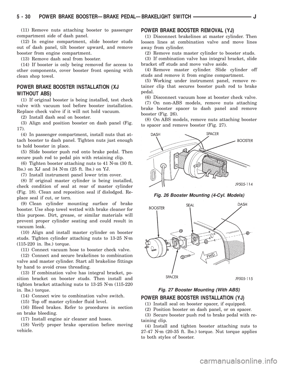
(7) On non-ABS models, remove nuts attaching
brake booster spacer to dash panel and remove
booster (Fig. 26).
(8) On ABS models, remove nuts attaching booster
to spacer and remove booster (Fig. 27).
POWER BRAKE BOOSTER INSTALLATION (YJ)
(1) Install seal on booster spacer, if equipped.
(2) Position booster on dash panel, or on spacer.
(3) Secure booster push rod to brake pedal with re-
taining clip.
(4) Install and tighten booster attaching nuts to
27-47 Nzm (20-35 ft. lbs.) torque. Nut torque applies
to both styles of booster.
Fig. 26 Booster Mounting (4-Cyl. Models)
Fig. 27 Booster Mounting (With ABS)
5 - 30 POWER BRAKE BOOSTERÐBRAKE PEDALÐBRAKELIGHT SWITCHJ
Page 168 of 2198
(5) Connect vacuum hose to brake booster check
valve.
(6) Install master cylinder and combination valve.
(7) Bleed brakes. Then tighten brakeline fittings to
15-18 Nzm (130-160 in. lbs.) at master cylinder and
18-24 Nzm (160-210 in. lbs.) at combination valve.
BRAKE PEDAL REMOVAL
(1) Remove lower trim panel and A/C duct if nec-
essary.
(2) Remove steering column lower trim panel and
bezel.(3) Remove necessary dash panel-to-instrument
panel brace rods.
(4) Disconnect and remove brakelight switch.
(5) Remove retainer clip securing booster push rod
to pedal (Fig. 16).
(6) Remove nut securing pedal shaft in support
bracket.
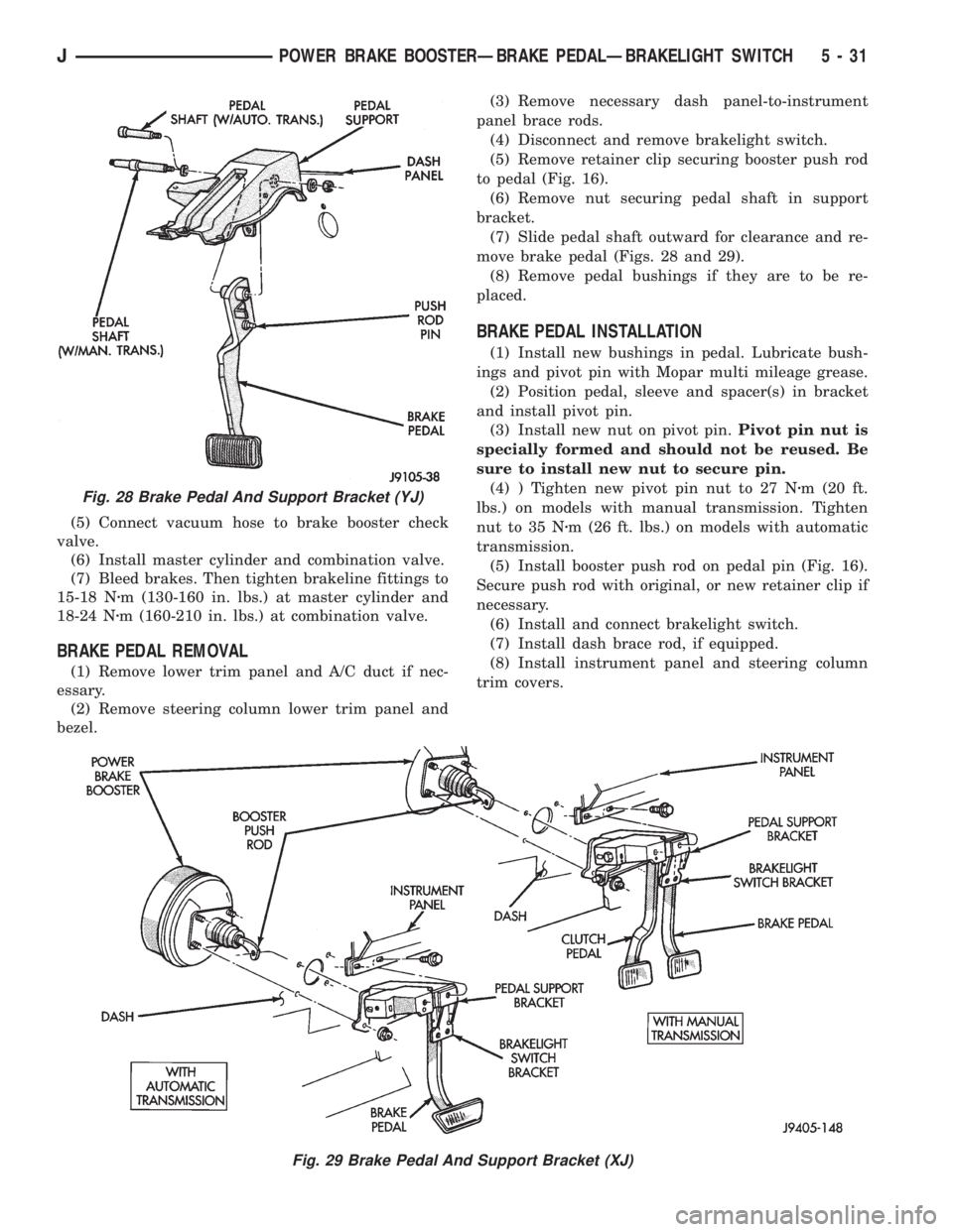
(7) Slide pedal shaft outward for clearance and re-
move brake pedal (Figs. 28 and 29).
(8) Remove pedal bushings if they are to be re-
placed.
BRAKE PEDAL INSTALLATION
(1) Install new bushings in pedal. Lubricate bush-
ings and pivot pin with Mopar multi mileage grease.
(2) Position pedal, sleeve and spacer(s) in bracket
and install pivot pin.
(3) Install new nut on pivot pin.Pivot pin nut is
specially formed and should not be reused. Be
sure to install new nut to secure pin.
(4) ) Tighten new pivot pin nut to 27 Nzm (20 ft.
lbs.) on models with manual transmission. Tighten
nut to 35 Nzm (26 ft. lbs.) on models with automatic
transmission.
(5) Install booster push rod on pedal pin (Fig. 16).
Secure push rod with original, or new retainer clip if
necessary.
(6) Install and connect brakelight switch.
(7) Install dash brace rod, if equipped.
(8) Install instrument panel and steering column
trim covers.
Fig. 28 Brake Pedal And Support Bracket (YJ)
Fig. 29 Brake Pedal And Support Bracket (XJ)
JPOWER BRAKE BOOSTERÐBRAKE PEDALÐBRAKELIGHT SWITCH 5 - 31
Page 177 of 2198
CAUTION: The mercury switch (inside the accelera-
tion switch), will not function properly if the switch
is mispositioned. Verify that the switch locating ar-
row is pointing to the front of the vehicle.
(2) Position switch in mounting bracket.
(3) Install and tighten switch attaching screws to
2-4 Nzm (17-32 in. lbs.) torque.
(4) Connect harness to switch. Be sure harness
connecter is firmly seated.
(5) Move seat back to normal position.
ECU REMOVAL (XJ MODELS)
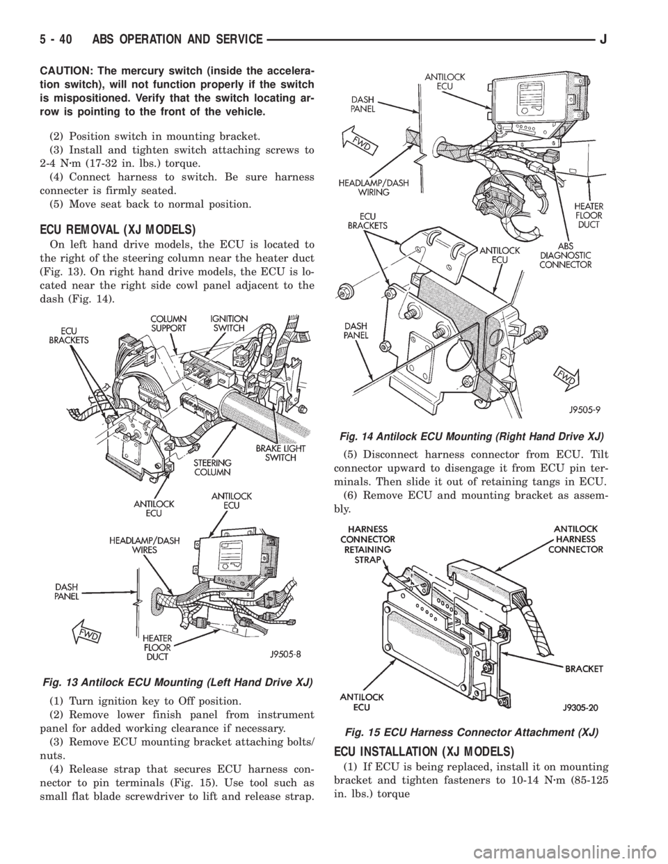
On left hand drive models, the ECU is located to
the right of the steering column near the heater duct
(Fig. 13). On right hand drive models, the ECU is lo-
cated near the right side cowl panel adjacent to the
dash (Fig. 14).
(1) Turn ignition key to Off position.
(2) Remove lower finish panel from instrument
panel for added working clearance if necessary.
(3) Remove ECU mounting bracket attaching bolts/
nuts.
(4) Release strap that secures ECU harness con-
nector to pin terminals (Fig. 15). Use tool such as
small flat blade screwdriver to lift and release strap.(5) Disconnect harness connector from ECU. Tilt
connector upward to disengage it from ECU pin ter-
minals. Then slide it out of retaining tangs in ECU.
(6) Remove ECU and mounting bracket as assem-
bly.
ECU INSTALLATION (XJ MODELS)
(1) If ECU is being replaced, install it on mounting
bracket and tighten fasteners to 10-14 Nzm (85-125
in. lbs.) torque
Fig. 13 Antilock ECU Mounting (Left Hand Drive XJ)
Fig. 14 Antilock ECU Mounting (Right Hand Drive XJ)
Fig. 15 ECU Harness Connector Attachment (XJ)
5 - 40 ABS OPERATION AND SERVICEJ
Page 178 of 2198
(2) Align and attach harness connector to ECU.
Slide connector into engagement with tangs on ECU.
Then tilt connector downward and into engagement
with ECU pin terminals. Exercise care as pin termi-
nals can be damaged if connector is forced into place.
(3) Connect harness to security alarm module, if
equipped.
(4) Position ECU bracket under instrument panel.
(5) Install and tighten ECU mounting bracket
bolts/nuts to 8-14 Nzm (75- 125 in. lbs.) torque.
(6) Install trim panel on instrument panel, if re-
moved.
ECU REMOVAL/INSTALLATION (YJ MODELS)
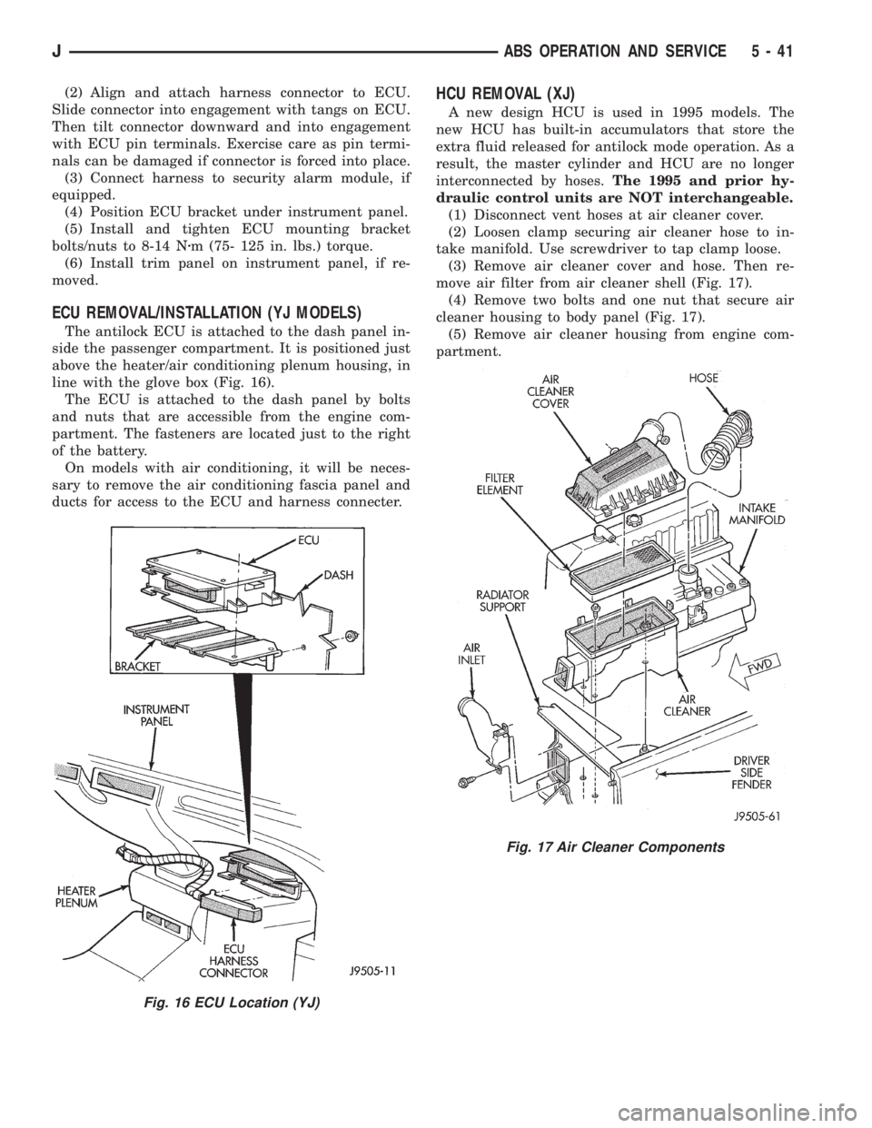
The antilock ECU is attached to the dash panel in-
side the passenger compartment. It is positioned just
above the heater/air conditioning plenum housing, in
line with the glove box (Fig. 16).
The ECU is attached to the dash panel by bolts
and nuts that are accessible from the engine com-
partment. The fasteners are located just to the right
of the battery.
On models with air conditioning, it will be neces-
sary to remove the air conditioning fascia panel and
ducts for access to the ECU and harness connecter.
HCU REMOVAL (XJ)
A new design HCU is used in 1995 models. The
new HCU has built-in accumulators that store the
extra fluid released for antilock mode operation. As a
result, the master cylinder and HCU are no longer
interconnected by hoses.The 1995 and prior hy-
draulic control units are NOT interchangeable.
(1) Disconnect vent hoses at air cleaner cover.
(2) Loosen clamp securing air cleaner hose to in-
take manifold. Use screwdriver to tap clamp loose.
(3) Remove air cleaner cover and hose. Then re-
move air filter from air cleaner shell (Fig. 17).
(4) Remove two bolts and one nut that secure air
cleaner housing to body panel (Fig. 17).
(5) Remove air cleaner housing from engine com-
partment.
Fig. 16 ECU Location (YJ)
Fig. 17 Air Cleaner Components
JABS OPERATION AND SERVICE 5 - 41
Page 198 of 2198
secondary brakeshoes move the shoes directly into
contact with the drum braking surface. The actuating
levers are interconnected by a system of cables and a
tensioner mechanism. The tensioner mechanism con-
trols parking brake adjustment.
A parking brake switch is used on all models. It is
mounted on the parking brake lever or foot pedal and
is actuated by movement of the lever/pedal. The
switch, which is in circuit with the red warning light
in the dash, will illuminate the warning light when-
ever the parking brakes are applied.
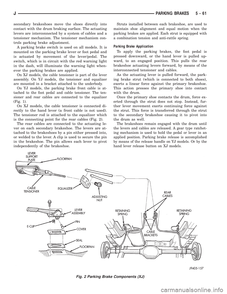
On XJ models, the cable tensioner is part of the lever
assembly. On YJ models, the tensioner and equalizer
are mounted in a bracket attached to the underbody.
On YJ models, the parking brake front cable is at-
tached to the foot pedal and cable tensioner. The ten-
sioner and rear cables are connected to the equalizer
(Fig. 1).
On XJ models, the cable tensioner is connected di-
rectly to the hand lever (a front cable is not used).
The tensioner rod is attached to the equalizer which
is the connecting point for the rear cables (Fig. 2).
The rear cables are connected to the actuating le-
ver on each secondary brakeshoe. The levers are at-
tached to the brakeshoes by a pin either pressed into,
or welded to the lever. A clip is used to secure the pin
in the brakeshoe. The pin allows each lever to pivot
independently of the brakeshoe.
Struts installed between each brakeshoe, are used to
maintain shoe alignment and equal motion when the
parking brakes are applied. Each strut is equipped with
a combination tension and anti-rattle spring.
Parking Brake Application
To apply the parking brakes, the foot pedal is
pressed downward, or the hand lever is pulled up-
ward, to an engaged position. This pulls the rear
brakeshoe actuating levers forward, by means of the
interconnected tensioner and cables.
As the actuating lever is pulled forward, the park-
ing brake strut (which is connected to both shoes),
exerts a linear force against the primary brakeshoe.
This action presses the primary shoe into contact
with the drum.
Once the primary shoe contacts the drum, force ex-
erted through the strut does not stop. Instead, fur-
ther lever movement exerts continuing force against
the strut. This force is transferred through the strut
to the secondary brakeshoe causing it to pivot into
the drum as well.
The brakeshoes remain engaged with the drum until
the levers and cables are released. A gear type ratchet-
ing mechanism is used to hold the pedal or lever in an
applied position. Parking brake release is accomplished
by means of the release handle on YJ models. Or by the
hand lever release button on XJ models.
Fig. 2 Parking Brake Components (XJ)
JPARKING BRAKES 5 - 61
Page 203 of 2198
PARKING BRAKE CABLE TENSIONER
REPLACEMENT (XJ)
(1) Raise vehicle.
(2) Remove adjuster nut from tensioner rod. Secure
equalizer and cables to nearby chassis component
with wire.
(3) Remove nuts attaching lever assembly to sup-
port plate and floorpan.
(4) Lower vehicle.
(5) Remove console components and lever assembly
cover.
(6) Remove lever and tensioner assembly.
(7) Move cover and boot for access to tensioner re-
taining pin.
(8) Remove E-clip and pin that attach tensioner to
lever arm (Fig. 4).
(9) Remove tensioner from cover.
(10) Transfer boot to new tensioner if necessary.
(11) Attach tensioner to lever arm with pin and E-
clip.
(12) Verify that E-clip is fully engaged in pin (Fig.
4).
(13) Align cover and seal on lever flange.
(14) Verify that tensioner boot is seated in cover
(Fig. 6).
(15) Install assembled lever and tensioner in floor-
pan.
(16) Install necessary console components.
(17) Adjust parking brakes as described in this sec-
tion.
PARKING BRAKE PEDAL REMOVAL (YJ)
(1) Raise vehicle.
(2) Loosen equalizer nuts until front cable is slack
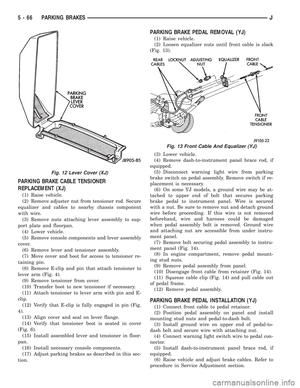
(Fig. 13).
(3) Lower vehicle.
(4) Remove dash-to-instrument panel brace rod, if
equipped.
(5) Disconnect warning light wire from parking
brake switch on pedal assembly. Remove switch if re-
placement is necessary.
(6) On some YJ models, a ground wire may be at-
tached to upper end of bolt that secures parking
brake pedal to instrument panel. Wire is secured
with a nut. Be sure to remove nut and detach ground
wire before proceeding. If this wire is not removed
beforehand, wire and harness could be damaged
when pedal assembly bolt is removed. Ground wire
and attaching nut are accessible from under instru-
ment panel.
(7) Remove bolt securing pedal assembly to instru-
ment panel (Fig. 14).
(8) In engine compartment, remove pedal mount-
ing stud nuts.
(9) Remove pedal assembly from panel.
(10) Disengage front cable from retainer (Fig. 14).
(11) Squeeze cable clip (Fig. 14) and pull cable out
of pedal frame.
(12) Remove pedal assembly.
PARKING BRAKE PEDAL INSTALLATION (YJ)
(1) Connect front cable to pedal retainer.
(2) Position pedal assembly on panel and install
mounting stud nuts and pedal-to-dash bolt.
(3) Install ground wire on upper end of pedal-to-
dash bolt and secure wire with attaching nut.
(4) Connect warning light switch wire to pedal con-
nector.
(5) Install dash-to-instrument panel brace rod, if
equipped.
(6) Raise vehicle and adjust brake cables. Refer to
procedure in Service Adjustment section.
Fig. 12 Lever Cover (XJ)
Fig. 13 Front Cable And Equalizer (YJ)
5 - 66 PARKING BRAKESJ