distributor install JEEP CHEROKEE 1995 Service Repair Manual
[x] Cancel search | Manufacturer: JEEP, Model Year: 1995, Model line: CHEROKEE, Model: JEEP CHEROKEE 1995Pages: 2198, PDF Size: 82.83 MB
Page 3 of 2198
CLASSIFICATION OF LUBRICANTS
Lubricating fluids and chassis lubricants are clas-
sified according to standards recommended by the:
²Society of Automotive Engineers (SAE)
²American Petroleum Institute (API)
²National Lubricating Grease Institute (NLGI)
ENGINE OIL
API CERTIFICATION MARK
For maximum engine protection during all driving
conditions, install an engine oil that contains the API
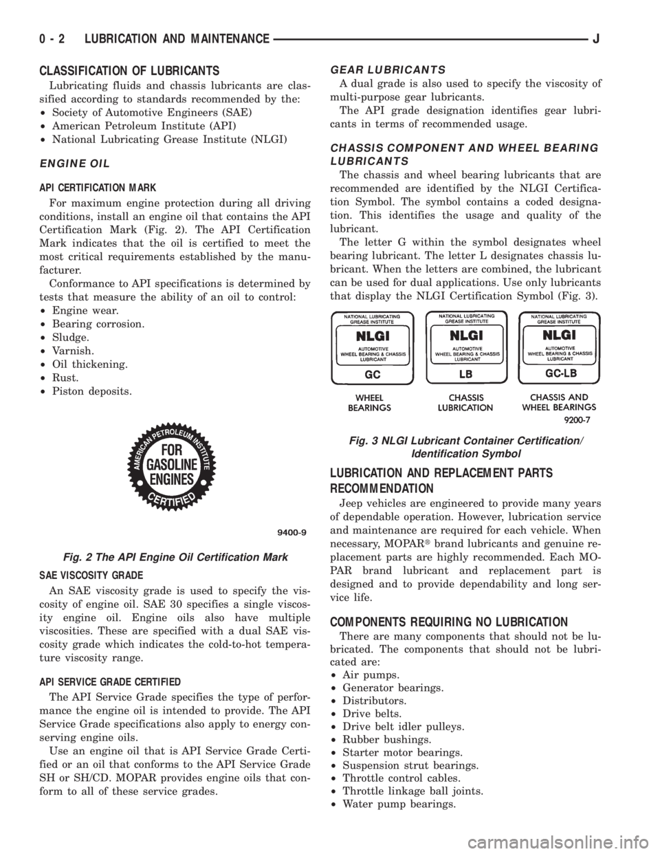
Certification Mark (Fig. 2). The API Certification
Mark indicates that the oil is certified to meet the
most critical requirements established by the manu-
facturer.
Conformance to API specifications is determined by
tests that measure the ability of an oil to control:
²Engine wear.
²Bearing corrosion.
²Sludge.
²Varnish.
²Oil thickening.
²Rust.
²Piston deposits.
SAE VISCOSITY GRADE
An SAE viscosity grade is used to specify the vis-
cosity of engine oil. SAE 30 specifies a single viscos-
ity engine oil. Engine oils also have multiple
viscosities. These are specified with a dual SAE vis-
cosity grade which indicates the cold-to-hot tempera-
ture viscosity range.
API SERVICE GRADE CERTIFIED
The API Service Grade specifies the type of perfor-
mance the engine oil is intended to provide. The API
Service Grade specifications also apply to energy con-
serving engine oils.
Use an engine oil that is API Service Grade Certi-
fied or an oil that conforms to the API Service Grade
SH or SH/CD. MOPAR provides engine oils that con-
form to all of these service grades.
GEAR LUBRICANTS
A dual grade is also used to specify the viscosity of
multi-purpose gear lubricants.
The API grade designation identifies gear lubri-
cants in terms of recommended usage.
CHASSIS COMPONENT AND WHEEL BEARING
LUBRICANTS
The chassis and wheel bearing lubricants that are
recommended are identified by the NLGI Certifica-
tion Symbol. The symbol contains a coded designa-
tion. This identifies the usage and quality of the
lubricant.
The letter G within the symbol designates wheel
bearing lubricant. The letter L designates chassis lu-
bricant. When the letters are combined, the lubricant
can be used for dual applications. Use only lubricants
that display the NLGI Certification Symbol (Fig. 3).
LUBRICATION AND REPLACEMENT PARTS
RECOMMENDATION
Jeep vehicles are engineered to provide many years
of dependable operation. However, lubrication service
and maintenance are required for each vehicle. When
necessary, MOPARtbrand lubricants and genuine re-
placement parts are highly recommended. Each MO-
PAR brand lubricant and replacement part is
designed and to provide dependability and long ser-
vice life.
COMPONENTS REQUIRING NO LUBRICATION
There are many components that should not be lu-
bricated. The components that should not be lubri-
cated are:
²Air pumps.
²Generator bearings.
²Distributors.
²Drive belts.
²Drive belt idler pulleys.
²Rubber bushings.
²Starter motor bearings.
²Suspension strut bearings.
²Throttle control cables.
²Throttle linkage ball joints.
²Water pump bearings.
Fig. 2 The API Engine Oil Certification Mark
Fig. 3 NLGI Lubricant Container Certification/
Identification Symbol
0 - 2 LUBRICATION AND MAINTENANCEJ
Page 16 of 2198
ENGINE MAINTENANCE
INDEX
page page
Accessory Drive Belt....................... 21
Air Cleaner Element....................... 18
Air-Conditioner Compressor.................. 21
Battery................................. 20
Crankcase Ventilation System................ 19
Emission Control System................... 20
Engine Break-In.......................... 15
Engine Cooling System..................... 18
Engine Oil.............................. 15Engine Oil Change and Filter Replacement...... 16
Engine Oil Filter.......................... 17
Engine Supports.......................... 21
Exhaust System.......................... 21
Fuel Filter............................... 19
Fuel Usage StatementÐGas Engines.......... 19
Ignition Cables, Distributor Cap and Rotor....... 20
Rubber and Plastic Component Inspection....... 20
Spark Plugs............................. 20
ENGINE BREAK-IN
CAUTION: Wide open throttle operation in low
gears, before engine break-in period is complete,
can damage engine.
After first starting a new engine, allow it to idle for
15 seconds before shifting into a drive gear. Also:
²Drive the vehicle at varying speeds less than 88
km/h (55 mph) for the first 480 km (300 miles).
²Avoid fast acceleration and sudden stops.
²Do not drive at full-throttle for extended periods of
time.
²Do not drive at constant speeds.
²Do not idle the engine excessively.
A special break-in engine oil is not required. The
original engine oil installed is a high quality, energy
conserving lubricant. Special break-in oils are not
recommended. These oils could interfere with the
normal piston ring seating process.
New engines tend to consume more fuel and oil un-
til after the break-in period has ended.
ENGINE OIL
WARNING: NEW OR USED ENGINE OIL CAN BE IR-
RITATING TO THE SKIN. AVOID PROLONGED OR
REPEATED SKIN CONTACT WITH ENGINE OIL.
CONTAMINANTS IN USED ENGINE OIL, CAUSED BY
INTERNAL COMBUSTION, CAN BE HAZARDOUS TO
YOUR HEALTH. THOROUGHLY WASH EXPOSED
SKIN WITH SOAP AND WATER.
DO NOT WASH SKIN WITH GASOLINE, DIESEL
FUEL, THINNER, OR SOLVENTS, HEALTH PROB-
LEMS CAN RESULT.
DO NOT POLLUTE, DISPOSE OF USED ENGINE
OIL PROPERLY. CONTACT YOUR DEALER OR GOV-
ERNMENT AGENCY FOR LOCATION OF COLLEC-
TION CENTER IN YOUR AREA.
ENGINE OIL SPECIFICATION
CAUTION: Do not use non-detergent or straight
mineral oil when adding or changing crankcase lu-
bricant. Engine failure can result.
API SERVICE GRADE CERTIFIED
Use an engine oil that is API Service Grade Certi-
fied or an oil that conforms to the API Service Grade
SH or SH/CD. MOPAR provides engine oils that con-
form to all of these service grades.
SAE VISCOSITY
An SAE viscosity grade is used to specify the vis-
cosity grade of engine oil. SAE 30 specifies a single
viscosity engine oil. Engine oils also have multiple
viscosities. These are specified with a dual SAE vis-
cosity grade which indicates the cold-to-hot tempera-
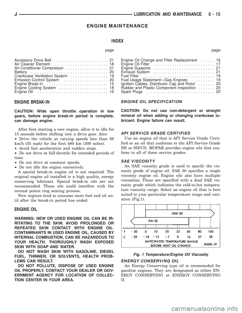
ture viscosity range. Select an engine oil that is best
suited to your particular temperature range and vari-
ation (Fig.1).
ENERGY CONSERVING OIL
An Energy Conserving type oil is recommeded for
gasoline engines. They are designated as either EN-
ERGY CONSERVING or ENERGY CONSERVING
II.
Fig. 1 Temperature/Engine Oil Viscosity
JLUBRICATION AND MAINTENANCE 0 - 15
Page 312 of 2198
IGNITION SYSTEMS
CONTENTS
page page
COMPONENT IDENTIFICATION/SYSTEM
OPERATION........................... 1
COMPONENT REMOVAL/INSTALLATION...... 17
DIAGNOSTICS/SERVICE PROCEDURES....... 6IGNITION SWITCHÐXJ MODELS........... 26
IGNITION SWITCHÐYJ MODELS........... 29
SPECIFICATIONS........................ 32
COMPONENT IDENTIFICATION/SYSTEM OPERATION
INDEX
page page
Automatic Shutdown (ASD) Relay.............. 1
Camshaft Position Sensor.................... 2
Crankshaft Position Sensor................... 3
Distributors............................... 4
Engine Coolant Temperature Sensor............ 5
General Information........................ 1Ignition Coil.............................. 4
Intake Manifold Air Temperature Sensor.......... 5
Manifold Absolute Pressure (MAP) Sensor........ 5
Oxygen (O2S) Sensor....................... 5
Powertrain Control Module (PCM).............. 5
Throttle Position Sensor..................... 5
GENERAL INFORMATION
Throughout this group, references are made to par-
ticular vehicle models by alphabetical designation
(XJ or YJ) or by the particular vehicle nameplate. A
chart showing a breakdown of alphabetical designa-
tions is included in the Introduction group at the be-
ginning of this manual.
This section of the group, Component Identifica-
tion/System Operation, will discuss ignition system
operation and will identify ignition system compo-
nents.
For diagnostic procedures and adjustments, refer to
the Diagnostics/Service Procedures section of this
group.
For removal and installation of ignition system
components, refer to the Component Removal/Instal-
lation section of this group.
For other useful information, refer to On-Board Di-
agnostics in the General Diagnosis sections of Group
14, Fuel System in this manual.
For operation of the DRB Scan Tool, refer to the
appropriate Powertrain Diagnostic Procedures ser-
vice manual.
An Ignition specifications section is included at the
end of this group. A general Maintenance Schedule
(mileage intervals) for ignition related items can be
found in Group 0, Lubrication and Maintenance. This
schedule can also be found in the Owners Manual.
IGNITION SYSTEMS
A multi-port, fuel injected engine is used on all
models. The ignition system is controlled by the pow-
ertrain control module (PCM) on all engines. The
PCM was formerly referred to as the SBEC or engine
controller.
The ignition system consists of:
²Spark plugs
²Ignition coil
²Secondary ignition cables
²Distributor (contains rotor and camshaft position
sensor)
²Powertrain control module (PCM)
²Crankshaft position sensor
AUTOMATIC SHUTDOWN (ASD) RELAY
The automatic shutdown (ASD) relay is located in
the power distribution center (PDC) near the battery
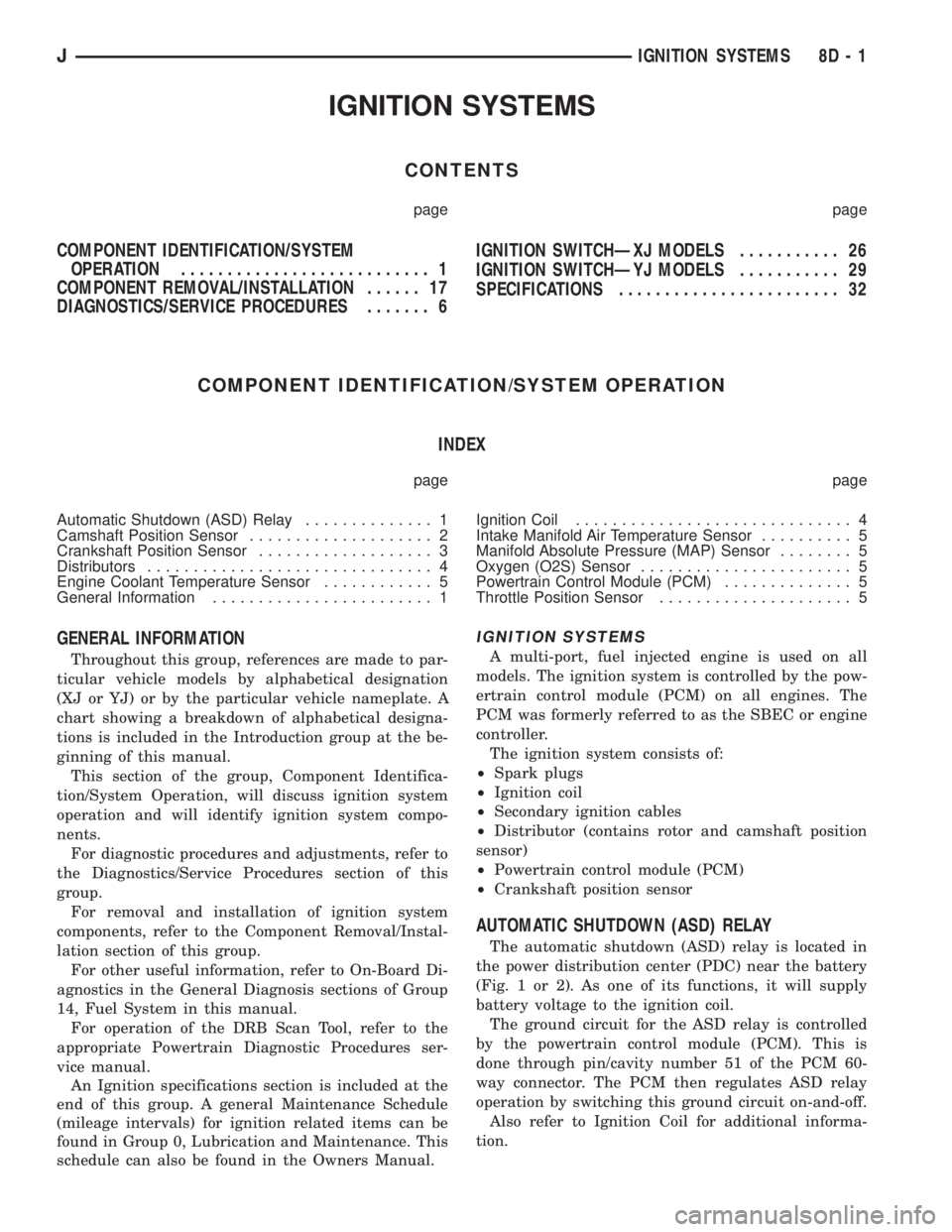
(Fig. 1 or 2). As one of its functions, it will supply
battery voltage to the ignition coil.
The ground circuit for the ASD relay is controlled
by the powertrain control module (PCM). This is
done through pin/cavity number 51 of the PCM 60-
way connector. The PCM then regulates ASD relay
operation by switching this ground circuit on-and-off.
Also refer to Ignition Coil for additional informa-
tion.
JIGNITION SYSTEMS 8D - 1
Page 313 of 2198
CAMSHAFT POSITION SENSOR
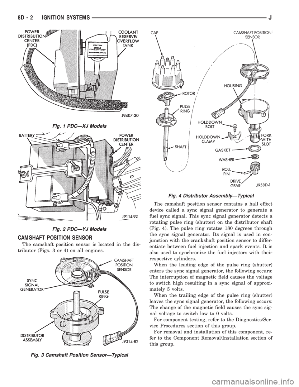
The camshaft position sensor is located in the dis-
tributor (Figs. 3 or 4) on all engines.The camshaft position sensor contains a hall effect
device called a sync signal generator to generate a
fuel sync signal. This sync signal generator detects a
rotating pulse ring (shutter) on the distributor shaft
(Fig. 4). The pulse ring rotates 180 degrees through
the sync signal generator. Its signal is used in con-
junction with the crankshaft position sensor to differ-
entiate between fuel injection and spark events. It is
also used to synchronize the fuel injectors with their
respective cylinders.
When the leading edge of the pulse ring (shutter)
enters the sync signal generator, the following occurs:
The interruption of magnetic field causes the voltage
to switch high resulting in a sync signal of approxi-
mately 5 volts.
When the trailing edge of the pulse ring (shutter)
leaves the sync signal generator, the following occurs:
The change of the magnetic field causes the sync sig-
nal voltage to switch low to 0 volts.
For component testing, refer to the Diagnostics/Ser-
vice Procedures section of this group.
For removal and installation of this component, re-
fer to the Component Removal/Installation section of
this group.
Fig. 1 PDCÐXJ Models
Fig. 2 PDCÐYJ Models
Fig. 3 Camshaft Position SensorÐTypical
Fig. 4 Distributor AssemblyÐTypical
8D - 2 IGNITION SYSTEMSJ
Page 315 of 2198
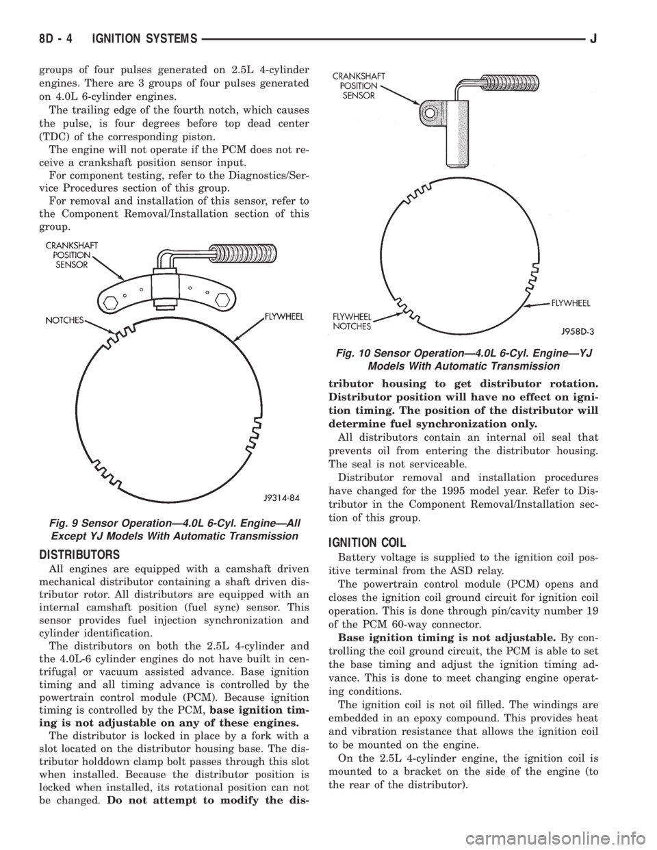
groups of four pulses generated on 2.5L 4-cylinder
engines. There are 3 groups of four pulses generated
on 4.0L 6-cylinder engines.
The trailing edge of the fourth notch, which causes
the pulse, is four degrees before top dead center
(TDC) of the corresponding piston.
The engine will not operate if the PCM does not re-
ceive a crankshaft position sensor input.
For component testing, refer to the Diagnostics/Ser-
vice Procedures section of this group.
For removal and installation of this sensor, refer to
the Component Removal/Installation section of this
group.
DISTRIBUTORS
All engines are equipped with a camshaft driven
mechanical distributor containing a shaft driven dis-
tributor rotor. All distributors are equipped with an
internal camshaft position (fuel sync) sensor. This
sensor provides fuel injection synchronization and
cylinder identification.
The distributors on both the 2.5L 4-cylinder and
the 4.0L-6 cylinder engines do not have built in cen-
trifugal or vacuum assisted advance. Base ignition
timing and all timing advance is controlled by the
powertrain control module (PCM). Because ignition
timing is controlled by the PCM,base ignition tim-
ing is not adjustable on any of these engines.
The distributor is locked in place by a fork with a
slot located on the distributor housing base. The dis-
tributor holddown clamp bolt passes through this slot
when installed. Because the distributor position is
locked when installed, its rotational position can not
be changed.Do not attempt to modify the dis-tributor housing to get distributor rotation.
Distributor position will have no effect on igni-
tion timing. The position of the distributor will
determine fuel synchronization only.
All distributors contain an internal oil seal that
prevents oil from entering the distributor housing.
The seal is not serviceable.
Distributor removal and installation procedures
have changed for the 1995 model year. Refer to Dis-
tributor in the Component Removal/Installation sec-
tion of this group.
IGNITION COIL
Battery voltage is supplied to the ignition coil pos-
itive terminal from the ASD relay.
The powertrain control module (PCM) opens and
closes the ignition coil ground circuit for ignition coil
operation. This is done through pin/cavity number 19
of the PCM 60-way connector.
Base ignition timing is not adjustable.By con-
trolling the coil ground circuit, the PCM is able to set
the base timing and adjust the ignition timing ad-
vance. This is done to meet changing engine operat-
ing conditions.
The ignition coil is not oil filled. The windings are
embedded in an epoxy compound. This provides heat
and vibration resistance that allows the ignition coil
to be mounted on the engine.
On the 2.5L 4-cylinder engine, the ignition coil is
mounted to a bracket on the side of the engine (to
the rear of the distributor).
Fig. 9 Sensor OperationÐ4.0L 6-Cyl. EngineÐAll
Except YJ Models With Automatic Transmission
Fig. 10 Sensor OperationÐ4.0L 6-Cyl. EngineÐYJ
Models With Automatic Transmission
8D - 4 IGNITION SYSTEMSJ
Page 316 of 2198
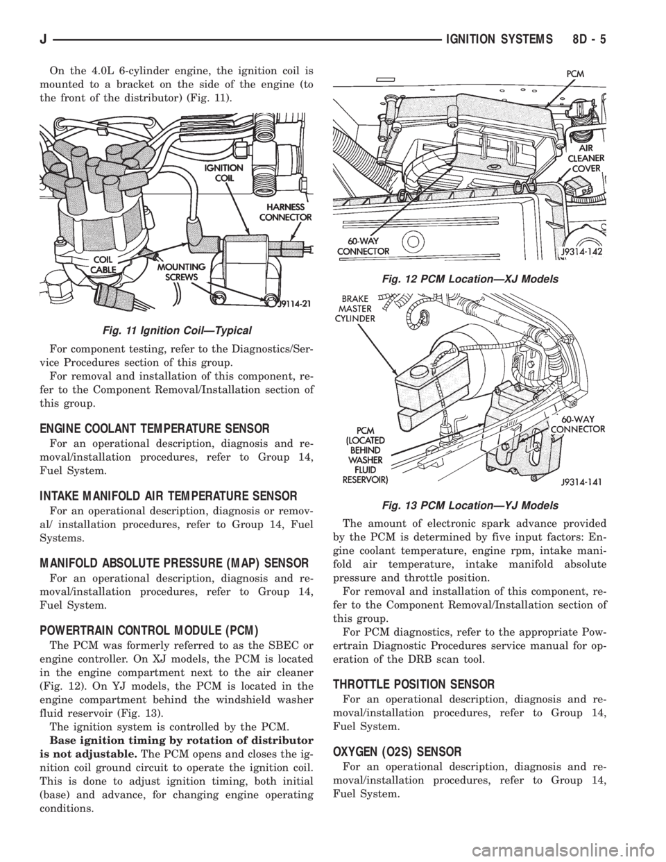
On the 4.0L 6-cylinder engine, the ignition coil is
mounted to a bracket on the side of the engine (to
the front of the distributor) (Fig. 11).
For component testing, refer to the Diagnostics/Ser-
vice Procedures section of this group.
For removal and installation of this component, re-
fer to the Component Removal/Installation section of
this group.
ENGINE COOLANT TEMPERATURE SENSOR
For an operational description, diagnosis and re-
moval/installation procedures, refer to Group 14,
Fuel System.
INTAKE MANIFOLD AIR TEMPERATURE SENSOR
For an operational description, diagnosis or remov-
al/ installation procedures, refer to Group 14, Fuel
Systems.
MANIFOLD ABSOLUTE PRESSURE (MAP) SENSOR
For an operational description, diagnosis and re-
moval/installation procedures, refer to Group 14,
Fuel System.
POWERTRAIN CONTROL MODULE (PCM)
The PCM was formerly referred to as the SBEC or
engine controller. On XJ models, the PCM is located
in the engine compartment next to the air cleaner
(Fig. 12). On YJ models, the PCM is located in the
engine compartment behind the windshield washer
fluid reservoir (Fig. 13).
The ignition system is controlled by the PCM.
Base ignition timing by rotation of distributor
is not adjustable.The PCM opens and closes the ig-
nition coil ground circuit to operate the ignition coil.
This is done to adjust ignition timing, both initial
(base) and advance, for changing engine operating
conditions.The amount of electronic spark advance provided
by the PCM is determined by five input factors: En-
gine coolant temperature, engine rpm, intake mani-
fold air temperature, intake manifold absolute
pressure and throttle position.
For removal and installation of this component, re-
fer to the Component Removal/Installation section of
this group.
For PCM diagnostics, refer to the appropriate Pow-
ertrain Diagnostic Procedures service manual for op-
eration of the DRB scan tool.
THROTTLE POSITION SENSOR
For an operational description, diagnosis and re-
moval/installation procedures, refer to Group 14,
Fuel System.
OXYGEN (O2S) SENSOR
For an operational description, diagnosis and re-
moval/installation procedures, refer to Group 14,
Fuel System.
Fig. 11 Ignition CoilÐTypical
Fig. 12 PCM LocationÐXJ Models
Fig. 13 PCM LocationÐYJ Models
JIGNITION SYSTEMS 8D - 5
Page 317 of 2198
DIAGNOSTICS/SERVICE PROCEDURES
INDEX
page page
Automatic Shutdown (ASD) Relay Test.......... 6
Camshaft Position Sensor Test................ 6
Crankshaft Position Sensor Test............... 7
Distributor Cap............................ 7
Distributor Rotor........................... 8
DRB Scan Tool............................ 8
Engine Coolant Temperature Sensor Test........ 9
General Information........................ 6
Ignition Coil.............................. 9
Ignition Secondary Circuit Diagnosis........... 10Ignition Timing............................ 11
Intake Manifold Air Temperature Sensor Test..... 11
Manifold Absolute Pressure (MAP) Sensor Test . . . 11
On-Board Diagnostics...................... 15
Oxygen (O2S) Sensor Tests................. 15
Powertrain Control Module (PCM)............. 11
Spark Plug Secondary Cables................ 14
Spark Plugs............................. 12
Throttle Position Sensor Test................. 15
GENERAL INFORMATION
This section of the group, Diagnostics/Service Pro-
cedures, will discuss basic ignition system diagnostics
and service adjustments.
For system operation and component identification,
refer to the Component Identification/System Opera-
tion section of this group.
For removal or installation of ignition system com-
ponents, refer to the Component Removal/Installa-
tion section of this group.
For other useful information, refer to the On-Board
Diagnostics section.
For operation of the DRB Scan Tool, refer to the
appropriate Powertrain Diagnostic Procedures ser-
vice manual.
AUTOMATIC SHUTDOWN (ASD) RELAY TEST
To perform a complete test of this relay and its cir-
cuitry, refer to the DRB scan tool. Also refer to the
appropriate Powertrain Diagnostics Procedures man-
ual. To test the relay only, refer to RelaysÐOpera-
tion/Testing in the Group 14, Fuel Systems section.
CAMSHAFT POSITION SENSOR TEST
To perform a complete test of this sensor and its
circuitry, refer to the DRB scan tool. Also refer to the
appropriate Powertrain Diagnostics Procedures man-
ual. To test the sensor only, refer to the following:
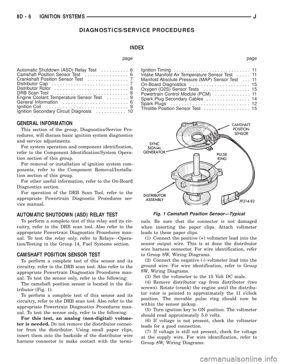
The camshaft position sensor is located in the dis-
tributor (Fig. 1).
To perform a complete test of this sensor and its
circuitry, refer to the DRB scan tool. Also refer to the
appropriate Powertrain Diagnostics Procedures man-
ual. To test the sensor only, refer to the following:
For this test, an analog (non-digital) voltme-
ter is needed.Do not remove the distributor connec-
tor from the distributor. Using small paper clips,
insert them into the backside of the distributor wire
harness connector to make contact with the termi-nals. Be sure that the connector is not damaged
when inserting the paper clips. Attach voltmeter
leads to these paper clips.
(1) Connect the positive (+) voltmeter lead into the
sensor output wire. This is at done the distributor
wire harness connector. For wire identification, refer
to Group 8W, Wiring Diagrams.
(2) Connect the negative (-) voltmeter lead into the
ground wire. For wire identification, refer to Group
8W, Wiring Diagrams.
(3) Set the voltmeter to the 15 Volt DC scale.
(4) Remove distributor cap from distributor (two
screws). Rotate (crank) the engine until the distribu-
tor rotor is pointed to approximately the 11 o'clock
position. The movable pulse ring should now be
within the sensor pickup.
(5) Turn ignition key to ON position. The voltmeter
should read approximately 5.0 volts.
(6) If voltage is not present, check the voltmeter
leads for a good connection.
(7) If voltage is still not present, check for voltage
at the supply wire. For wire identification, refer to
Group 8W, Wiring Diagrams.
Fig. 1 Camshaft Position SensorÐTypical
8D - 6 IGNITION SYSTEMSJ
Page 318 of 2198

(8) If voltage is not present at supply wire, check
for voltage at pin-7 of powertrain control module
(PCM) 60-way connector. Leave the PCM connector
connected for this test.
(9) If voltage is still not present, perform vehicle
test using the DRB scan tool.
(10) If voltage is present at pin-7, but not at the
supply wire:
(a) Check continuity between the supply wire.
This is checked between the distributor connector
and pin-7 at the PCM. If continuity is not present,
repair the harness as necessary.
(b) Check for continuity between the camshaft
position sensor output wire and pin-44 at the PCM.
If continuity is not present, repair the harness as
necessary.
(c) Check for continuity between the ground cir-
cuit wire at the distributor connector and ground.
If continuity is not present, repair the harness as
necessary.
(11) While observing the voltmeter, crank the en-
gine with ignition switch. The voltmeter needle
should fluctuate between 0 and 5 volts while the en-
gine is cranking. This verifies that the camshaft po-
sition sensor in the distributor is operating properly
and a sync pulse signal is being generated.
If sync pulse signal is not present, replacement of
the camshaft position sensor is necessary.
For removal or installation of ignition system com-
ponents, refer to the Component Removal/Installa-
tion section of this group.
For system operation and component identification,
refer to the Component Identification/System Opera-
tion section of this group.
CRANKSHAFT POSITION SENSOR TEST
To perform a complete test of this sensor and its
circuitry, refer to the DRB scan tool. Also refer to the
appropriate Powertrain Diagnostics Procedures man-
ual. To test the sensor only, refer to the following:
The sensor is located on the transmission bellhous-
ing at the left/rear side of the engine block (Figs. 2, 3
or 4).
(1) Near the rear of the intake manifold, discon-
nect sensor pigtail harness connector from main wir-
ing harness.
(2) Place an ohmmeter across terminals B and C
(Fig. 5). Ohmmeter should be set to 1K-to-10K scale
for this test. The meter reading should be open (no
resistance). Replace sensor if a low resistance is indi-
cated.
For removal or installation of ignition system com-
ponents, refer to the Component Removal/Installa-
tion section of this group.DISTRIBUTOR CAP
INSPECTION
Remove the distributor cap and wipe it clean with
a dry lint free cloth. Visually inspect the cap for
cracks, carbon paths, broken towers, or damaged ro-
tor button (Figs. 6 and 7). Also check for white depos-
its on the inside (caused by condensation entering
the cap through cracks). Replace any cap that dis-
plays charred or eroded terminals. The inside flat
surface of a terminal end (faces toward rotor) will in-
dicate some evidence of erosion from normal opera-
tion. Examine the terminal ends for evidence of
mechanical interference with the rotor tip.
If replacement of the distributor cap is necessary,
transfer spark plug cables from the original cap to
the new cap. This should be done one cable at a time.
Each cable is installed onto the tower of the new cap
that corresponds to its tower position on the original
Fig. 2 Crankshaft Position SensorÐ2.5L 4-Cyl.
EngineÐTypical
Fig. 3 Crankshaft Position SensorÐ4.0L 6-Cyl.
EngineÐAll Except YJ models With Auto. Trans.
JIGNITION SYSTEMS 8D - 7
Page 322 of 2198
(4) Crank the engine for 5 seconds while monitor-
ing the voltage at the coil positive terminal:
²If the voltage remains near zero during the entire
period of cranking, refer to On-Board Diagnostics in
Group 14, Fuel Systems. Check the powertrain con-
trol module (PCM) and auto shutdown relay.
²If voltage is at or near battery voltage and drops
to zero after 1-2 seconds of cranking, check the cam-
shaft position sensor-to-PCM circuit. Refer to On-
Board Diagnostics in Group 14, Fuel Systems.
²If voltage remains at or near battery voltage dur-
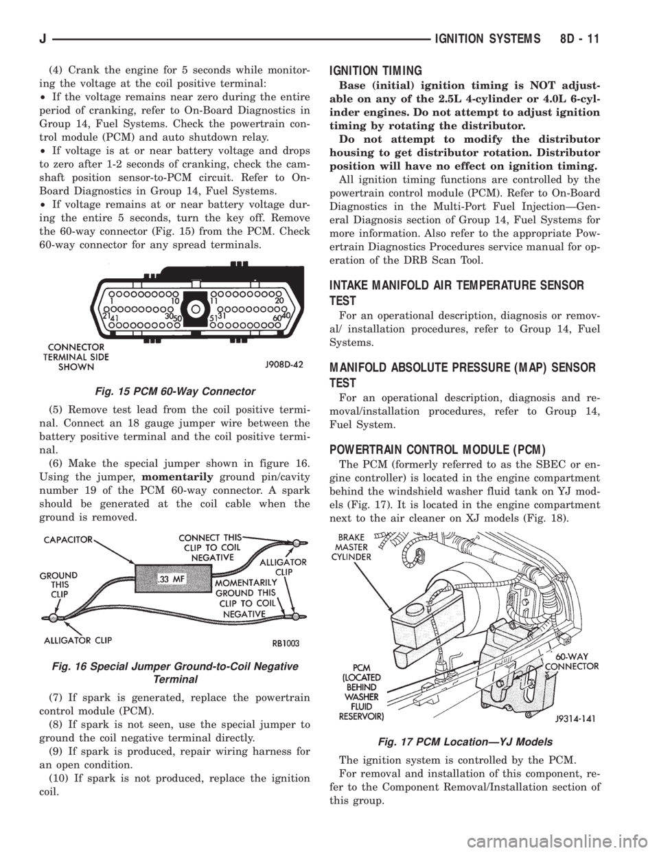
ing the entire 5 seconds, turn the key off. Remove
the 60-way connector (Fig. 15) from the PCM. Check
60-way connector for any spread terminals.
(5) Remove test lead from the coil positive termi-
nal. Connect an 18 gauge jumper wire between the
battery positive terminal and the coil positive termi-
nal.
(6) Make the special jumper shown in figure 16.
Using the jumper,momentarilyground pin/cavity
number 19 of the PCM 60-way connector. A spark
should be generated at the coil cable when the
ground is removed.
(7) If spark is generated, replace the powertrain
control module (PCM).
(8) If spark is not seen, use the special jumper to
ground the coil negative terminal directly.
(9) If spark is produced, repair wiring harness for
an open condition.
(10) If spark is not produced, replace the ignition
coil.IGNITION TIMING
Base (initial) ignition timing is NOT adjust-
able on any of the 2.5L 4-cylinder or 4.0L 6-cyl-
inder engines. Do not attempt to adjust ignition
timing by rotating the distributor.
Do not attempt to modify the distributor
housing to get distributor rotation. Distributor
position will have no effect on ignition timing.
All ignition timing functions are controlled by the
powertrain control module (PCM). Refer to On-Board
Diagnostics in the Multi-Port Fuel InjectionÐGen-
eral Diagnosis section of Group 14, Fuel Systems for
more information. Also refer to the appropriate Pow-
ertrain Diagnostics Procedures service manual for op-
eration of the DRB Scan Tool.
INTAKE MANIFOLD AIR TEMPERATURE SENSOR
TEST
For an operational description, diagnosis or remov-
al/ installation procedures, refer to Group 14, Fuel
Systems.
MANIFOLD ABSOLUTE PRESSURE (MAP) SENSOR
TEST
For an operational description, diagnosis and re-
moval/installation procedures, refer to Group 14,
Fuel System.
POWERTRAIN CONTROL MODULE (PCM)
The PCM (formerly referred to as the SBEC or en-
gine controller) is located in the engine compartment
behind the windshield washer fluid tank on YJ mod-
els (Fig. 17). It is located in the engine compartment
next to the air cleaner on XJ models (Fig. 18).
The ignition system is controlled by the PCM.
For removal and installation of this component, re-
fer to the Component Removal/Installation section of
this group.
Fig. 15 PCM 60-Way Connector
Fig. 16 Special Jumper Ground-to-Coil Negative
Terminal
Fig. 17 PCM LocationÐYJ Models
JIGNITION SYSTEMS 8D - 11
Page 326 of 2198
To test ignition coil-to-distributor cap cable, do not
remove the cable from the cap. Connect ohmmeter to
rotor button (center contact) of distributor cap and
terminal at ignition coil end of cable. If resistance is
not within specifications as found in the Spark Plug
Cable Resistance chart, remove the cable from the
distributor cap. Connect the ohmmeter to the termi-
nal ends of the cable. If resistance is not within spec-
ifications as found in the Spark Plug Cable
Resistance chart, replace the cable. Inspect the igni-
tion coil tower for cracks, burns or corrosion.
For removal and installation of spark plug cables,
refer to Spark Plug Secondary Cables in the Compo-
nent Removal/Installation section.
THROTTLE POSITION SENSOR TEST
For an operational description, diagnosis and re-
moval/installation procedures, refer to Group 14,
Fuel System.
OXYGEN (O2S) SENSOR TESTS
For an operational description, diagnosis or remov-
al/ installation procedures, refer to Group 14, Fuel
Systems.
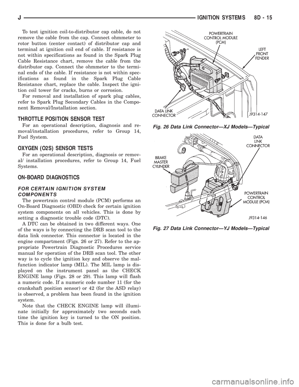
ON-BOARD DIAGNOSTICS
FOR CERTAIN IGNITION SYSTEM
COMPONENTS
The powertrain control module (PCM) performs an
On-Board Diagnostic (OBD) check for certain ignition
system components on all vehicles. This is done by
setting a diagnostic trouble code (DTC).
A DTC can be obtained in two different ways. One
of the ways is by connecting the DRB scan tool to the
data link connector. This connector is located in the
engine compartment (Figs. 26 or 27). Refer to the ap-
propriate Powertrain Diagnostic Procedures service
manual for operation of the DRB scan tool. The other
way is to cycle the ignition key and observe the mal-
function indicator lamp (MIL). The MIL lamp is dis-
played on the instrument panel as the CHECK
ENGINE lamp (Figs. 28 or 29). This lamp will flash
a numeric code. If a numeric code number 11 (for the
crankshaft position sensor) or 42 (for the ASD relay)
is observed, a problem has been found in the ignition
system.
Note that the CHECK ENGINE lamp will illumi-
nate initially for approximately two seconds each
time the ignition key is turned to the ON position.
This is done for a bulb test.
Fig. 26 Data Link ConnectorÐXJ ModelsÐTypical
Fig. 27 Data Link ConnectorÐYJ ModelsÐTypical
JIGNITION SYSTEMS 8D - 15