oil level JEEP CHEROKEE 1995 Service Repair Manual
[x] Cancel search | Manufacturer: JEEP, Model Year: 1995, Model line: CHEROKEE, Model: JEEP CHEROKEE 1995Pages: 2198, PDF Size: 82.83 MB
Page 5 of 2198
MAINTENANCE SCHEDULES
INTRODUCTION
There are two maintenance schedules that show
proper service intervals for Jeep Cherokee and Jeep
Wrangler vehicles. Use the schedule that best de-
scribes the conditions the vehicle is operated under.
When mileage and time is listed, follow the interval
that occurs first.
ScheduleÐAlists all the scheduled maintenance
to be performed under normal operating conditions.
ScheduleÐBis a schedule for vehicles that are
usually operated under one or more of the following
conditions.
²Frequent short trip driving less than 5 miles (8
km).
²Frequent driving in dusty conditions.
²Trailer towing or heavy load hauling.
²Frequent long periods of engine idling.
²Sustained high speed operation.
²Desert operation.
²Frequent starting and stopping.
²Cold climate operation.
²Off road driving.
²Commercial service.
²Snow plow operation.
²More than half of vehicle operation occurs in
heavy city traffic during hot weather (above 90É F).
AT EACH STOP FOR GASOLINE
²Check engine oil level and add as required.
²Check windshield washer solvent and add as re-
quired.
ONCE A MONTH
²Check tire pressure and look for unusual tire wear
or damage.
²Check fluid levels of coolant reservoir, brake mas-
ter cylinder, power steering and transmission. Add
fluid as required.
²Check all lights and other electrical items for cor-
rect operation.
²Inspect battery and clean and tighten terminals as
required.
²Check rubber seals on each side of the radiator for
proper fit.
AT EACH OIL CHANGE
²Inspect exhaust system.
²Inspect brake hoses.
²Rotate the tires at each oil change interval shown
on ScheduleÐA: (7,500 Miles) or every other interval
shown on ScheduleÐB: (6,000 Miles).
²Check engine coolant level, hoses, and clamps.
²Lubricate 4x4 steering linkage.
²Lubricate propeller shaft universal joints and slip
spline, if equipped.After completion of off-road (4WD) operation, the
underside of the vehicle should be thoroughly in-
spected. Examine threaded fasteners for looseness.
HARSH SURFACE ENVIRONMENTS
After vehicle operation in a harsh surface environ-
ment, the following components should be inspected
and cleaned as soon as possible:
²Brake drums.
²Brake linings.
²Front wheel bearings (2WD vehicles only).
²Axle coupling joints.
This will prevent wear and/or unpredictable brake
action.
EMISSION CONTROL SYSTEM MAINTENANCE
The schedule emission maintenance listed inbold
typeon the following schedules, must be done at the
mileage specified to assure the continued proper
functioning of the emission control system. These,
and all other maintenance services included in this
manual, should be done to provide the best vehicle
performance and reliability. More frequent mainte-
nance may be needed for vehicles in severe operating
conditions such as dusty areas and very short trip
driving.
SCHEDULEÐA
7,500 MILES (12 000 KM) OR AT 6 MONTHS
²Change engine oil.
²Replace engine oil filter.
²Lubricate steering linkage (4x4).
15,000 MILES (24 000 KM) OR AT 12 MONTHS
²Change engine oil.
²Replace engine oil filter.
²Lubricate steering linkage.
22,500 MILES (36 000 KM) OR AT 18 MONTHS
²Change engine oil.
²Replace engine oil filter.
²Lubricate steering linkage (4x4).
²Inspect brake linings.
30,000 MILES (48 000 KM) OR AT 24 MONTHS
²Replace air cleaner element.
²Replace spark plugs.
²Adjust belt tension on non-automatic tensioning
drive belts.
²Change engine oil.
²Replace engine oil filter.
²Lubricate steering linkage.
²Drain and refill automatic transmission.
²Drain and refill transfer case.
0 - 4 LUBRICATION AND MAINTENANCEJ
Page 17 of 2198
CONTAINER IDENTIFICATION
Standard engine oil identification notations have
been adopted to aid in the proper selection of engine
oil. The identifying notations are located on the label
of engine oil plastic bottles and the top of engine oil
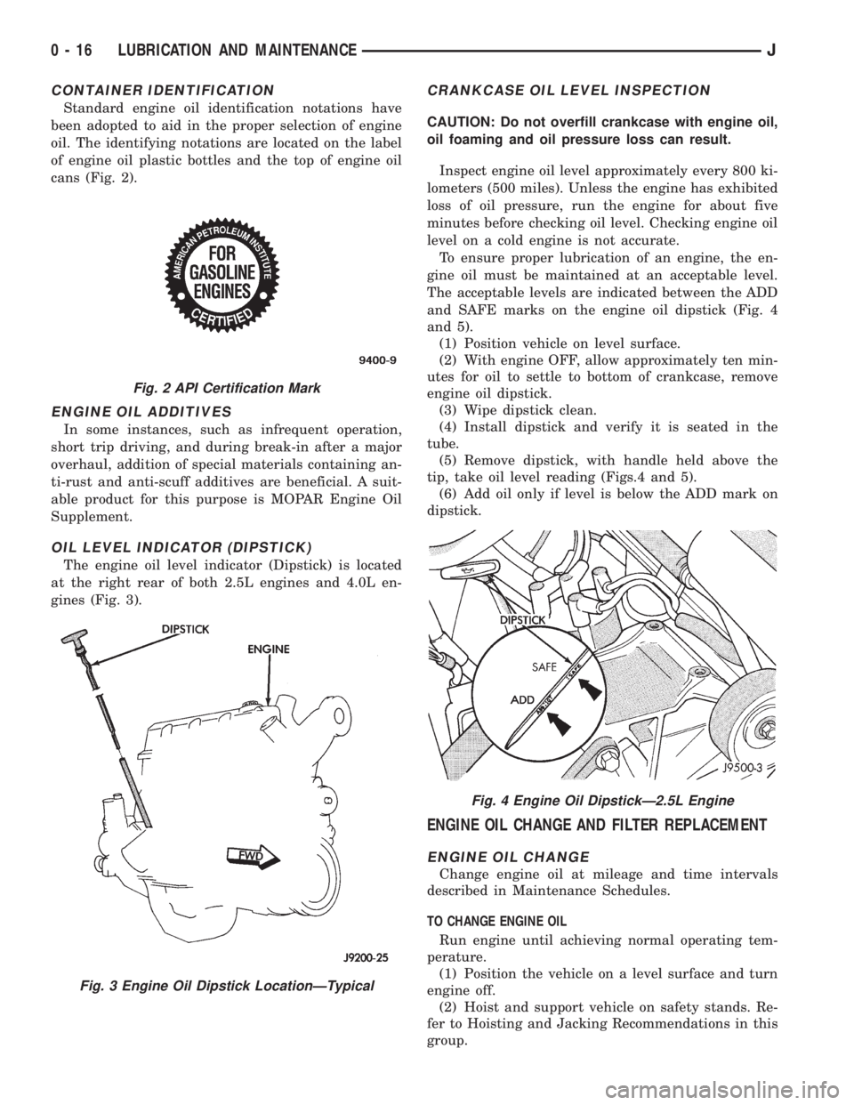
cans (Fig. 2).
ENGINE OIL ADDITIVES
In some instances, such as infrequent operation,
short trip driving, and during break-in after a major
overhaul, addition of special materials containing an-
ti-rust and anti-scuff additives are beneficial. A suit-
able product for this purpose is MOPAR Engine Oil
Supplement.
OIL LEVEL INDICATOR (DIPSTICK)
The engine oil level indicator (Dipstick) is located
at the right rear of both 2.5L engines and 4.0L en-
gines (Fig. 3).
CRANKCASE OIL LEVEL INSPECTION
CAUTION: Do not overfill crankcase with engine oil,
oil foaming and oil pressure loss can result.
Inspect engine oil level approximately every 800 ki-
lometers (500 miles). Unless the engine has exhibited
loss of oil pressure, run the engine for about five
minutes before checking oil level. Checking engine oil
level on a cold engine is not accurate.
To ensure proper lubrication of an engine, the en-
gine oil must be maintained at an acceptable level.
The acceptable levels are indicated between the ADD
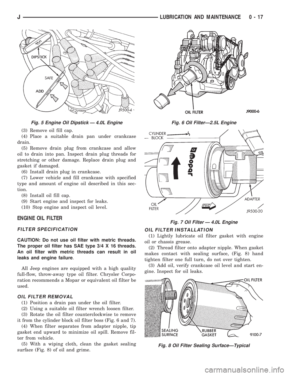
and SAFE marks on the engine oil dipstick (Fig. 4
and 5).
(1) Position vehicle on level surface.
(2) With engine OFF, allow approximately ten min-
utes for oil to settle to bottom of crankcase, remove
engine oil dipstick.
(3) Wipe dipstick clean.
(4) Install dipstick and verify it is seated in the
tube.
(5) Remove dipstick, with handle held above the
tip, take oil level reading (Figs.4 and 5).
(6) Add oil only if level is below the ADD mark on
dipstick.
ENGINE OIL CHANGE AND FILTER REPLACEMENT
ENGINE OIL CHANGE
Change engine oil at mileage and time intervals
described in Maintenance Schedules.
TO CHANGE ENGINE OIL
Run engine until achieving normal operating tem-
perature.
(1) Position the vehicle on a level surface and turn
engine off.
(2) Hoist and support vehicle on safety stands. Re-
fer to Hoisting and Jacking Recommendations in this
group.
Fig. 2 API Certification Mark
Fig. 3 Engine Oil Dipstick LocationÐTypical
Fig. 4 Engine Oil DipstickÐ2.5L Engine
0 - 16 LUBRICATION AND MAINTENANCEJ
Page 18 of 2198
(3) Remove oil fill cap.
(4) Place a suitable drain pan under crankcase
drain.
(5) Remove drain plug from crankcase and allow
oil to drain into pan. Inspect drain plug threads for
stretching or other damage. Replace drain plug and
gasket if damaged.
(6) Install drain plug in crankcase.
(7) Lower vehicle and fill crankcase with specified
type and amount of engine oil described in this sec-
tion.
(8) Install oil fill cap.
(9) Start engine and inspect for leaks.
(10) Stop engine and inspect oil level.
ENGINE OIL FILTER
FILTER SPECIFICATION
CAUTION: Do not use oil filter with metric threads.
The proper oil filter has SAE type 3/4 X 16 threads.
An oil filter with metric threads can result in oil
leaks and engine failure.
All Jeep engines are equipped with a high quality
full-flow, throw-away type oil filter. Chrysler Corpo-
ration recommends a Mopar or equivalent oil filter be
used.
OIL FILTER REMOVAL
(1) Position a drain pan under the oil filter.
(2) Using a suitable oil filter wrench loosen filter.
(3) Rotate the oil filter counterclockwise to remove
it from the cylinder block oil filter boss (Fig. 6 and 7).
(4) When filter separates from adapter nipple, tip
gasket end upward to minimize oil spill. Remove fil-
ter from vehicle.
(5) With a wiping cloth, clean the gasket sealing
surface (Fig. 8) of oil and grime.
OIL FILTER INSTALLATION
(1) Lightly lubricate oil filter gasket with engine
oil or chassis grease.
(2) Thread filter onto adapter nipple. When gasket
makes contact with sealing surface, (Fig. 8) hand
tighten filter one full turn, do not over tighten.
(3) Add oil, verify crankcase oil level and start en-
gine. Inspect for oil leaks.
Fig. 5 Engine Oil Dipstick Ð 4.0L EngineFig. 6 Oil FilterÐ2.5L Engine
Fig. 7 Oil Filter Ð 4.0L Engine
Fig. 8 Oil Filter Sealing SurfaceÐTypical
JLUBRICATION AND MAINTENANCE 0 - 17
Page 19 of 2198
USED ENGINE OIL DISPOSAL
Care should be exercised when disposing used en-
gine oil after it has been drained from a vehicle en-
gine. Refer to the WARNING listed above.
ENGINE COOLING SYSTEM
WARNINGS AND PRECAUTIONS
WARNING: ANTIFREEZE IS AN ETHYLENE GLYCOL
BASE COOLANT AND IS HARMFUL IF SWAL-
LOWED OR INHALED. IF SWALLOWED, DRINK
TWO GLASSES OF WATER AND INDUCE VOMIT-
ING. IF INHALED, MOVE TO FRESH AIR AREA.
SEEK MEDICAL ATTENTION IMMEDIATELY. DO NOT
STORE IN OPEN OR UNMARKED CONTAINERS.
WASH SKIN AND CLOTHING THOROUGHLY AFTER
COMING IN CONTACT WITH ETHYLENE GLYCOL.
KEEP OUT OF REACH OF CHILDREN.
DISPOSE OF GLYCOL BASE COOLANT PROP-
ERLY, CONTACT YOUR DEALER OR GOVERNMENT
AGENCY FOR LOCATION OF COLLECTION CENTER
IN YOUR AREA.
DO NOT OPEN A COOLING SYSTEM WHEN THE
ENGINE IS AT RUNNING TEMPERATURE, PER-
SONAL INJURY CAN RESULT.
AVOID RADIATOR COOLING FAN WHEN ENGINE
COMPARTMENT RELATED SERVICE IS PER-
FORMED, PERSONAL INJURY CAN RESULT.
CAUTION: Do not use straight antifreeze as engine
coolant, inadequate engine running temperatures
can result.
Do not operate vehicle without proper concentra-
tion of recommended ethylene glycol coolant, high
running temperatures and cooling system corrosion
can result.
The engine cooling system will develop internal
pressure of 97 to 123 kPa (14 to 18 psi) at normal op-
erating temperature. Allow the vehicle approximately
one half hour to cool off before opening the cooling
system. As an indicator of pressure, squeeze the up-
per radiator hose between index finger and thumb. If
it collapses with little effort the system would have
low internal pressure and should be safe to open to
the first safety notch of the radiator cap. Refer to
Group 7, Cooling System.
COOLING SYSTEM INSPECTION
Coolant level should be inspected when other en-
gine compartment service is performed or when cool-
ant leak is suspected. With the engine at normal
operating temperature, observe the coolant level in
thecoolant recovery bottle. The coolant level mustbe at least above the ADD mark and preferably at
the FULL mark. Add coolant to the coolant recovery
bottleonly, if necessary.
Cooling system freeze protection should be tested
at the onset of the winter season or every 12 months.
Service is required if coolant is low, contaminated,
rusty or freeze protection is inadequate. To properly
test cooling system, see Group 7, Cooling System.
The cooling system factory fill is a mixture of 50%
Ethylene Glycol based antifreeze and 50% water. Us-
ing a suitable hydrometer, measure antifreeze con-
centration in the radiator when the engine is cool. If
the cooling system has recently been serviced, allow
coolant to circulate for at least 20 minutes before
taking hydrometer reading. Properly mixed coolant
will protect the cooling system to -37ÉC (-35ÉF). If the
freeze protection is above -28ÉC (-20ÉF), drain enough
coolant from the cooling system to allow room to add
antifreeze to achieve adequate protection. A mix table
on the coolant container indicates the amount of an-
tifreeze required to winterize the cooling system
based on the capacity, see Capacity Chart in General
Information section of this group.
ANTIFREEZE SPECIFICATION
Chrysler Corporation recommends the use of Mo-
par Antifreeze/Coolant or a high quality, ethylene
glycol base antifreeze/coolant, with a silicate inhibi-
tor.
COOLING SYSTEM SERVICE
The cooling system should be drained, flushed and
filled with the proper coolant mixture at the inter-
vals described in the Lubrication and Maintenance
Schedules. Refer to General Information section of
this group. For proper service instructions see Group
7, Cooling System.
AIR CLEANER ELEMENT
The air cleaner element should be serviced at the
intervals described in the Lubrication and Mainte-
nance Schedules sections of this group. Additional in-
formation can be found in Group 14, Fuel System
and Group 25, Emission System. Inspect all air
cleaner hoses or tubes for damage or leaks when
other engine compartment service is performed. Re-
place faulty components.
FILTER ELEMENT SERVICE/REPLACEMENT
CAUTION: The air cleaner cover must be installed
properly for the emissions system and engine con-
troller to function correctly.
Do not immerse paper air filter element in clean-
ing solvents, damage can result.
(1) Remove the air cleaner cover from the body/
housing (Fig. 9).
0 - 18 LUBRICATION AND MAINTENANCEJ
Page 21 of 2198
line. You may encounter fuels containing 3 percent or
more methanol along with other alcohols called cosol-
vents.
Problems that are the result of using methanol/gas-
oline blends are not the responsibility of Chrysler
Corporation. They may not be covered by the vehicle
warranty.
MTBE/ETBE
Gasoline and MTBE (Methyl Tertiary Butyl Ether)
blends are a mixture of unleaded gasoline and up to
15 percent MTBE. Gasoline and ETBE (Ethyl Ter-
tiary Butyl Ether) are blends of gasoline and up to
17 percent ETBE. Gasoline blended with MTBE or
ETBE may be used.
CLEAN AIR GASOLINE
Many gasolines are now being blended that con-
tribute to cleaner air, especially in those areas of the
country where air pollution levels are high. These
new blends provide a cleaner burning fuel and some
are referred to asReformulated Gasoline.
In areas of the country where carbon monoxide lev-
els are high, gasolines are being treated with oxygen-
ated materials such as MTBE, ETBE and ethanol.
Chrysler Corporation supports these efforts toward
cleaner air and recommends the use of these gaso-
lines as they become available.
IGNITION CABLES, DISTRIBUTOR CAP AND
ROTOR
Inspect and test ignition cables, distributor cap and
rotor when the spark plugs are replaced. Oil and
grime should be cleaned from the ignition cables and
distributor cap to avoid possible spark plug fouling.
Mopar Foamy Engine Degreaser or equivalent is rec-
ommended for cleaning the engine compartment. For
proper service and diagnostic procedures refer to
Group 8D, Ignition System.
IGNITION TIMING
The ignition timing for 2.5L and 4.0L engines is
not adjustable. Refer to the specifications listed on
the engine Emission Control Information Label. Re-
fer to Group 25, Emission Control Systems for addi-
tional information.
SPARK PLUGS
Ignition spark plugs should be replaced at the
mileage interval described in the Lubrication and
Maintenance Schedules. Refer to the General Infor-
mation section of this group. For proper service pro-
cedures refer to Group 8D, Ignition Systems.
BATTERY
WARNING: WEAR SAFETY GLASSES, RUBBER
GLOVES AND PROTECTIVE CLOTHING WHEN HAN-DLING/SERVICING A BATTERY. THE BATTERY
ELECTROLYTE CONTAINS SULFURIC ACID AND
WILL CAUSE HARM IF IT CONTACTS SKIN, EYES
OR CLOTHING. IT WILL ALSO DAMAGE PAINTED
(AS WELL AS UN-PAINTED) SURFACES OF A VEHI-
CLE. IF SULFURIC ACID CONTACTS ANY OF
THESE, FLUSH IMMEDIATELY WITH LARGE
AMOUNTS OF WATER. IF SULFURIC ACID CON-
TACTS SKIN OR EYES, GET IMMEDIATE MEDICAL
ATTENTION. DO NOT SMOKE IN THE VICINITY OF A
BATTERY. KEEP OPEN FLAMES AND SPARKS
AWAY FROM BATTERY FILLER CAPS BECAUSE
EXPLOSIVE GAS IS ALWAYS PRESENT.
Inspect battery tray, hold down and terminal con-
nections when other under hood service is performed.
For proper diagnostic procedures refer to Group 8A,
Battery/Starting/Charging System Diagnostics. For
service and cleaning procedures refer to Group 8B,
Battery/Starter Service.
Care should be taken when disposing a bat-
tery after removal from a vehicle. Lead-acid
batteries are highly poisonous and, when indis-
criminately disposed, could create a problem
for the environment. Contact the applicable lo-
cal city or county government agency to deter-
mine where automobile (lead-acid) batteries
can be properly disposed in the local area.
RUBBER AND PLASTIC COMPONENT INSPECTION
CAUTION: Plastic hoses or wire harness covers will
melt or deform when exposed to heat from exhaust
system or engine manifolds.
Position plastic or rubber components away from
moving parts in engine compartment or under vehi-
cle, or damage will result.
Do not allow rubber engine mounts or other com-
ponents to become oil contaminated, repair cause
of oil contamination and clean area.
All rubber and plastic components should be in-
spected when engine compartment or under vehicle
service is performed. When evidence of deterioration
exists, replacement is required. To reduce deteriora-
tion of rubber components, Chrysler Corporation rec-
ommends Mopar Foamy Engine Degreaser or
equivalent be used to clean engine compartment of
oil and road grime.
EMISSION CONTROL SYSTEM
Inspect all emission control components and hoses
when other under hood service is performed. Refer to
emission system Vacuum Hose Label located on the
inside of the hood in the engine compartment and
Group 25, Emission Control Systems for proper ser-
vice procedures.
0 - 20 LUBRICATION AND MAINTENANCEJ
Page 22 of 2198
ENGINE SUPPORTS
The general condition of the engine supports
should be inspected when engine compartment or un-
der vehicle service is performed.
INSPECTION
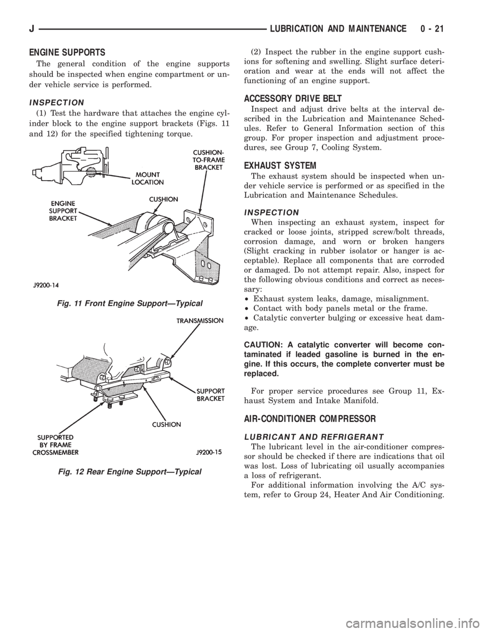
(1) Test the hardware that attaches the engine cyl-
inder block to the engine support brackets (Figs. 11
and 12) for the specified tightening torque.(2) Inspect the rubber in the engine support cush-
ions for softening and swelling. Slight surface deteri-
oration and wear at the ends will not affect the
functioning of an engine support.
ACCESSORY DRIVE BELT
Inspect and adjust drive belts at the interval de-
scribed in the Lubrication and Maintenance Sched-
ules. Refer to General Information section of this
group. For proper inspection and adjustment proce-
dures, see Group 7, Cooling System.
EXHAUST SYSTEM
The exhaust system should be inspected when un-
der vehicle service is performed or as specified in the
Lubrication and Maintenance Schedules.
INSPECTION
When inspecting an exhaust system, inspect for
cracked or loose joints, stripped screw/bolt threads,
corrosion damage, and worn or broken hangers
(Slight cracking in rubber isolator or hanger is ac-
ceptable). Replace all components that are corroded
or damaged. Do not attempt repair. Also, inspect for
the following obvious conditions and correct as neces-
sary:
²Exhaust system leaks, damage, misalignment.
²Contact with body panels metal or the frame.
²Catalytic converter bulging or excessive heat dam-
age.
CAUTION: A catalytic converter will become con-
taminated if leaded gasoline is burned in the en-
gine. If this occurs, the complete converter must be
replaced.
For proper service procedures see Group 11, Ex-
haust System and Intake Manifold.
AIR-CONDITIONER COMPRESSOR
LUBRICANT AND REFRIGERANT
The lubricant level in the air-conditioner compres-
sor should be checked if there are indications that oil
was lost. Loss of lubricating oil usually accompanies
a loss of refrigerant.
For additional information involving the A/C sys-
tem, refer to Group 24, Heater And Air Conditioning.
Fig. 11 Front Engine SupportÐTypical
Fig. 12 Rear Engine SupportÐTypical
JLUBRICATION AND MAINTENANCE 0 - 21
Page 23 of 2198
DRIVETRAIN
INDEX
page page
Automatic Transmission.................... 23
Clutch and Brake Pedal Bushings............. 22
Clutch Master Cylinder..................... 22
Drive Shafts............................. 26Front and Rear Axles...................... 24
Manual Transmission...................... 22
Rubber and Plastic Hoses/Tubing............. 26
Transfer Case (4WD Vehicles)................ 24
CLUTCH AND BRAKE PEDAL BUSHINGS
If the clutch and brake pedal mechanism squeaks,
the pivot bushings should be lubricated. Use Mopar
Multi-Purpose Lubricant, or an equivalent. Refer to
Group 5, Brakes for location of bushings.
CLUTCH MASTER CYLINDER
LEVEL INSPECTION
WARNING: DO NOT ALLOW PETROLEUM OR WA-
TER BASE LIQUIDS TO CONTAMINATE CLUTCH
FLUID, SEAL DAMAGE AND CLUTCH FAILURE CAN
RESULT.
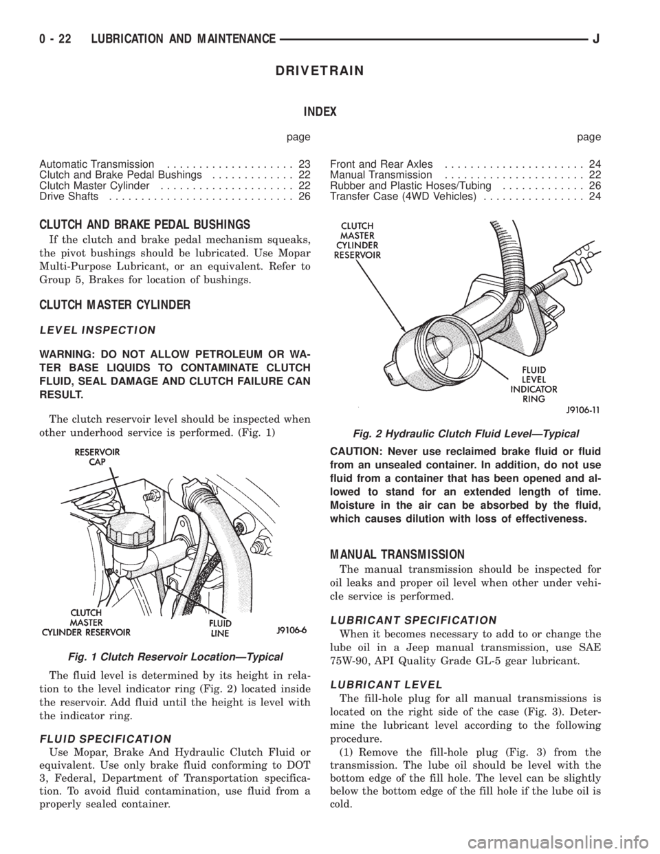
The clutch reservoir level should be inspected when
other underhood service is performed. (Fig. 1)
The fluid level is determined by its height in rela-
tion to the level indicator ring (Fig. 2) located inside
the reservoir. Add fluid until the height is level with
the indicator ring.
FLUID SPECIFICATION
Use Mopar, Brake And Hydraulic Clutch Fluid or
equivalent. Use only brake fluid conforming to DOT
3, Federal, Department of Transportation specifica-
tion. To avoid fluid contamination, use fluid from a
properly sealed container.CAUTION: Never use reclaimed brake fluid or fluid
from an unsealed container. In addition, do not use
fluid from a container that has been opened and al-
lowed to stand for an extended length of time.
Moisture in the air can be absorbed by the fluid,
which causes dilution with loss of effectiveness.
MANUAL TRANSMISSION
The manual transmission should be inspected for
oil leaks and proper oil level when other under vehi-
cle service is performed.
LUBRICANT SPECIFICATION
When it becomes necessary to add to or change the
lube oil in a Jeep manual transmission, use SAE
75W-90, API Quality Grade GL-5 gear lubricant.
LUBRICANT LEVEL
The fill-hole plug for all manual transmissions is
located on the right side of the case (Fig. 3). Deter-
mine the lubricant level according to the following
procedure.
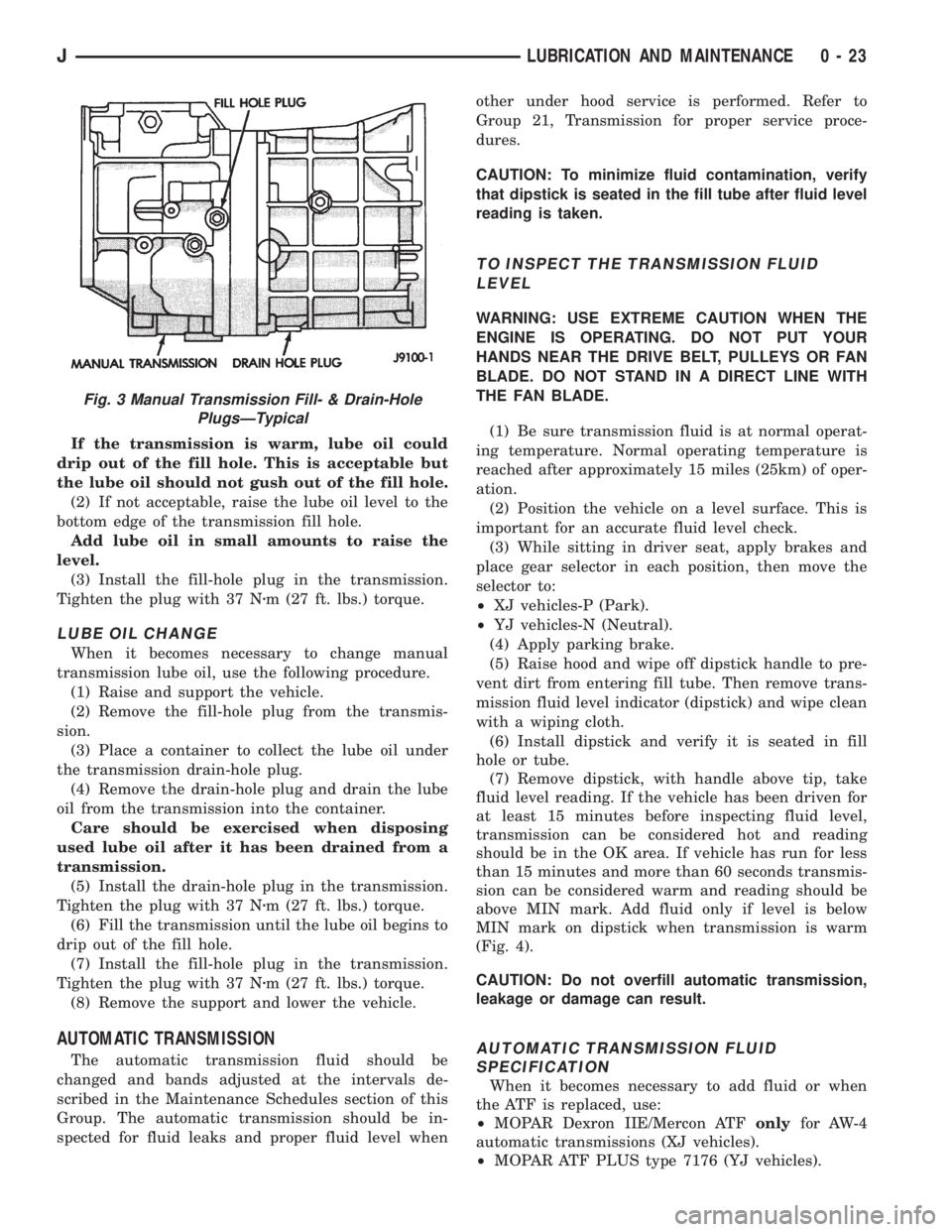
(1) Remove the fill-hole plug (Fig. 3) from the
transmission. The lube oil should be level with the
bottom edge of the fill hole. The level can be slightly
below the bottom edge of the fill hole if the lube oil is
cold.
Fig. 1 Clutch Reservoir LocationÐTypical
Fig. 2 Hydraulic Clutch Fluid LevelÐTypical
0 - 22 LUBRICATION AND MAINTENANCEJ
Page 24 of 2198
If the transmission is warm, lube oil could
drip out of the fill hole. This is acceptable but
the lube oil should not gush out of the fill hole.
(2) If not acceptable, raise the lube oil level to the
bottom edge of the transmission fill hole.
Add lube oil in small amounts to raise the
level.
(3) Install the fill-hole plug in the transmission.
Tighten the plug with 37 Nzm (27 ft. lbs.) torque.
LUBE OIL CHANGE
When it becomes necessary to change manual
transmission lube oil, use the following procedure.
(1) Raise and support the vehicle.
(2) Remove the fill-hole plug from the transmis-
sion.
(3) Place a container to collect the lube oil under
the transmission drain-hole plug.
(4) Remove the drain-hole plug and drain the lube
oil from the transmission into the container.
Care should be exercised when disposing
used lube oil after it has been drained from a
transmission.
(5) Install the drain-hole plug in the transmission.
Tighten the plug with 37 Nzm (27 ft. lbs.) torque.
(6) Fill the transmission until the lube oil begins to
drip out of the fill hole.
(7) Install the fill-hole plug in the transmission.
Tighten the plug with 37 Nzm (27 ft. lbs.) torque.
(8) Remove the support and lower the vehicle.
AUTOMATIC TRANSMISSION
The automatic transmission fluid should be
changed and bands adjusted at the intervals de-
scribed in the Maintenance Schedules section of this
Group. The automatic transmission should be in-
spected for fluid leaks and proper fluid level whenother under hood service is performed. Refer to
Group 21, Transmission for proper service proce-
dures.
CAUTION: To minimize fluid contamination, verify
that dipstick is seated in the fill tube after fluid level
reading is taken.
TO INSPECT THE TRANSMISSION FLUID
LEVEL
WARNING: USE EXTREME CAUTION WHEN THE
ENGINE IS OPERATING. DO NOT PUT YOUR
HANDS NEAR THE DRIVE BELT, PULLEYS OR FAN
BLADE. DO NOT STAND IN A DIRECT LINE WITH
THE FAN BLADE.
(1) Be sure transmission fluid is at normal operat-
ing temperature. Normal operating temperature is
reached after approximately 15 miles (25km) of oper-
ation.
(2) Position the vehicle on a level surface. This is
important for an accurate fluid level check.
(3) While sitting in driver seat, apply brakes and
place gear selector in each position, then move the
selector to:
²XJ vehicles-P (Park).
²YJ vehicles-N (Neutral).
(4) Apply parking brake.
(5) Raise hood and wipe off dipstick handle to pre-
vent dirt from entering fill tube. Then remove trans-
mission fluid level indicator (dipstick) and wipe clean
with a wiping cloth.
(6) Install dipstick and verify it is seated in fill
hole or tube.
(7) Remove dipstick, with handle above tip, take
fluid level reading. If the vehicle has been driven for
at least 15 minutes before inspecting fluid level,
transmission can be considered hot and reading
should be in the OK area. If vehicle has run for less
than 15 minutes and more than 60 seconds transmis-
sion can be considered warm and reading should be
above MIN mark. Add fluid only if level is below
MIN mark on dipstick when transmission is warm
(Fig. 4).
CAUTION: Do not overfill automatic transmission,
leakage or damage can result.
AUTOMATIC TRANSMISSION FLUID
SPECIFICATION
When it becomes necessary to add fluid or when
the ATF is replaced, use:
²MOPAR Dexron IIE/Mercon ATFonlyfor AW-4
automatic transmissions (XJ vehicles).
²MOPAR ATF PLUS type 7176 (YJ vehicles).
Fig. 3 Manual Transmission Fill- & Drain-Hole
PlugsÐTypical
JLUBRICATION AND MAINTENANCE 0 - 23
Page 26 of 2198
LUBRICANT LEVEL
Determine the axle differential housing lubricant
level according to the following procedure.
(1) Raise and support the vehicle.
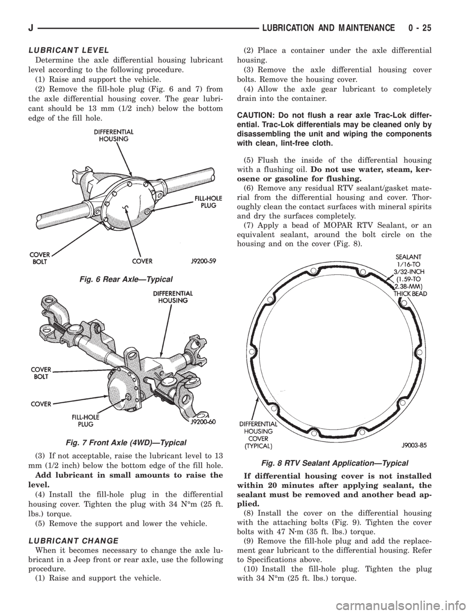
(2) Remove the fill-hole plug (Fig. 6 and 7) from
the axle differential housing cover. The gear lubri-
cant should be 13 mm (1/2 inch) below the bottom
edge of the fill hole.
(3) If not acceptable, raise the lubricant level to 13
mm (1/2 inch) below the bottom edge of the fill hole.
Add lubricant in small amounts to raise the
level.
(4) Install the fill-hole plug in the differential
housing cover. Tighten the plug with 34 NÉm (25 ft.
lbs.) torque.
(5) Remove the support and lower the vehicle.
LUBRICANT CHANGE
When it becomes necessary to change the axle lu-
bricant in a Jeep front or rear axle, use the following
procedure.
(1) Raise and support the vehicle.(2) Place a container under the axle differential
housing.
(3) Remove the axle differential housing cover
bolts. Remove the housing cover.
(4) Allow the axle gear lubricant to completely
drain into the container.
CAUTION: Do not flush a rear axle Trac-Lok differ-
ential. Trac-Lok differentials may be cleaned only by
disassembling the unit and wiping the components
with clean, lint-free cloth.
(5) Flush the inside of the differential housing
with a flushing oil.Do not use water, steam, ker-
osene or gasoline for flushing.
(6) Remove any residual RTV sealant/gasket mate-
rial from the differential housing and cover. Thor-
oughly clean the contact surfaces with mineral spirits
and dry the surfaces completely.
(7) Apply a bead of MOPAR RTV Sealant, or an
equivalent sealant, around the bolt circle on the
housing and on the cover (Fig. 8).
If differential housing cover is not installed
within 20 minutes after applying sealant, the
sealant must be removed and another bead ap-
plied.
(8) Install the cover on the differential housing
with the attaching bolts (Fig. 9). Tighten the cover
bolts with 47 Nzm (35 ft. lbs.) torque.
(9) Remove the fill-hole plug and add the replace-
ment gear lubricant to the differential housing. Refer
to Specifications above.
(10) Install the fill-hole plug. Tighten the plug
with 34 NÉm (25 ft. lbs.) torque.
Fig. 6 Rear AxleÐTypical
Fig. 7 Front Axle (4WD)ÐTypical
Fig. 8 RTV Sealant ApplicationÐTypical
JLUBRICATION AND MAINTENANCE 0 - 25
Page 29 of 2198
CHASSIS AND BODY COMPONENTS
INDEX
page page
Body Components........................ 32
Chassis Component and Wheel Bearing
Lubricants............................. 28
Front Wheel Bearings...................... 28
Headlamps.............................. 33
Manual Steering Gear...................... 30Power Brake System....................... 30
Power Steering System..................... 29
Speedometer Cable....................... 33
Steering Linkage.......................... 28
Tires................................... 32
CHASSIS COMPONENT AND WHEEL BEARING
LUBRICANTS
The chassis component and wheel bearing lubri-
cants that are recommended for Jeep vehicles are
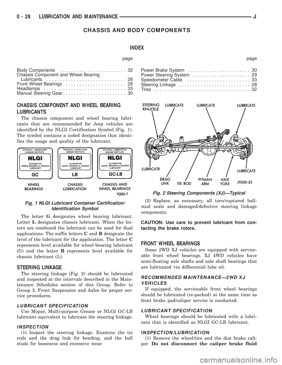
identified by the NLGI Certification Symbol (Fig. 1).
The symbol contains a coded designation that identi-
fies the usage and quality of the lubricant.
The letterGdesignates wheel bearing lubricant.
LetterLdesignates chassis lubricant. When the let-
ters are combined the lubricant can be used for dual
applications. The suffix lettersCandBdesignate the
level of the lubricant for the application. The letterC
represents level available for wheel bearing lubricant
(G) and the letterBrepresents level available for
chassis lubricant (L).
STEERING LINKAGE
The steering linkage (Fig. 2) should be lubricated
and inspected at the intervals described in the Main-
tenance Schedules section of this Group. Refer to
Group 2, Front Suspension and Axles for proper ser-
vice procedures.
LUBRICANT SPECIFICATION
Use Mopar, Multi-purpose Grease or NLGI GC-LB
lubricant equivalent to lubricate the steering linkage.
INSPECTION
(1) Inspect the steering linkage. Examine the tie
rods and the drag link for bending, and the ball
studs for looseness and excessive wear.(2) Replace, as necessary, all torn/ruptured ball-
stud seals and damaged/defective steering linkage
components.
CAUTION: Use care to prevent lubricant from con-
tacting the brake rotors.
FRONT WHEEL BEARINGS
Some 2WD XJ vehicles are equipped with service-
able front wheel bearings. XJ 4WD vehicles have
semi-floating axle shafts and axle shaft bearings that
are lubricated via differential lube oil.
RECOMMENDED MAINTENANCEÐ2WD XJ
VEHICLES
If equipped, the serviceable front wheel bearings
should be lubricated (re-packed) at the same time as
front brake pad/caliper service is conducted.
LUBRICANT SPECIFICATION
Wheel bearings should be lubricated with a lubri-
cant that is identified as NLGI GC-LB lubricant.
INSPECTION/LUBRICATION
(1) Remove the wheel/tire and the disc brake cali-
per.Do not disconnect the caliper brake fluid
Fig. 1 NLGI Lubricant Container Certification/
Identification Symbol
Fig. 2 Steering Components (XJ)ÐTypical
0 - 28 LUBRICATION AND MAINTENANCEJ