open hood JEEP CHEROKEE 1995 Service Repair Manual
[x] Cancel search | Manufacturer: JEEP, Model Year: 1995, Model line: CHEROKEE, Model: JEEP CHEROKEE 1995Pages: 2198, PDF Size: 82.83 MB
Page 10 of 2198
JUMP STARTING, TOWING AND HOISTING
INDEX
page page
Four-Wheel-Drive Vehicle Towing............. 12
Ground Clearance and Ramp Angle............ 11
Hoisting Recommendations.................. 10
Jump Starting Procedure..................... 9Towing Recommendations................... 10
Towing When Keys Are Not Available.......... 13
Two-Wheel-Drive Vehicle TowingÐXJ.......... 11
JUMP STARTING PROCEDURE
WARNING: DO NOT ATTEMPT TO PUSH OR TOW A
VEHICLE TO START THE ENGINE. UNBURNED
FUEL COULD ENTER THE EXHAUST CATALYTIC
CONVERTER AND IGNITE AFTER THE ENGINE IS
STARTED. THIS COULD CAUSE THE CONVERTER
TO OVERHEAT AND RUPTURE.
WARNING: REVIEW ALL SAFETY PRECAUTIONS
AND WARNINGS IN GROUP 8A, BATTERY/START-
ING/CHARGING SYSTEMS DIAGNOSTICS.
DO NOT JUMP START A FROZEN BATTERY, PER-
SONAL INJURY CAN RESULT.
DO NOT JUMP START WHEN MAINTENANCE
FREE BATTERY INDICATOR DOT IS YELLOW OR
BRIGHT COLOR.
DO NOT JUMP START A VEHICLE WHEN THE
BATTERY FLUID IS BELOW THE TOP OF LEAD
PLATES.
DO NOT ALLOW JUMPER CABLE CLAMPS TO
TOUCH EACH OTHER WHEN CONNECTED TO A
BOOSTER SOURCE.
DO NOT USE OPEN FLAME NEAR BATTERY.
REMOVE METALLIC JEWELRY WORN ON HANDS
OR WRISTS TO AVOID INJURY BY ACCIDENTAL
ARCING OF BATTERY CURRENT.
WHEN USING A HIGH OUTPUT BOOSTING DE-
VICE, DO NOT ALLOW BATTERY VOLTAGE TO EX-
CEED 16 VOLTS. REFER TO INSTRUCTIONS
PROVIDED WITH DEVICE BEING USED.
CAUTION: When using another vehicle as a
booster, do not allow vehicles to touch. Electrical
systems can be damaged on either vehicle.
TO JUMP START A DISABLED VEHICLE:
(1) Raise hood on disabled vehicle and visually in-
spect engine compartment for:
²Battery cable clamp condition, clean if necessary.
²Frozen battery.
²Yellow or bright color test indicator, if equipped.
²Low battery fluid level.
²Generator drive belt condition and tension.²Fuel fumes or leakage, correct if necessary.
CAUTION: If the cause of starting problem on dis-
abled vehicle is severe, damage to booster vehicle
charging system can result.
(2) When using another vehicle as a booster
source, turn off all accessories, place gear selector in
park or neutral, set park brake and operate engine at
1200 rpm.
(3) On disabled vehicle, place gear selector in park
or neutral and set park brake. Turn off all accesso-
ries.
(4) Connect jumper cables to booster battery. RED
clamp to positive terminal (+). BLACK clamp to neg-
ative terminal (-). DO NOT allow clamps at opposite
end of cables to touch, electrical arc will result. Re-
view all warnings in this procedure.
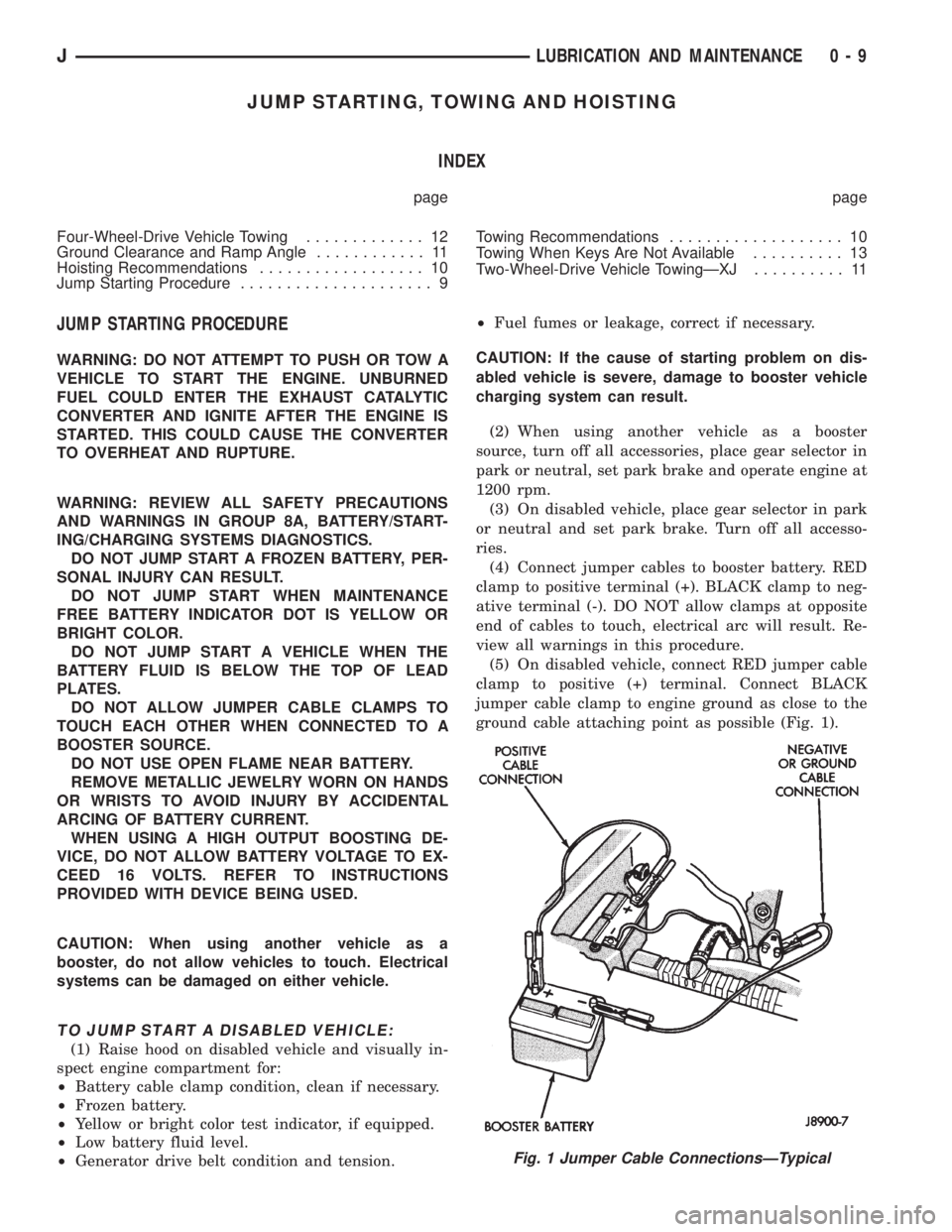
(5) On disabled vehicle, connect RED jumper cable
clamp to positive (+) terminal. Connect BLACK
jumper cable clamp to engine ground as close to the
ground cable attaching point as possible (Fig. 1).
Fig. 1 Jumper Cable ConnectionsÐTypical
JLUBRICATION AND MAINTENANCE 0 - 9
Page 21 of 2198
line. You may encounter fuels containing 3 percent or
more methanol along with other alcohols called cosol-
vents.
Problems that are the result of using methanol/gas-
oline blends are not the responsibility of Chrysler
Corporation. They may not be covered by the vehicle
warranty.
MTBE/ETBE
Gasoline and MTBE (Methyl Tertiary Butyl Ether)
blends are a mixture of unleaded gasoline and up to
15 percent MTBE. Gasoline and ETBE (Ethyl Ter-
tiary Butyl Ether) are blends of gasoline and up to
17 percent ETBE. Gasoline blended with MTBE or
ETBE may be used.
CLEAN AIR GASOLINE
Many gasolines are now being blended that con-
tribute to cleaner air, especially in those areas of the
country where air pollution levels are high. These
new blends provide a cleaner burning fuel and some
are referred to asReformulated Gasoline.
In areas of the country where carbon monoxide lev-
els are high, gasolines are being treated with oxygen-
ated materials such as MTBE, ETBE and ethanol.
Chrysler Corporation supports these efforts toward
cleaner air and recommends the use of these gaso-
lines as they become available.
IGNITION CABLES, DISTRIBUTOR CAP AND
ROTOR
Inspect and test ignition cables, distributor cap and
rotor when the spark plugs are replaced. Oil and
grime should be cleaned from the ignition cables and
distributor cap to avoid possible spark plug fouling.
Mopar Foamy Engine Degreaser or equivalent is rec-
ommended for cleaning the engine compartment. For
proper service and diagnostic procedures refer to
Group 8D, Ignition System.
IGNITION TIMING
The ignition timing for 2.5L and 4.0L engines is
not adjustable. Refer to the specifications listed on
the engine Emission Control Information Label. Re-
fer to Group 25, Emission Control Systems for addi-
tional information.
SPARK PLUGS
Ignition spark plugs should be replaced at the
mileage interval described in the Lubrication and
Maintenance Schedules. Refer to the General Infor-
mation section of this group. For proper service pro-
cedures refer to Group 8D, Ignition Systems.
BATTERY
WARNING: WEAR SAFETY GLASSES, RUBBER
GLOVES AND PROTECTIVE CLOTHING WHEN HAN-DLING/SERVICING A BATTERY. THE BATTERY
ELECTROLYTE CONTAINS SULFURIC ACID AND
WILL CAUSE HARM IF IT CONTACTS SKIN, EYES
OR CLOTHING. IT WILL ALSO DAMAGE PAINTED
(AS WELL AS UN-PAINTED) SURFACES OF A VEHI-
CLE. IF SULFURIC ACID CONTACTS ANY OF
THESE, FLUSH IMMEDIATELY WITH LARGE
AMOUNTS OF WATER. IF SULFURIC ACID CON-
TACTS SKIN OR EYES, GET IMMEDIATE MEDICAL
ATTENTION. DO NOT SMOKE IN THE VICINITY OF A
BATTERY. KEEP OPEN FLAMES AND SPARKS
AWAY FROM BATTERY FILLER CAPS BECAUSE
EXPLOSIVE GAS IS ALWAYS PRESENT.
Inspect battery tray, hold down and terminal con-
nections when other under hood service is performed.
For proper diagnostic procedures refer to Group 8A,
Battery/Starting/Charging System Diagnostics. For
service and cleaning procedures refer to Group 8B,
Battery/Starter Service.
Care should be taken when disposing a bat-
tery after removal from a vehicle. Lead-acid
batteries are highly poisonous and, when indis-
criminately disposed, could create a problem
for the environment. Contact the applicable lo-
cal city or county government agency to deter-
mine where automobile (lead-acid) batteries
can be properly disposed in the local area.
RUBBER AND PLASTIC COMPONENT INSPECTION
CAUTION: Plastic hoses or wire harness covers will
melt or deform when exposed to heat from exhaust
system or engine manifolds.
Position plastic or rubber components away from
moving parts in engine compartment or under vehi-
cle, or damage will result.
Do not allow rubber engine mounts or other com-
ponents to become oil contaminated, repair cause
of oil contamination and clean area.
All rubber and plastic components should be in-
spected when engine compartment or under vehicle
service is performed. When evidence of deterioration
exists, replacement is required. To reduce deteriora-
tion of rubber components, Chrysler Corporation rec-
ommends Mopar Foamy Engine Degreaser or
equivalent be used to clean engine compartment of
oil and road grime.
EMISSION CONTROL SYSTEM
Inspect all emission control components and hoses
when other under hood service is performed. Refer to
emission system Vacuum Hose Label located on the
inside of the hood in the engine compartment and
Group 25, Emission Control Systems for proper ser-
vice procedures.
0 - 20 LUBRICATION AND MAINTENANCEJ
Page 23 of 2198
DRIVETRAIN
INDEX
page page
Automatic Transmission.................... 23
Clutch and Brake Pedal Bushings............. 22
Clutch Master Cylinder..................... 22
Drive Shafts............................. 26Front and Rear Axles...................... 24
Manual Transmission...................... 22
Rubber and Plastic Hoses/Tubing............. 26
Transfer Case (4WD Vehicles)................ 24
CLUTCH AND BRAKE PEDAL BUSHINGS
If the clutch and brake pedal mechanism squeaks,
the pivot bushings should be lubricated. Use Mopar
Multi-Purpose Lubricant, or an equivalent. Refer to
Group 5, Brakes for location of bushings.
CLUTCH MASTER CYLINDER
LEVEL INSPECTION
WARNING: DO NOT ALLOW PETROLEUM OR WA-
TER BASE LIQUIDS TO CONTAMINATE CLUTCH
FLUID, SEAL DAMAGE AND CLUTCH FAILURE CAN
RESULT.
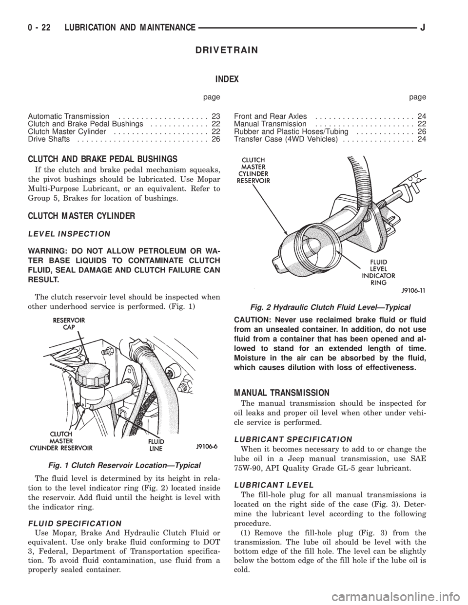
The clutch reservoir level should be inspected when
other underhood service is performed. (Fig. 1)
The fluid level is determined by its height in rela-
tion to the level indicator ring (Fig. 2) located inside
the reservoir. Add fluid until the height is level with
the indicator ring.
FLUID SPECIFICATION
Use Mopar, Brake And Hydraulic Clutch Fluid or
equivalent. Use only brake fluid conforming to DOT
3, Federal, Department of Transportation specifica-
tion. To avoid fluid contamination, use fluid from a
properly sealed container.CAUTION: Never use reclaimed brake fluid or fluid
from an unsealed container. In addition, do not use
fluid from a container that has been opened and al-
lowed to stand for an extended length of time.
Moisture in the air can be absorbed by the fluid,
which causes dilution with loss of effectiveness.
MANUAL TRANSMISSION
The manual transmission should be inspected for
oil leaks and proper oil level when other under vehi-
cle service is performed.
LUBRICANT SPECIFICATION
When it becomes necessary to add to or change the
lube oil in a Jeep manual transmission, use SAE
75W-90, API Quality Grade GL-5 gear lubricant.
LUBRICANT LEVEL
The fill-hole plug for all manual transmissions is
located on the right side of the case (Fig. 3). Deter-
mine the lubricant level according to the following
procedure.
(1) Remove the fill-hole plug (Fig. 3) from the
transmission. The lube oil should be level with the
bottom edge of the fill hole. The level can be slightly
below the bottom edge of the fill hole if the lube oil is
cold.
Fig. 1 Clutch Reservoir LocationÐTypical
Fig. 2 Hydraulic Clutch Fluid LevelÐTypical
0 - 22 LUBRICATION AND MAINTENANCEJ
Page 254 of 2198
(4) For access to radiator draincock, remove radia-
tor grille mounting screws and remove grill. Refer to
Group 23, Body for procedures.
(5) Attach one end of a 24 inch long X 1/4 inch ID
hose to the radiator draincock. Put the other end into
a clean container. Open draincock and drain radiator.
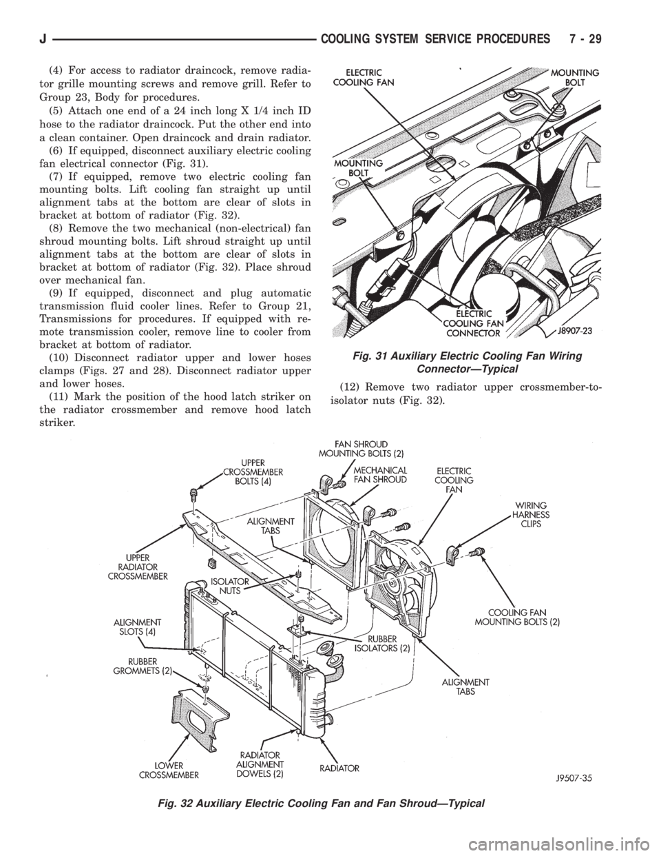
(6) If equipped, disconnect auxiliary electric cooling
fan electrical connector (Fig. 31).
(7) If equipped, remove two electric cooling fan
mounting bolts. Lift cooling fan straight up until
alignment tabs at the bottom are clear of slots in
bracket at bottom of radiator (Fig. 32).
(8) Remove the two mechanical (non-electrical) fan
shroud mounting bolts. Lift shroud straight up until
alignment tabs at the bottom are clear of slots in
bracket at bottom of radiator (Fig. 32). Place shroud
over mechanical fan.
(9) If equipped, disconnect and plug automatic
transmission fluid cooler lines. Refer to Group 21,
Transmissions for procedures. If equipped with re-
mote transmission cooler, remove line to cooler from
bracket at bottom of radiator.
(10) Disconnect radiator upper and lower hoses
clamps (Figs. 27 and 28). Disconnect radiator upper
and lower hoses.
(11) Mark the position of the hood latch striker on
the radiator crossmember and remove hood latch
striker.(12) Remove two radiator upper crossmember-to-
isolator nuts (Fig. 32).
Fig. 31 Auxiliary Electric Cooling Fan Wiring
ConnectorÐTypical
Fig. 32 Auxiliary Electric Cooling Fan and Fan ShroudÐTypical
JCOOLING SYSTEM SERVICE PROCEDURES 7 - 29
Page 281 of 2198
IGNITION-OFF DRAW
GENERAL INFORMATION
Ignition-Off Draw (IOD) refers to power being
drained from the battery with the ignition switch
turned OFF. A normal vehicle electrical system will
draw from 5 to 20 milliamps (0.005 - 0.020 amps).
This is with the ignition switch in the OFF position,
and all non-ignition controlled circuits in proper
working order. The 20 milliamps are needed to sup-
ply PCM memory, digital clock memory, and electron-
ically-tuned radio memory.
A vehicle that has not been operated for approxi-
mately 20 days, may discharge the battery to an in-
adequate level. When a vehicle will not be used for
20 days or more (stored), remove the IOD fuse in the
Power Distribution Center (PDC). This will reduce
battery discharging.
Excessive battery drain can be caused by:
²electrical items left on
²faulty or improperly adjusted switches
²internally shorted generator
²intermittent shorts in the wiring.
If the IOD is over 20 milliamps, the problem must
be found and corrected before replacing a battery. In
most cases, the battery can be charged and returned
to service.
DIAGNOSIS
Testing for high-amperage IOD must be per-
formed first to prevent damage to most milli-
amp meters.
(1) Verify that all electrical accessories are off.
Turn off all lamps, remove ignition key, and close all
doors. If the vehicle is equipped with illuminated en-
try or electronically-tuned radio, allow the systems to
automatically shut off (time out). This may take up
to 3 minutes.
(2) Determine that the underhood lamp is operat-
ing properly, then disconnect or remove bulb.
(3) Disconnect negative cable from battery.
(4) Connect a typical 12-volt test lamp (low-watt-
age bulb) between the negative cable clamp and the
battery negative terminal. Make sure that the doors
remain closed so that illuminated entry is not acti-
vated.The test lamp may light brightly for up to 3 min-
utes, or may not light at all, depending upon the ve-
hicle's electrical equipment. The term brightly, as
used throughout the following tests, implies the
brightness of the test lamp will be the same as if it
were connected across the battery.
The test lamp must be securely clamped to the neg-
ative cable clamp and battery negative terminal. If
the test lamp becomes disconnected during any part
of the IOD test, the electronic timer function will be
activated and all tests must be repeated.
(5) After 3 minutes the test lamp should turn off
or be dimly lit, depending upon the vehicle's electri-
cal equipment. If the test lamp remains brightly lit,
do not disconnect it. Remove each fuse or circuit
breaker (refer to Group 8W - Wiring Diagrams) until
test lamp is either off or dimly lit. This will isolate
each circuit and identify the source of the high-am-
perage draw.
If the test lamp is still brightly lit after disconnect-
ing each fuse and circuit breaker, disconnect the wir-
ing harness from the generator. If test lamp now
turns off or is dimly lit, see Charging System in this
group to diagnose faulty generator. Do not disconnect
the test lamp.
After high-amperage IOD has been corrected, low-
amperage IOD may be checked. It is now safe to in-
stall a milliamp meter to check for low- amperage
IOD.
(6) With test lamp still connected securely, clamp a
milliamp meter between battery negative terminal
and negative cable clamp.
Do not open any doors or turn on any electri-
cal accessories with the test lamp disconnected
or the milliamp meter may be damaged.
(7) Disconnect test lamp. Observe milliamp meter.
The current draw should not exceed 0.020 amp. If
draw exceeds 20 milliamps, isolate each circuit by re-
moving circuit breakers and fuses. The milliamp
meter reading will drop when the source of the draw
is disconnected. Repair this circuit as necessary,
whether a wiring short, incorrect switch adjustment
or a component failure is found.
8A - 10 BATTERY/STARTING/CHARGING SYSTEMS DIAGNOSTICSJ
Page 398 of 2198
HORNS
CONTENTS
page page
DIAGNOSIS............................. 2
GENERAL INFORMATION.................. 1SERVICE PROCEDURES................... 3
SPECIFICATIONS......................... 5
GENERAL INFORMATION
Following are general descriptions of the major
components in the XJ (Cherokee)/YJ (Wrangler) horn
systems. Refer to Group 8W - Wiring Diagrams for
complete circuit descriptions and diagrams.
HORN SWITCH
XJ
Two horn switches are installed in the steering
wheel, one on each side of the center-mounted driv-
er's airbag module. When either switch is depressed
it completes a circuit to ground for the coil side of the
horn relay. The steering wheel and steering column
must be properly grounded for the horn switches to
function. The horn switches are only serviced as a set
with their wiring. If either switch should fail, both
switches must be replaced.
YJ
A single switch is installed in the center of the
steering wheel, directly under the horn button. When
the horn button is depressed the switch completes a
circuit to ground for the coil side of the horn relay.
The steering wheel and steering column must be
properly grounded for the horn switch to function.
The horn switch is available for service.
HORN RELAY
On XJ models, the horn relay is a mini-relay in-
stalled in the relay center, which is mounted to the
lower instrument panel reinforcement inboard of thesteering column. On YJ models, the horn relay is a
ISO relay installed in the Power Distribution Center
(PDC) near the battery tray. Refer to underside of
PDC cover for relay identification.
One side of the horn relay electromagnetic coil re-
ceives battery voltage at all times. When a horn
switch is depressed, the other side of the relay coil is
grounded. The energized relay coil causes the nor-
mally open relay contacts to close, providing battery
voltage to the horn.
If a problem is encountered with a continuously
sounding horn, it can usually be quickly resolved by
removing the horn relay until further diagnosis is
completed.
HORNS
On YJ models, a standard single, low-note, dia-
phragm-type horn is mounted and grounded to the
left inner fender shield under the hood. Dual horns
are standard equipment on XJ models. The high-note
diaphragm-type horn is mounted and grounded to
the left radiator closure panel brace behind the front
bumper. The low-note diaphragm-type horn is con-
nected in parallel with the high-note horn and is
mounted and grounded to the right radiator closure
panel brace behind the front bumper.
On XJ models, a cadmium-plated screw is
used to attach the horns to the body. Do not
substitute other types of screws as they may be-
come corroded and cause a loss of ground.
JHORNS 8G - 1
Page 459 of 2198
BACK-UP/REAR TURN SIGNAL/TAIL LAMP BULB
REPLACEMENTÐXJ
REMOVAL
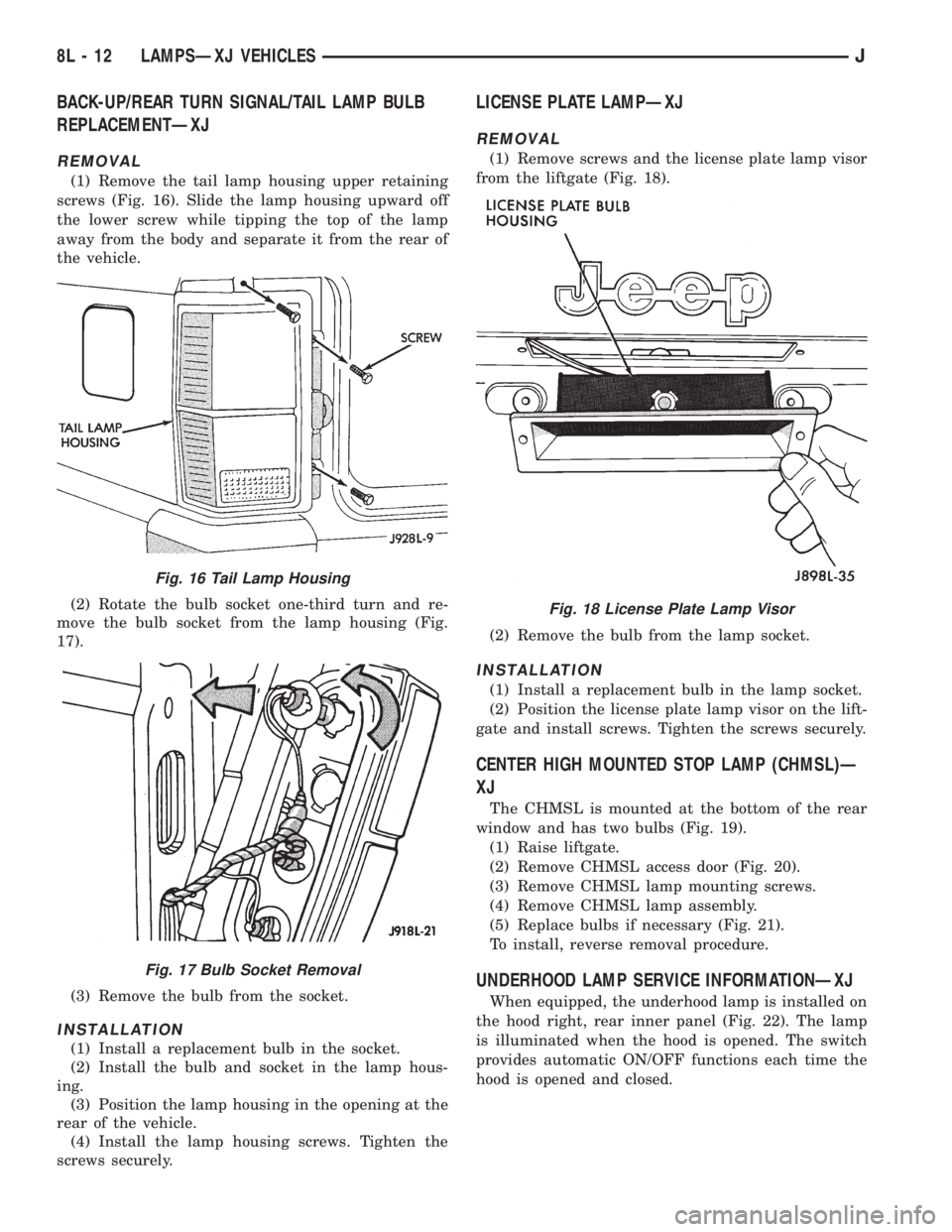
(1) Remove the tail lamp housing upper retaining
screws (Fig. 16). Slide the lamp housing upward off
the lower screw while tipping the top of the lamp
away from the body and separate it from the rear of
the vehicle.
(2) Rotate the bulb socket one-third turn and re-
move the bulb socket from the lamp housing (Fig.
17).
(3) Remove the bulb from the socket.
INSTALLATION
(1) Install a replacement bulb in the socket.
(2) Install the bulb and socket in the lamp hous-
ing.
(3) Position the lamp housing in the opening at the
rear of the vehicle.
(4) Install the lamp housing screws. Tighten the
screws securely.
LICENSE PLATE LAMPÐXJ
REMOVAL
(1) Remove screws and the license plate lamp visor
from the liftgate (Fig. 18).
(2) Remove the bulb from the lamp socket.
INSTALLATION
(1) Install a replacement bulb in the lamp socket.
(2) Position the license plate lamp visor on the lift-
gate and install screws. Tighten the screws securely.
CENTER HIGH MOUNTED STOP LAMP (CHMSL)Ð
XJ
The CHMSL is mounted at the bottom of the rear
window and has two bulbs (Fig. 19).
(1) Raise liftgate.
(2) Remove CHMSL access door (Fig. 20).
(3) Remove CHMSL lamp mounting screws.
(4) Remove CHMSL lamp assembly.
(5) Replace bulbs if necessary (Fig. 21).
To install, reverse removal procedure.
UNDERHOOD LAMP SERVICE INFORMATIONÐXJ
When equipped, the underhood lamp is installed on
the hood right, rear inner panel (Fig. 22). The lamp
is illuminated when the hood is opened. The switch
provides automatic ON/OFF functions each time the
hood is opened and closed.
Fig. 16 Tail Lamp Housing
Fig. 17 Bulb Socket Removal
Fig. 18 License Plate Lamp Visor
8L - 12 LAMPSÐXJ VEHICLESJ
Page 461 of 2198
INSTALLATION
(1) Position the underhood lamp on the hood inner
panel.
(2) Install the attaching screw through the lamp
and into the hood panel. Tighten the screw securely.
(3) Insert a replacement bulb in the lamp base
socket and rotate it clockwise.
(4) Connect the wire harness connector to the
lamp.
SENTINEL HEADLAMP DELAY MODULEÐXJ
SERVICE INFORMATION
The Headlamp Module delays the de-activation of
the headlamps for 45615 seconds after the ignition
switch is turned OFF. The driver engages the module
by turning the ignition switch OFF, then turning the
headlamps OFF.
The headlamp delay module is located behind the
I/P next to the headlamp switch.
HEADLAMP DELAY MODULE REPLACEMENTÐXJ
The headlamp delay module is attached to the in-
side of the instrument panel to the right of the head-
lamp switch.
REMOVAL
(1) Remove the lower instrument panel.(2) Remove the screw that attaches the module to
the inside of the instrument panel.
(3) Disconnect the wire harness connector and re-
move the module from the instrument panel.
INSTALLATION
(1) Position the module inside the I/P and connect
the wire harness connector to the module.
(2) Install the screw that attaches the module to
the inside of the instrument panel.
(3) Remove the lower instrument panel.
HEADLAMP DELAY FUNCTION TROUBLE
DIAGNOSISÐXJ
DELAY FUNCTION INOPERATIVE
(1) Remove, inspect and test the HD LP DLY fuse.
Replace if defective.
(2) Remove the delay module from the I/P. Do not
disconnect the wire harness connector. Turn the igni-
tion switch to the RUN position. Place the headlamp
switch in headlamps ON position. Turn the ignition
to the OFF position for a resistance test.
(3) Measure the resistance from the delay module
terminal 4 to vehicle body ground. The ohmmeter
should indicate zero ohms. If not, repair the open cir-
cuit in the wire harness to vehicle body ground.
(4) Measure the voltage between the delay module
terminal 8 and vehicle body ground. The voltmeter
should indicate battery voltage. If not, repair the
open circuit in the wire harness to the instrument
cluster indicator connector terminal 14.
(5) Measure the voltage between the delay module
terminal 6 and vehicle body ground. The voltmeter
should indicate battery voltage. If not, repair the
open circuit in the wire harness to the headlamp
switch.
(6) Measure the voltage between the delay module
terminal 2 and vehicle body ground. The voltmeter
should indicate battery voltage. If not, repair the
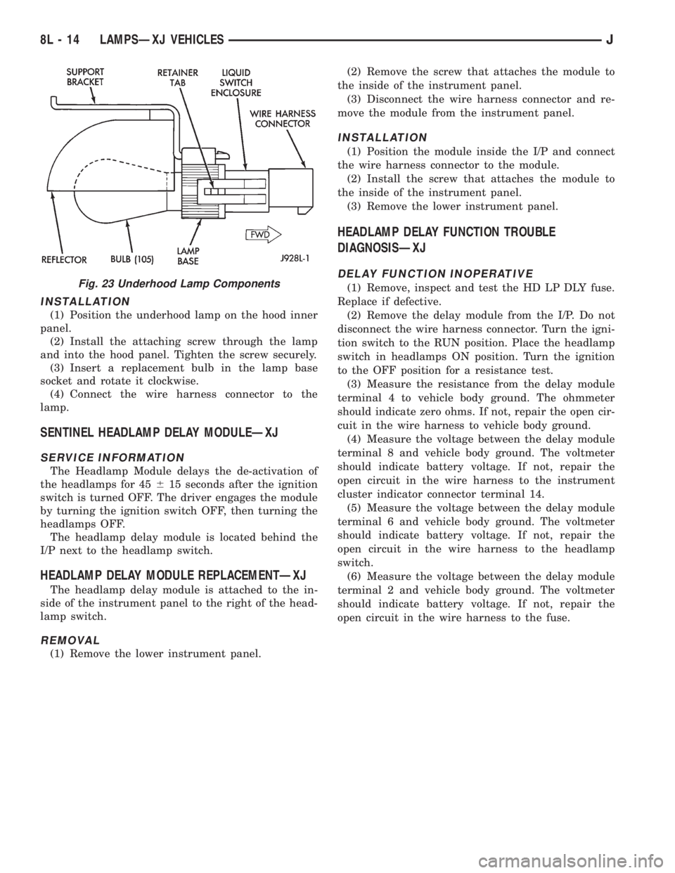
open circuit in the wire harness to the fuse.Fig. 23 Underhood Lamp Components
8L - 14 LAMPSÐXJ VEHICLESJ
Page 475 of 2198
(9) Raise and support the A/C evaporator housing
(Fig. 13).
(10) Install the evaporator housing-to-instrument
panel screws and evaporator support bracket screw.
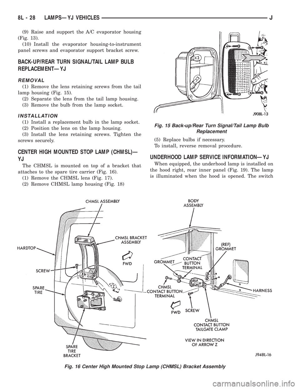
BACK-UP/REAR TURN SIGNAL/TAIL LAMP BULB
REPLACEMENTÐYJ
REMOVAL
(1) Remove the lens retaining screws from the tail
lamp housing (Fig. 15).
(2) Separate the lens from the tail lamp housing.
(3) Remove the bulb from the lamp socket.
INSTALLATION
(1) Install a replacement bulb in the lamp socket.
(2) Position the lens on the lamp housing.
(3) Install the lens retaining screws. Tighten the
screws securely.
CENTER HIGH MOUNTED STOP LAMP (CHMSL)Ð
YJ
The CHMSL is mounted on top of a bracket that
attaches to the spare tire carrier (Fig. 16).
(1) Remove the CHMSL lens (Fig. 17).
(2) Remove CHMSL lamp housing (Fig. 18)(5) Replace bulbs if necessary.
To install, reverse removal procedure.
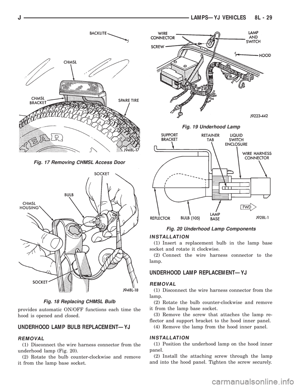
UNDERHOOD LAMP SERVICE INFORMATIONÐYJ
When equipped, the underhood lamp is installed on
the hood right, rear inner panel (Fig. 19). The lamp
is illuminated when the hood is opened. The switch
Fig. 15 Back-up/Rear Turn Signal/Tail Lamp Bulb
Replacement
Fig. 16 Center High Mounted Stop Lamp (CHMSL) Bracket Assembly
8L - 28 LAMPSÐYJ VEHICLESJ
Page 476 of 2198
provides automatic ON/OFF functions each time the
hood is opened and closed.
UNDERHOOD LAMP BULB REPLACEMENTÐYJ
REMOVAL
(1) Disconnect the wire harness connector from the
underhood lamp (Fig. 20).
(2) Rotate the bulb counter-clockwise and remove
it from the lamp base socket.
INSTALLATION
(1) Insert a replacement bulb in the lamp base
socket and rotate it clockwise.
(2) Connect the wire harness connector to the
lamp.
UNDERHOOD LAMP REPLACEMENTÐYJ
REMOVAL
(1) Disconnect the wire harness connector from the
lamp.
(2) Rotate the bulb counter-clockwise and remove
it from the lamp base socket.
(3) Remove the screw that attaches the lamp re-
flector and support bracket to the hood inner panel.
(4) Remove the lamp from the hood inner panel.
INSTALLATION
(1) Position the underhood lamp on the hood inner
panel.
(2) Install the attaching screw through the lamp
and into the hood panel. Tighten the screw securely.
Fig. 17 Removing CHMSL Access Door
Fig. 18 Replacing CHMSL Bulb
Fig. 19 Underhood Lamp
Fig. 20 Underhood Lamp Components
JLAMPSÐYJ VEHICLES 8L - 29