engine JEEP CHEROKEE 2014 KL / 5.G User Guide
[x] Cancel search | Manufacturer: JEEP, Model Year: 2014, Model line: CHEROKEE, Model: JEEP CHEROKEE 2014 KL / 5.GPages: 204, PDF Size: 3.84 MB
Page 3 of 204
INTRODUCTION/WELCOME
WELCOME FROM CHRYSLER
GROUP LLC.................. 3
CONTROLS AT A GLANCE
DRIVER COCKPIT .............. 6
INSTRUMENT CLUSTER .......... 8
GETTING STARTED
KEYFOB ................... 10
REMOTE START............... 12
VEHICLE SECURITY ALARM ....... 13
KEYLESS ENTER-N-GO™ ......... 14
SEATBELT .................. 18
SUPPLEMENTAL RESTRAINT SYSTEM
(SRS) — AIR BAGS ............ 19
CHILD RESTRAINTS ............ 20
FRONT SEATS ................ 25
REAR SEATS ................ 27
HEATED/VENTILATED SEATS ....... 28
HEATED STEERING WHEEL ....... 29
TILT/TELESCOPING STEERING
COLUMN ................... 30
OPERATING YOUR VEHICLE
ENGINE BREAK-IN
RECOMMENDATIONS ........... 31
TURN SIGNAL/HIGH BEAM LEVER . . . 31
HEADLIGHT SWITCH ............ 32
WIPER/WASHER LEVER .......... 33
SPEED CONTROL .............. 34
ADAPTIVE CRUISE CONTROL (ACC) . . . 36
FORWARD COLLISION WARNING (FCW)
WITHMITIGATION ............. 39
MANUAL CLIMATE CONTROLS WITHOUT
TOUCHSCREEN ............... 41
MANUAL CLIMATE CONTROLS WITH
TOUCHSCREEN ............... 42
AUTOMATIC TEMPERATURE
CONTROLS (ATC) .............. 43
ELECTRIC PARK BRAKE .......... 45
PARKSENSE
®................ 46
LANESENSE ................. 48
PARKVIEW
®REAR BACK-UP
CAMERA ................... 49
POWER SUNROOF ............. 50
WIND BUFFETING ............. 53
ELECTRONICS
YOUR VEHICLE'S SOUND SYSTEM . . . 54
IDENTIFYING YOUR RADIO ........ 56
Uconnect
®ACCESS ............. 57 Uconnect
®5.0 ................ 73
Uconnect®8.4A ............... 81
Uconnect®8.4AN ............. 100
STEERING WHEEL AUDIO
CONTROLS ................. 120
ELECTRONIC VEHICLE INFORMATION
CENTER (EVIC) .............. 121
PROGRAMMABLE FEATURES ...... 122
UNIVERSAL GARAGE DOOR OPENER
(HomeLink
®) ................ 122
POWER INVERTER ............ 125
POWER OUTLET ............. 126
WIRELESS CHARGING PAD ....... 128
OFF-ROAD CAPABILITIES
FOUR-WHEEL DRIVE OPERATION . . . 131
SELEC-TERRAIN™............ 134
UTILITY
CARGO AREA FEATURES ........ 135
TRAILER TOWING WEIGHTS (MAXIMUM
TRAILER WEIGHT RATINGS) ...... 135
RECREATIONAL TOWING (BEHIND
MOTORHOME, ETC.) ........... 136
WHATTODOIN
EMERGENCIES
ROADSIDE ASSISTANCE ......... 141
INSTRUMENT CLUSTER WARNING
LIGHTS ................... 141
INSTRUMENT CLUSTER INDICATOR
LIGHTS ................... 148
IF YOUR ENGINE OVERHEATS ..... 151
TIREFIT KIT ................ 151
JACKING AND TIRE CHANGING .... 158
JUMP-STARTING ............. 163
FREEING A STUCK VEHICLE ...... 166
RECOVERY STRAP ............ 167
SHIFT LEVER OVERRIDE ........ 167
TOWING A DISABLED VEHICLE .... 168
EVENT DATA RECORDER (EDR) .... 169
MAINTAINING YOUR VEHICLE
OPENING THE HOOD.......... 170
ENGINE COMPARTMENT ........ 171
FLUIDS AND CAPACITIES ........ 173
MAINTENANCE SCHEDULE ...... 175
FUSES .................... 179
TIRE PRESSURES ............. 184
WHEEL AND WHEEL TRIM CARE . . . 185
REPLACEMENT BULBS ......... 185
TABLE OF CONTENTS
Page 9 of 204
11. Switch Panel• ParkSense
®pg. 46
• Hazard Switch
• Lane Sense pg. 48
• Forward Collision Warning pg. 39
12. Climate Controls pg. 43
13. Shifter
14. Engine Start/Stop pg. 16
15. Speed Control pg. 34
16. Opening The Hood pg. 170
17. Power Door Locks
18. Power Windows
19. Power Mirror Switch
CONTROLS AT A GLANCE
7
Page 10 of 204
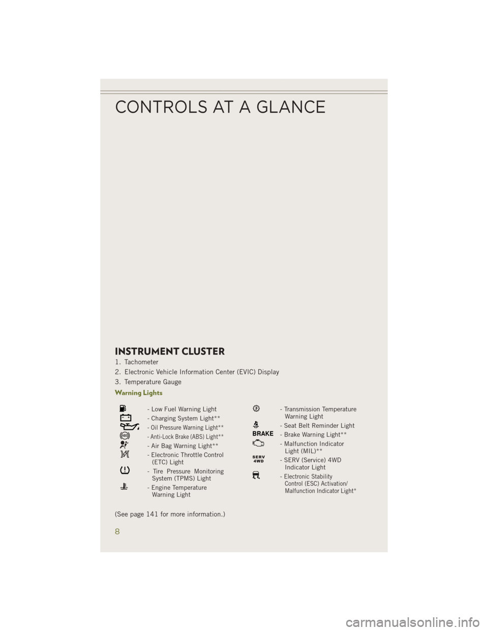
INSTRUMENT CLUSTER
1. Tachometer
2. Electronic Vehicle Information Center (EVIC) Display
3. Temperature Gauge
Warning Lights
- Low Fuel Warning Light
- Charging System Light**
- Oil Pressure Warning Light**
- Anti-Lock Brake (ABS) Light**
- Air Bag Warning Light**
- Electronic Throttle Control(ETC) Light
- Tire Pressure MonitoringSystem (TPMS) Light
- Engine TemperatureWarning Light
- Transmission TemperatureWarning Light
- Seat Belt Reminder Light
BRAKE- Brake Warning Light**
- Malfunction IndicatorLight (MIL)**
- SERV (Service) 4WDIndicator Light
-Electronic StabilityControl (ESC) Activation/
Malfunction Indicator Light*
(See page 141 for more information.)
CONTROLS AT A GLANCE
8
Page 13 of 204
NOTE:
In case the ignition switch does not change with the push of a button, the RKE
transmitter (Key Fob) may have a low or dead battery. In this situation a back up
method can be used to operate the ignition switch. Put the nose side (side opposite
of the emergency key) of the Key Fob against the ENGINE START/STOP button and
push to operate the ignition switch.
• The Ignition Node Module (IGNM) op-erates similar to an ignition switch. It
has four operating positions, three with
detents and one that is spring-loaded.
The detent positions are OFF, ACC, and
ON/RUN. The START position is a
spring-loaded momentary contact po-
sition. When released from the START
position, the switch automatically re-
turns to the ON/RUN position.
Locking And Unlocking The
Doors/Liftgate
• Press the LOCK button once to lock allthe doors and the liftgate. Press the
UNLOCK button once to unlock the
driver’s door only and twice within five
seconds to unlock all the doors and the
liftgate.
• All doors can be programmed to un- lock on the first press of the UNLOCK
button. Refer to Programmable Fea-
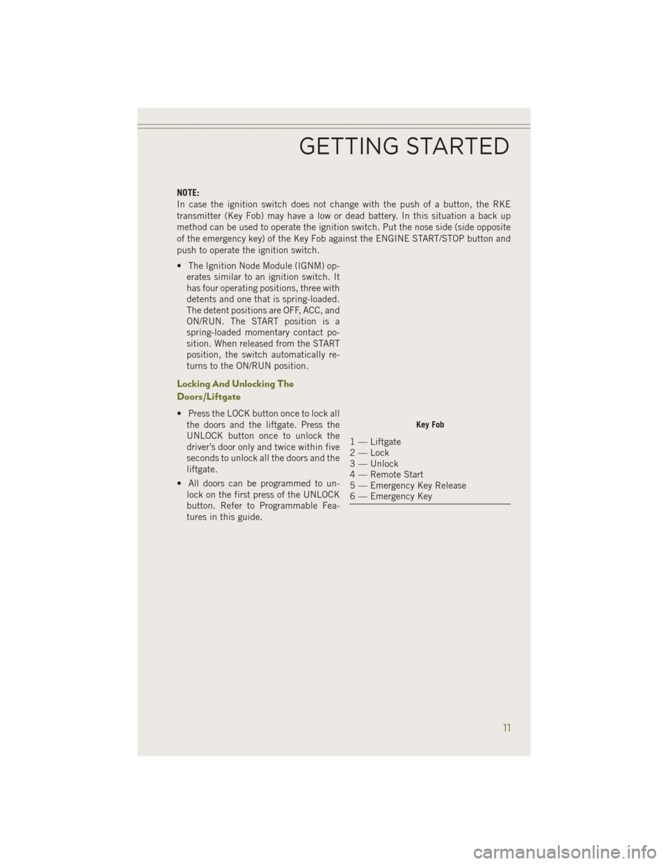
tures in this guide.Key Fob
1 — Liftgate
2 — Lock
3 — Unlock
4 — Remote Start
5 — Emergency Key Release
6 — Emergency Key
GETTING STARTED
11
Page 14 of 204
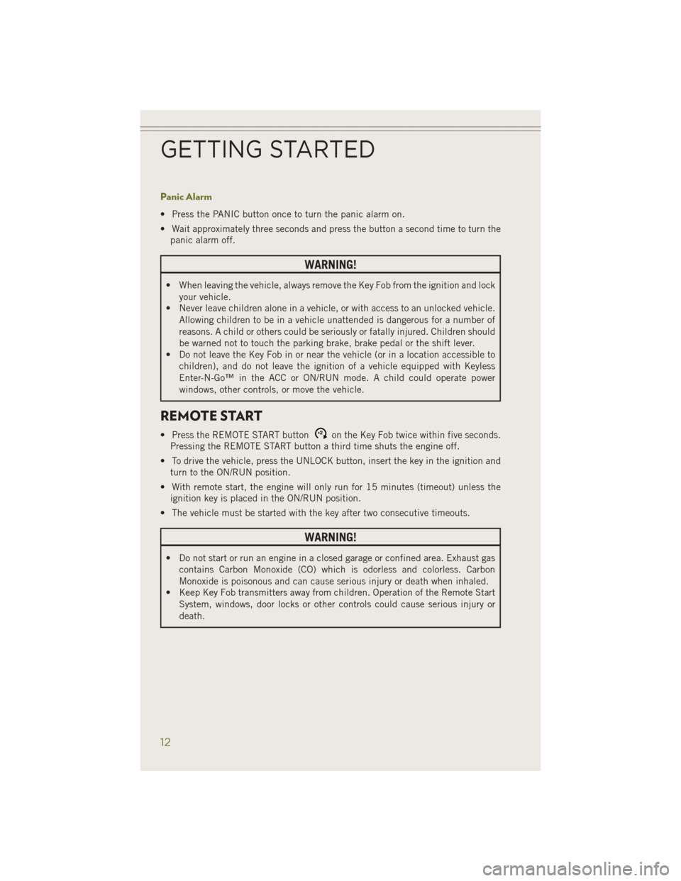
Panic Alarm
• Press the PANIC button once to turn the panic alarm on.
• Wait approximately three seconds and press the button a second time to turn thepanic alarm off.
WARNING!
• When leaving the vehicle, always remove the Key Fob from the ignition and lock
your vehicle.
• Never leave children alone in a vehicle, or with access to an unlocked vehicle.
Allowing children to be in a vehicle unattended is dangerous for a number of
reasons. A child or others could be seriously or fatally injured. Children should
be warned not to touch the parking brake, brake pedal or the shift lever.
• Do not leave the Key Fob in or near the vehicle (or in a location accessible to
children), and do not leave the ignition of a vehicle equipped with Keyless
Enter-N-Go™ in the ACC or ON/RUN mode. A child could operate power
windows, other controls, or move the vehicle.
REMOTE START
• Press the REMOTE START buttonx2on the Key Fob twice within five seconds.
Pressing the REMOTE START button a third time shuts the engine off.
• To drive the vehicle, press the UNLOCK button, insert the key in the ignition and turn to the ON/RUN position.
• With remote start, the engine will only run for 15 minutes (timeout) unless the ignition key is placed in the ON/RUN position.
• The vehicle must be started with the key after two consecutive timeouts.
WARNING!
• Do not start or run an engine in a closed garage or confined area. Exhaust gas contains Carbon Monoxide (CO) which is odorless and colorless. Carbon
Monoxide is poisonous and can cause serious injury or death when inhaled.
• Keep Key Fob transmitters away from children. Operation of the Remote Start
System, windows, door locks or other controls could cause serious injury or
death.
GETTING STARTED
12
Page 18 of 204
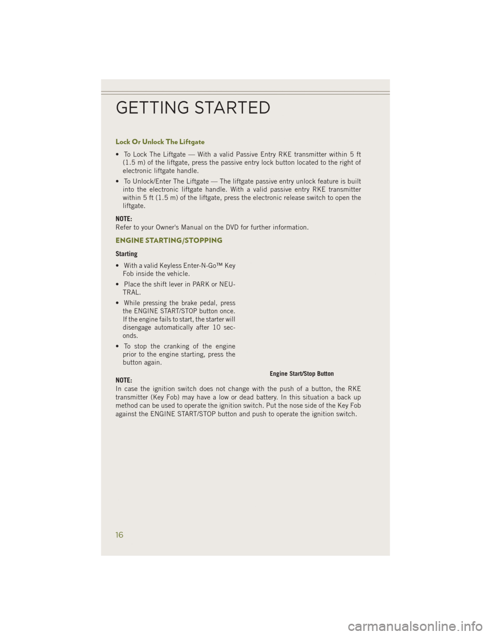
Lock Or Unlock The Liftgate
• To Lock The Liftgate — With a valid Passive Entry RKE transmitter within 5 ft(1.5 m) of the liftgate, press the passive entry lock button located to the right of
electronic liftgate handle.
• To Unlock/Enter The Liftgate — The liftgate passive entry unlock feature is built into the electronic liftgate handle. With a valid passive entry RKE transmitter
within 5 ft (1.5 m) of the liftgate, press the electronic release switch to open the
liftgate.
NOTE:
Refer to your Owner's Manual on the DVD for further information.
ENGINE STARTING/STOPPING
Starting
• With a valid Keyless Enter-N-Go™ Key Fob inside the vehicle.
• Place the shift lever in PARK or NEU- TRAL.
•
While pressing the brake pedal, press
the ENGINE START/STOP button once.
If the engine fails to start, the starter will
disengage automatically after 10 sec-
onds.
• To stop the cranking of the engine prior to the engine starting, press the
button again.
NOTE:
In case the ignition switch does not change with the push of a button, the RKE
transmitter (Key Fob) may have a low or dead battery. In this situation a back up
method can be used to operate the ignition switch. Put the nose side of the Key Fob
against the ENGINE START/STOP button and push to operate the ignition switch.
Engine Start/Stop Button
GETTING STARTED
16
Page 19 of 204
Stopping
• Place the shift lever in PARK.
• Press the ENGINE START/STOP button once. The ignition switch will return to theOFF position.
•
If the shift lever is not in PARK, the ENGINE START/STOP button must be held for two
seconds and vehicle speed must be above 5 mph (8 km/h) before the engine will shut off.
Accessory Positions With Engine Off
NOTE:
The following functions are with the driver’s foot OFF the Brake Pedal (Transmission
in PARK or NEUTRAL Position).
Starting With The Ignition Switch In The OFF Position:
• Press the ENGINE START/STOP button once to change the ignition switch to the ACC position.
• Press the ENGINE START/STOP button a second time to change the ignition switch to the ON/RUN position.
• Press the ENGINE START/STOP button a third time to return the ignition switch to the OFF position.
NOTE:
If the ignition switch is left in the ACC or
ON/RUN (engine not running) position
and the transmission is in PARK, the
system will automatically time out after
30 minutes of inactivity and the ignition
will switch to the OFF position.
• In case the ignition switch does not change with the push of a button, the
RKE transmitter (Key Fob) may have a
low or dead battery. In this situation a
back up method can be used to operate the ignition switch. Put the nose side (side
opposite of the emergency key) of the Key Fob against the ENGINE START/STOP
button and push to operate the ignition switch.
GETTING STARTED
17
Page 33 of 204
ENGINE BREAK-IN RECOMMENDATIONS
A long break-in period is not required for the engine and drivetrain (transmission and
axle) in your vehicle.
Drive moderately during the first 300 miles (500 km). After the initial 60 miles
(100 km), speeds up to 50 or 55 mph (80 or 90 km/h) are desirable.
While cruising, brief full-throttle acceleration within the limits of local traffic laws
contributes to a good break-in. Wide-open throttle acceleration in low gear can be
detrimental and should be avoided.
The engine oil installed in the engine at the factory is a high-quality energy
conserving type lubricant. Oil changes should be consistent with anticipated climate
conditions under which vehicle operations will occur. For the recommended viscosity
and quality grades, refer to “Maintaining Your Vehicle.”
NOTE:
A new engine may consume some oil during its first few thousand miles (kilometers)
of operation. This should be considered a normal part of the break-in and not
interpreted as an indication of an engine problem or malfunction.
CAUTION!
Never use Non-Detergent Oil or Straight Mineral Oil in the engine or damage may result.
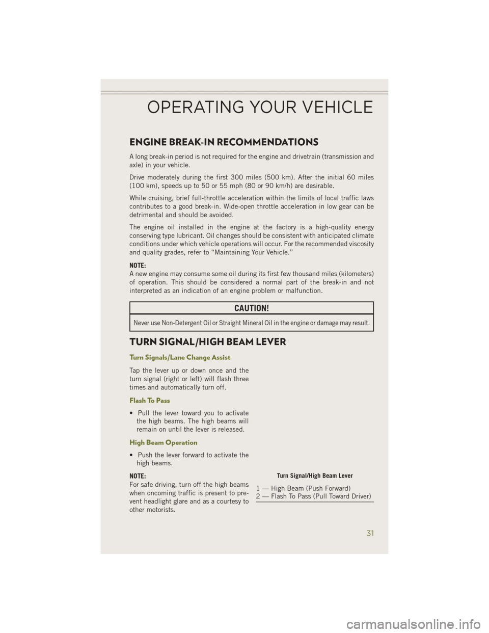
TURN SIGNAL/HIGH BEAM LEVER
Turn Signals/Lane Change Assist
Tap the lever up or down once and the
turn signal (right or left) will flash three
times and automatically turn off.
Flash To Pass
• Pull the lever toward you to activatethe high beams. The high beams will
remain on until the lever is released.
High Beam Operation
• Push the lever forward to activate thehigh beams.
NOTE:
For safe driving, turn off the high beams
when oncoming traffic is present to pre-
vent headlight glare and as a courtesy to
other motorists.
Turn Signal/High Beam Lever
1 — High Beam (Push Forward)
2 — Flash To Pass (Pull Toward Driver)
OPERATING YOUR VEHICLE
31
Page 47 of 204
Air Recirculation
• Use Recirculation for maximum A/C operation.
• For window defogging, turn the Recirculation button off.
• If the Recirculation button is pushed while in the AUTO mode, the indicator lightmay flash three times to indicate the cabin air is being controlled automatically.
Heated Mirrors
The mirrors are heated to melt frost or ice. This feature is activated whenever you turn
on the rear window defroster.
ELECTRIC PARK BRAKE
• Your vehicle is equipped with a newElectric Park Brake System (EPB) that
offers greater convenience.
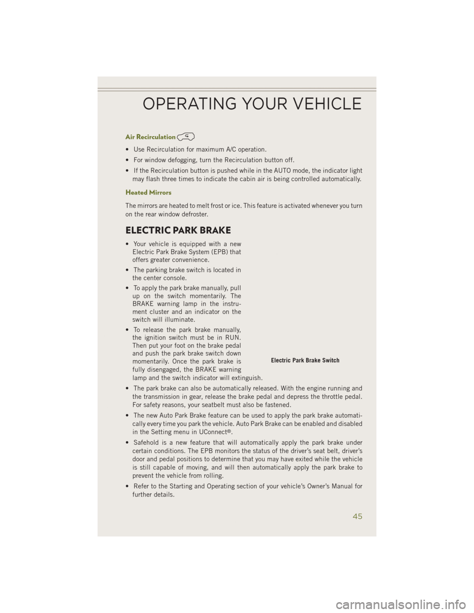
• The parking brake switch is located in the center console.
• To apply the park brake manually, pull up on the switch momentarily. The
BRAKE warning lamp in the instru-
ment cluster and an indicator on the
switch will illuminate.
• To release the park brake manually, the ignition switch must be in RUN.
Then put your foot on the brake pedal
and push the park brake switch down
momentarily. Once the park brake is
fully disengaged, the BRAKE warning
lamp and the switch indicator will extinguish.
• The park brake can also be automatically released. With the engine running and the transmission in gear, release the brake pedal and depress the throttle pedal.
For safety reasons, your seatbelt must also be fastened.
• The new Auto Park Brake feature can be used to apply the park brake automati- cally every time you park the vehicle. Auto Park Brake can be enabled and disabled
in the Setting menu in UConnect
®.
• Safehold is a new feature that will automatically apply the park brake under certain conditions. The EPB monitors the status of the driver’s seat belt, driver’s
door and pedal positions to determine that you may have exited while the vehicle
is still capable of moving, and will then automatically apply the park brake to
prevent the vehicle from rolling.
• Refer to the Starting and Operating section of your vehicle’s Owner’s Manual for further details.
Electric Park Brake Switch
OPERATING YOUR VEHICLE
45
Page 61 of 204
Uconnect® Access Registration (Uconnect® 8.4AN Only, U.S. 48 Contiguous
States And Alaska)
NOTE:
Should you require assistance anytime during the registration process, simply call
Uconnect
®Care at 855-792-4241.
1. From the parked vehicle with the radio touchscreen powered on, select the “Apps” button on the touchscreen located near the bottom right-hand corner.
2. Press “Register” if you see a reminder screen or select “Uconnect Registration” under the 'Favorites' tab.
3. The Uconnect
®Access Registration App will open and display step-by-step
instructions to start your registration.
4. Enter your email address into the radio touchscreen.
5. A message will display on the touchscreen indicating your email submission was accepted.
6. At home, or wherever you access your email, look for an email from Uconnect
®
Access that contains your personalized registration link. If you don't see it, check
your spam or junk email folder. Open the email and click on the link to continue
registering online.
NOTE:
For security reasons, this link is valid for 72 hours from the time you submit your
email address into the radio touchscreen. If the link has expired, start the process
over (see step 1).
7. You are now registered for your Uconnect
®Access Trial! Apps will be downloaded
the next time you start your vehicle. It may take over 30 minutes for all of the Apps
to install. If the Apps have not appeared after 72 hours, please contact
Uconnect
®Care at 855-792-4241.
8. Get to know Uconnect
®Access! We recommend:
• Go to moparownerconnect.com and log in using the email address and password you established while registering. Go to the Learn & Use tab for complete
information on using Uconnect
®Access.
• If you have a smartphone, download the Uconnect
®Access App and set up your
Via Mobile features. See instructions below.
Download The Uconnect® Access App
If you own a compatible Apple or Android®powered device, the Uconnect Access
App allows you to remotely lock or unlock your doors, start your engine or activate
your horn and lights from virtually anywhere (Vehicle must be within the United
States and have network coverage). You can download the App from Mopar Owner
Connect or from the Apple App or Google Play store. For Uconnect
®phone
compatibility - visit UconnectPhone.com or call 1–877–855–8400.
ELECTRONICS
59