lumbar support JEEP CHEROKEE 2014 KL / 5.G User Guide
[x] Cancel search | Manufacturer: JEEP, Model Year: 2014, Model line: CHEROKEE, Model: JEEP CHEROKEE 2014 KL / 5.GPages: 204, PDF Size: 3.84 MB
Page 27 of 204

FRONT SEATS
Power Seats
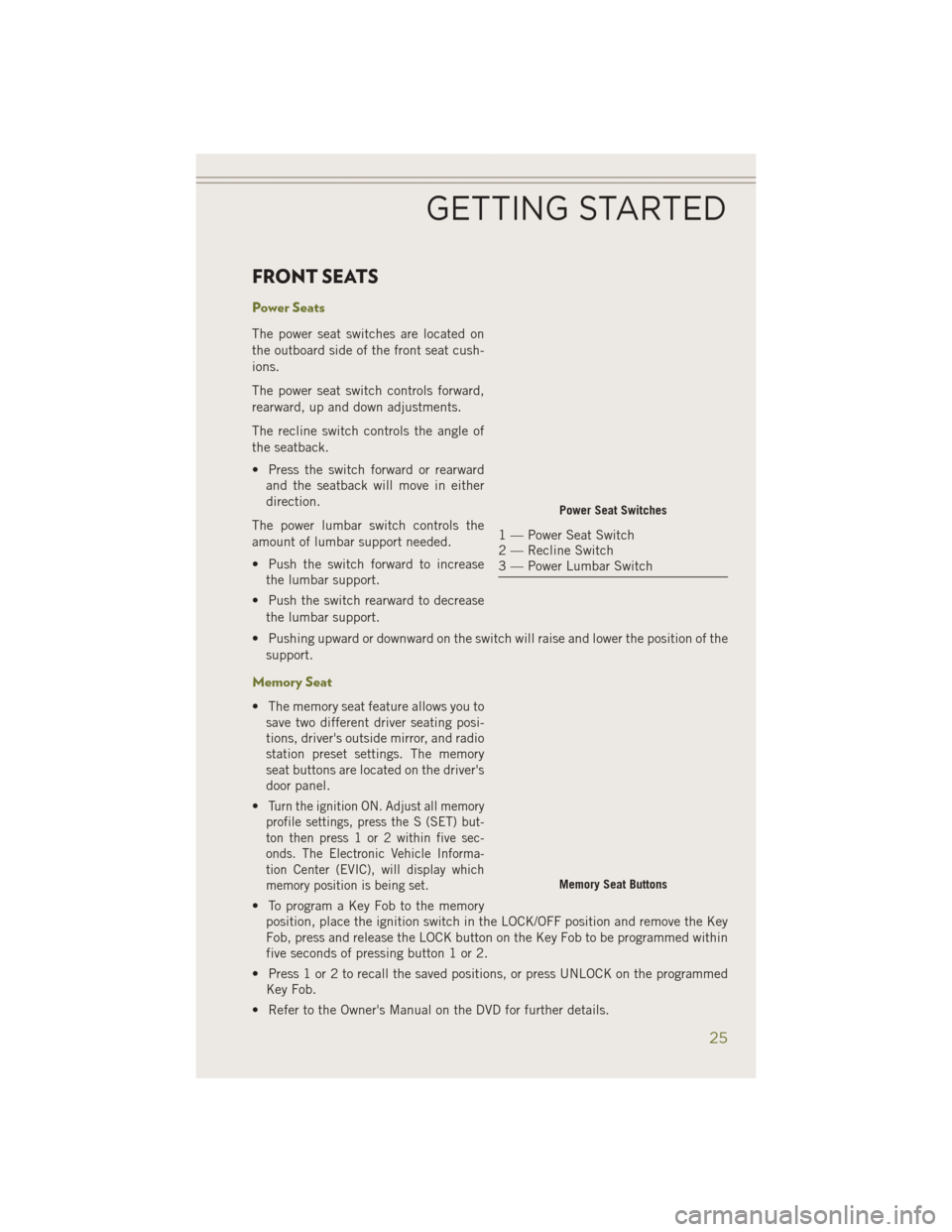
The power seat switches are located on
the outboard side of the front seat cush-
ions.
The power seat switch controls forward,
rearward, up and down adjustments.
The recline switch controls the angle of
the seatback.
• Press the switch forward or rearwardand the seatback will move in either
direction.
The power lumbar switch controls the
amount of lumbar support needed.
• Push the switch forward to increase the lumbar support.
• Push the switch rearward to decrease the lumbar support.
• Pushing upward or downward on the switch will raise and lower the position of the support.
Memory Seat
• The memory seat feature allows you tosave two different driver seating posi-
tions, driver's outside mirror, and radio
station preset settings. The memory
seat buttons are located on the driver's
door panel.
•
Turn the ignition ON. Adjust all memory
profile settings, press the S (SET) but-
ton then press 1 or 2 within five sec-
onds. The Electronic Vehicle Informa-
tion Center (EVIC), will display which
memory position is being set.
• To program a Key Fob to the memory position, place the ignition switch in the LOCK/OFF position and remove the Key
Fob, press and release the LOCK button on the Key Fob to be programmed within
five seconds of pressing button 1 or 2.
• Press 1 or 2 to recall the saved positions, or press UNLOCK on the programmed Key Fob.
• Refer to the Owner's Manual on the DVD for further details.
Power Seat Switches
1 — Power Seat Switch
2 — Recline Switch
3 — Power Lumbar Switch
Memory Seat Buttons
GETTING STARTED
25
Page 185 of 204

Cavity Blade Fuse Cartridge FuseDescription
F99 —30 Amp Pink Trailer Tow Module — If
Equipped With GasolineEngine
F100 — — Not Used
CAUTION!
• When installing the power distribution center cover, it is important to ensure
the cover is properly positioned and fully latched. Failure to do so may allow
water to get into the power distribution center and possibly result in an
electrical system failure.
•
When replacing a blown fuse, it is important to use only a fuse having the correct
amperage rating. The use of a fuse with a rating other than indicated may result
in a dangerous electrical system overload. If a properly rated fuse continues to
blow, it indicates a problem in the circuit that must be corrected.
Interior Fuses
The interior fuse panel is located in the passenger compartment on the left side dash
panel under the instrument panel.
Cavity Blade Fuse Description
F13 15 Amp Blue Low Beam Left
F32 10 Amp Red Interior Lighting
F36 10 Amp Red Intrusion Module/Siren – If Equipped
F38 20 Amp Yellow Deadbolt All Unlock
F43 20 Amp Yellow Washer Pump Front
F48 25 Amp Clear Fog Lamp Rear Left/Right – If Equipped
F49 7.5 Amp Brown Lumbar Support
F50 7.5 Amp Brown Wireless Charging Pad – If Equipped
F51 10 Amp Red Driver Window Switch/Power Mirrors – If
Equipped
F53 7.5 Amp Brown UCI Port (USB & AUX)
F89 10 Amp Red Door Locks – Driver Unlock
F91 7.5 Amp Brown Fog Lamp Front Left
F92 7.5 Amp Brown Fog Lamp Front Right
F93 10 Amp Red Low Beam Right
MAINTAINING YOUR VEHICLE
183