warning light JEEP CHEROKEE 2014 KL / 5.G User Guide
[x] Cancel search | Manufacturer: JEEP, Model Year: 2014, Model line: CHEROKEE, Model: JEEP CHEROKEE 2014 KL / 5.GPages: 204, PDF Size: 3.84 MB
Page 3 of 204
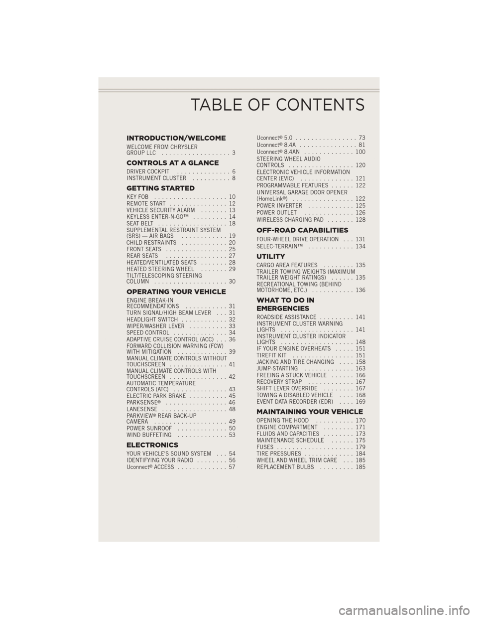
INTRODUCTION/WELCOME
WELCOME FROM CHRYSLER
GROUP LLC.................. 3
CONTROLS AT A GLANCE
DRIVER COCKPIT .............. 6
INSTRUMENT CLUSTER .......... 8
GETTING STARTED
KEYFOB ................... 10
REMOTE START............... 12
VEHICLE SECURITY ALARM ....... 13
KEYLESS ENTER-N-GO™ ......... 14
SEATBELT .................. 18
SUPPLEMENTAL RESTRAINT SYSTEM
(SRS) — AIR BAGS ............ 19
CHILD RESTRAINTS ............ 20
FRONT SEATS ................ 25
REAR SEATS ................ 27
HEATED/VENTILATED SEATS ....... 28
HEATED STEERING WHEEL ....... 29
TILT/TELESCOPING STEERING
COLUMN ................... 30
OPERATING YOUR VEHICLE
ENGINE BREAK-IN
RECOMMENDATIONS ........... 31
TURN SIGNAL/HIGH BEAM LEVER . . . 31
HEADLIGHT SWITCH ............ 32
WIPER/WASHER LEVER .......... 33
SPEED CONTROL .............. 34
ADAPTIVE CRUISE CONTROL (ACC) . . . 36
FORWARD COLLISION WARNING (FCW)
WITHMITIGATION ............. 39
MANUAL CLIMATE CONTROLS WITHOUT
TOUCHSCREEN ............... 41
MANUAL CLIMATE CONTROLS WITH
TOUCHSCREEN ............... 42
AUTOMATIC TEMPERATURE
CONTROLS (ATC) .............. 43
ELECTRIC PARK BRAKE .......... 45
PARKSENSE
®................ 46
LANESENSE ................. 48
PARKVIEW
®REAR BACK-UP
CAMERA ................... 49
POWER SUNROOF ............. 50
WIND BUFFETING ............. 53
ELECTRONICS
YOUR VEHICLE'S SOUND SYSTEM . . . 54
IDENTIFYING YOUR RADIO ........ 56
Uconnect
®ACCESS ............. 57 Uconnect
®5.0 ................ 73
Uconnect®8.4A ............... 81
Uconnect®8.4AN ............. 100
STEERING WHEEL AUDIO
CONTROLS ................. 120
ELECTRONIC VEHICLE INFORMATION
CENTER (EVIC) .............. 121
PROGRAMMABLE FEATURES ...... 122
UNIVERSAL GARAGE DOOR OPENER
(HomeLink
®) ................ 122
POWER INVERTER ............ 125
POWER OUTLET ............. 126
WIRELESS CHARGING PAD ....... 128
OFF-ROAD CAPABILITIES
FOUR-WHEEL DRIVE OPERATION . . . 131
SELEC-TERRAIN™............ 134
UTILITY
CARGO AREA FEATURES ........ 135
TRAILER TOWING WEIGHTS (MAXIMUM
TRAILER WEIGHT RATINGS) ...... 135
RECREATIONAL TOWING (BEHIND
MOTORHOME, ETC.) ........... 136
WHATTODOIN
EMERGENCIES
ROADSIDE ASSISTANCE ......... 141
INSTRUMENT CLUSTER WARNING
LIGHTS ................... 141
INSTRUMENT CLUSTER INDICATOR
LIGHTS ................... 148
IF YOUR ENGINE OVERHEATS ..... 151
TIREFIT KIT ................ 151
JACKING AND TIRE CHANGING .... 158
JUMP-STARTING ............. 163
FREEING A STUCK VEHICLE ...... 166
RECOVERY STRAP ............ 167
SHIFT LEVER OVERRIDE ........ 167
TOWING A DISABLED VEHICLE .... 168
EVENT DATA RECORDER (EDR) .... 169
MAINTAINING YOUR VEHICLE
OPENING THE HOOD.......... 170
ENGINE COMPARTMENT ........ 171
FLUIDS AND CAPACITIES ........ 173
MAINTENANCE SCHEDULE ...... 175
FUSES .................... 179
TIRE PRESSURES ............. 184
WHEEL AND WHEEL TRIM CARE . . . 185
REPLACEMENT BULBS ......... 185
TABLE OF CONTENTS
Page 10 of 204
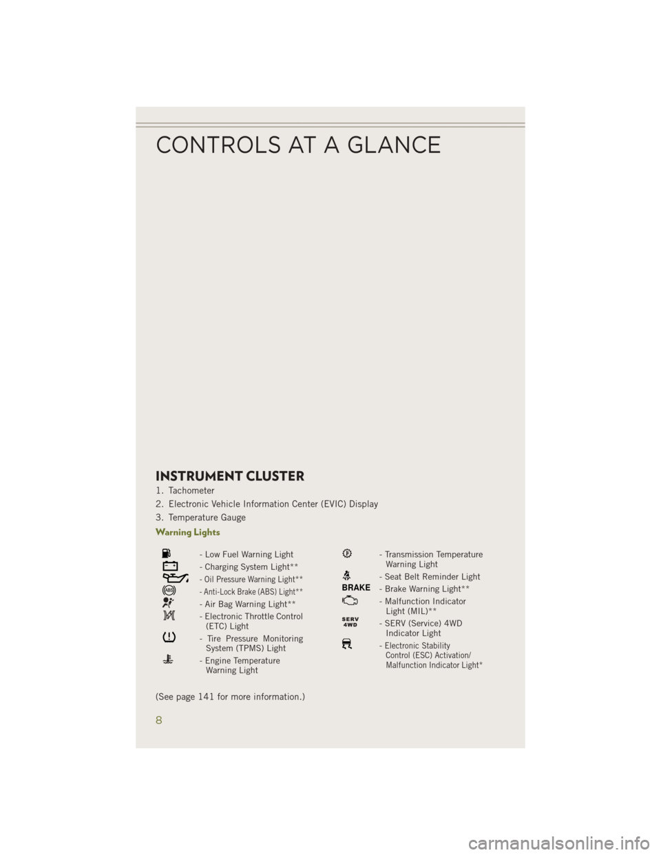
INSTRUMENT CLUSTER
1. Tachometer
2. Electronic Vehicle Information Center (EVIC) Display
3. Temperature Gauge
Warning Lights
- Low Fuel Warning Light
- Charging System Light**
- Oil Pressure Warning Light**
- Anti-Lock Brake (ABS) Light**
- Air Bag Warning Light**
- Electronic Throttle Control(ETC) Light
- Tire Pressure MonitoringSystem (TPMS) Light
- Engine TemperatureWarning Light
- Transmission TemperatureWarning Light
- Seat Belt Reminder Light
BRAKE- Brake Warning Light**
- Malfunction IndicatorLight (MIL)**
- SERV (Service) 4WDIndicator Light
-Electronic StabilityControl (ESC) Activation/
Malfunction Indicator Light*
(See page 141 for more information.)
CONTROLS AT A GLANCE
8
Page 11 of 204
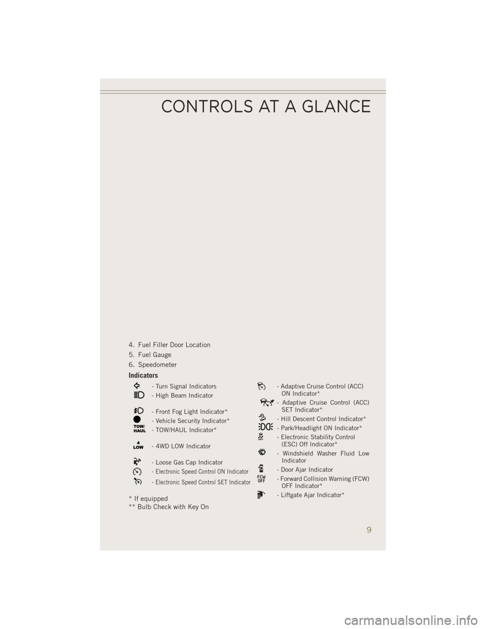
4. Fuel Filler Door Location
5. Fuel Gauge
6. Speedometer
Indicators
- Turn Signal Indicators- Adaptive Cruise Control (ACC)ON Indicator*
- High Beam Indicator- Adaptive Cruise Control (ACC)SET Indicator*
- Front Fog Light Indicator*- Hill Descent Control Indicator*- Vehicle Security Indicator*- Park/Headlight ON Indicator*- TOW/HAUL Indicator*- Electronic Stability Control(ESC) Off Indicator*
- 4WD LOW Indicator- Windshield Washer Fluid LowIndicator
- Loose Gas Cap Indicator- Door Ajar Indicator-Electronic Speed Control ON Indicator- Forward Collision Warning (FCW)OFF Indicator*-Electronic Speed Control SET Indicator
- Liftgate Ajar Indicator** If equipped
** Bulb Check with Key On
CONTROLS AT A GLANCE
9
Page 21 of 204
SUPPLEMENTAL RESTRAINT SYSTEM (SRS) — AIR BAGS
• This vehicle has Advanced Front Air Bags for both the driver and front passengeras a supplement to the seat belt restraint systems. The driver's Advanced Front Air
Bag is mounted in the center of the steering wheel. The passenger's Advanced
Front Air Bag is mounted in the instrument panel, above the glove compartment.
The words SRS AIRBAG are embossed on the air bag covers. In addition, the
vehicle is equipped with a Supplemental Driver Side Knee Air Bag mounted in the
instrument panel below the steering column and a Supplemental Passenger Side
Knee Air Bag mounted in the instrument panel below the glove compartment.
NOTE:
The Driver and Front Passenger Advanced Front Air Bags are certified to the new
Federal regulations for Advanced Air Bags.
• The Advanced Front Air Bags have a multistage inflator design. This allows the air bag to have different rates of inflation based on several factors, including the
severity and type of collision.
• This vehicle may be equipped with driver and/or front passenger seat track position sensors that may adjust the inflation rate of the Advanced Front Air Bags
based upon seat position.
•
If the Air Bag Warning Lightis not on during starting, stays on, or turns on while
driving, have the vehicle serviced by an authorized service dealer immediately.
•This vehicle may be equipped with a driver and/or front passenger seat belt buckle
switch that detects whether the driver or front passenger seat belt is fastened. The
seat belt buckle switch may adjust the inflation rate of the Advanced Front Air Bags.
• This vehicle is equipped with Supplemental Side Air Bag Inflatable Curtains (SABIC) to protect the driver, front, and rear passengers sitting next to a window.
The SABIC air bags, are located above the side windows and their covers are also
labeled: SRS AIRBAG.
• This vehicle is equipped with Supplemental Seat-Mounted Side Air Bags (SAB) to provide enhanced protection for an occupant during a side impact. The Supple-
mental Seat-Mounted Side Air Bags are located in the outboard side of the front
and rear seats.
• This vehicle may be equipped with a front passenger Occupant Classification System (OCS) that may adjust the inflation rate of the Advanced Front Air Bags
based upon occupant weight.
NOTE: • Air Bag covers may not be obvious in the interior trim, but they will open duringair bag deployment.
• After any collision, the vehicle should be taken to an authorized dealer immediately.
• Refer to the Owner's Manual on the DVD for further details regarding the Supplemental Restraint System (SRS).
GETTING STARTED
19
Page 47 of 204
Air Recirculation
• Use Recirculation for maximum A/C operation.
• For window defogging, turn the Recirculation button off.
• If the Recirculation button is pushed while in the AUTO mode, the indicator lightmay flash three times to indicate the cabin air is being controlled automatically.
Heated Mirrors
The mirrors are heated to melt frost or ice. This feature is activated whenever you turn
on the rear window defroster.
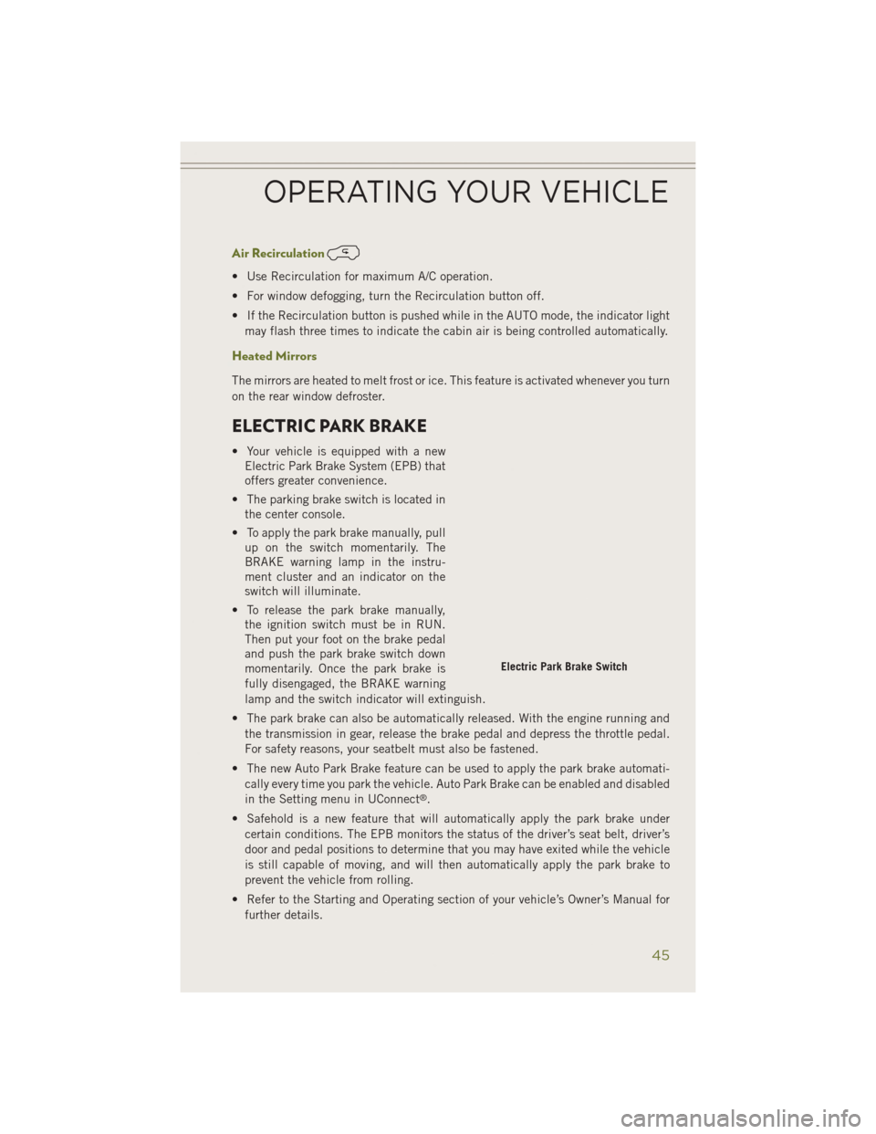
ELECTRIC PARK BRAKE
• Your vehicle is equipped with a newElectric Park Brake System (EPB) that
offers greater convenience.
• The parking brake switch is located in the center console.
• To apply the park brake manually, pull up on the switch momentarily. The
BRAKE warning lamp in the instru-
ment cluster and an indicator on the
switch will illuminate.
• To release the park brake manually, the ignition switch must be in RUN.
Then put your foot on the brake pedal
and push the park brake switch down
momentarily. Once the park brake is
fully disengaged, the BRAKE warning
lamp and the switch indicator will extinguish.
• The park brake can also be automatically released. With the engine running and the transmission in gear, release the brake pedal and depress the throttle pedal.
For safety reasons, your seatbelt must also be fastened.
• The new Auto Park Brake feature can be used to apply the park brake automati- cally every time you park the vehicle. Auto Park Brake can be enabled and disabled
in the Setting menu in UConnect
®.
• Safehold is a new feature that will automatically apply the park brake under certain conditions. The EPB monitors the status of the driver’s seat belt, driver’s
door and pedal positions to determine that you may have exited while the vehicle
is still capable of moving, and will then automatically apply the park brake to
prevent the vehicle from rolling.
• Refer to the Starting and Operating section of your vehicle’s Owner’s Manual for further details.
Electric Park Brake Switch
OPERATING YOUR VEHICLE
45
Page 127 of 204
Using HomeLink®
To operate, press and release the programmed HomeLink®button. Activation will
now occur for the programmed device (i.e., garage door opener, gate operator,
security system, entry door lock, home/office lighting, etc.,). The hand-held trans-
mitter of the device may also be used at any time.
WARNING!
• Your motorized door or gate will open and close while you are programming the universal transceiver. Do not program the transceiver if people or pets are in the
path of the door or gate.
• Do not run your vehicle in a closed garage or confined area while programming
the transceiver. Exhaust gas from your vehicle contains Carbon Monoxide (CO)
which is odorless and colorless. Carbon Monoxide is poisonous when inhaled
and can cause you and others to be severely injured or killed.
POWER INVERTER
• There is a 115 Volt, 150 Watt powerinverter outlet located on the back of
the center console. This outlet can
power cellular phones, electronics and
other low power devices requiring
power up to 150 Watts.
NOTE:
The power inverter is designed with
built-in overload protection. If the power
rating of 150 Watts is exceeded, the power
inverter will automatically shut down.
Once the electrical device has been re-
moved from the outlet, the inverter should
automatically reset. If the power rating
exceeds approximately 170 Watts, the
power inverter may have to be reset manually. To reset the inverter manually, unplug the
device and plug it in again. To avoid overloading the circuit, check the power ratings on
electrical devices prior to using the inverter.
WARNING!
To Avoid Serious Injury or Death DO NOT:
• insert any objects into the receptacles
• touch with wet hands
Close the lid when not in use. If this outlet is mishandled, it may cause an electric
shock and failure.
ELECTRONICS
125
Page 141 of 204
CAUTION!
It is necessary to follow these steps to be certain that the power transfer unit is fully
in NEUTRAL (N) before recreational towing to prevent damage to internal parts.
WARNING!
You or others could be seriously or fatally injured if you leave the vehicle
unattended with the power transfer unit in the NEUTRAL (N) position without first
fully engaging the parking brake. The NEUTRAL (N) position disengages both the
front and rear driveshafts from the powertrain and will allow the vehicle to move,
even if the transmission is in PARK. The parking brake should always be applied
when the driver is not in the vehicle.
Shifting Out of NEUTRAL (N)
Use the following procedure to prepare your vehicle for normal usage.
1. Bring the vehicle to a complete stop, leaving it connected to the tow vehicle.
2. Apply the parking brake.
3. Turn the ignition switch to the ON/RUN position, but do not start the engine.
4. Press and hold the brake pedal.
5. Shift the transmission into NEUTRAL.
6. Using a ballpoint pen or similar object, press and hold the recessed PowerTransfer Unit NEUTRAL (N) button (located by the selector switch) for one
second.
7. When the NEUTRAL (N) indicator light turns off, release the NEUTRAL (N) button.
8. After the NEUTRAL (N) button has been released, the Power Transfer Unit will shift to the position indicated by the selector switch.
9. Shift the transmission into PARK.
10. Release the brake pedal.
UTILITY
139
Page 143 of 204
ROADSIDE ASSISTANCE
Dial toll-free 1-800-521-2779 for U.S. Residents or 1-800-363-4869 for Canadian
Residents.
• Provide your name, vehicle identification number, license plate number, and yourlocation, including the telephone number from which you are calling.
• Briefly describe the nature of the problem and answer a few simple questions.
• You will be given the name of the service provider and an estimated time of arrival. If you feel you are in an “unsafe situation”, please let us know. With your consent,
we will contact local police or safety authorities.
INSTRUMENT CLUSTER WARNING LIGHTS
- Charging System Light
This light shows the status of the electrical charging system. If the charging system
light remains on, it means that the vehicle is experiencing a problem with the
charging system.
We recommend you do not continue driving if the charging system light is on. Have
the vehicle serviced immediately.
- Oil Pressure Warning Light
This light indicates low engine oil pressure. If the light turns on while driving, stop
the vehicle and shut off the engine as soon as possible. A chime will sound for four
minutes when this light turns on.
We recommend you do not operate the vehicle or engine damage will occur. Have the
vehicle serviced immediately.
- Anti-Lock Brake (ABS) Light
This light monitors the Anti-Lock Brake System (ABS). The light will turn on when the
ignition switch is turned to the ON/RUN position and may stay on for as long as four
seconds.
If the ABS light remains on or turns on while driving, it indicates that the Anti-Lock
portion of the brake system is not functioning and that service is required. However,
the conventional brake system will continue to operate normally if the BRAKE
warning light is not on.
If the ABS light is on, the brake system should be serviced as soon as possible to
restore the benefits of Anti-Lock brakes. If the ABS light does not turn on when the
ignition switch is turned to the ON/RUN position, have the light inspected by an
authorized dealer.
WHAT TO DO IN EMERGENCIES
141
Page 144 of 204
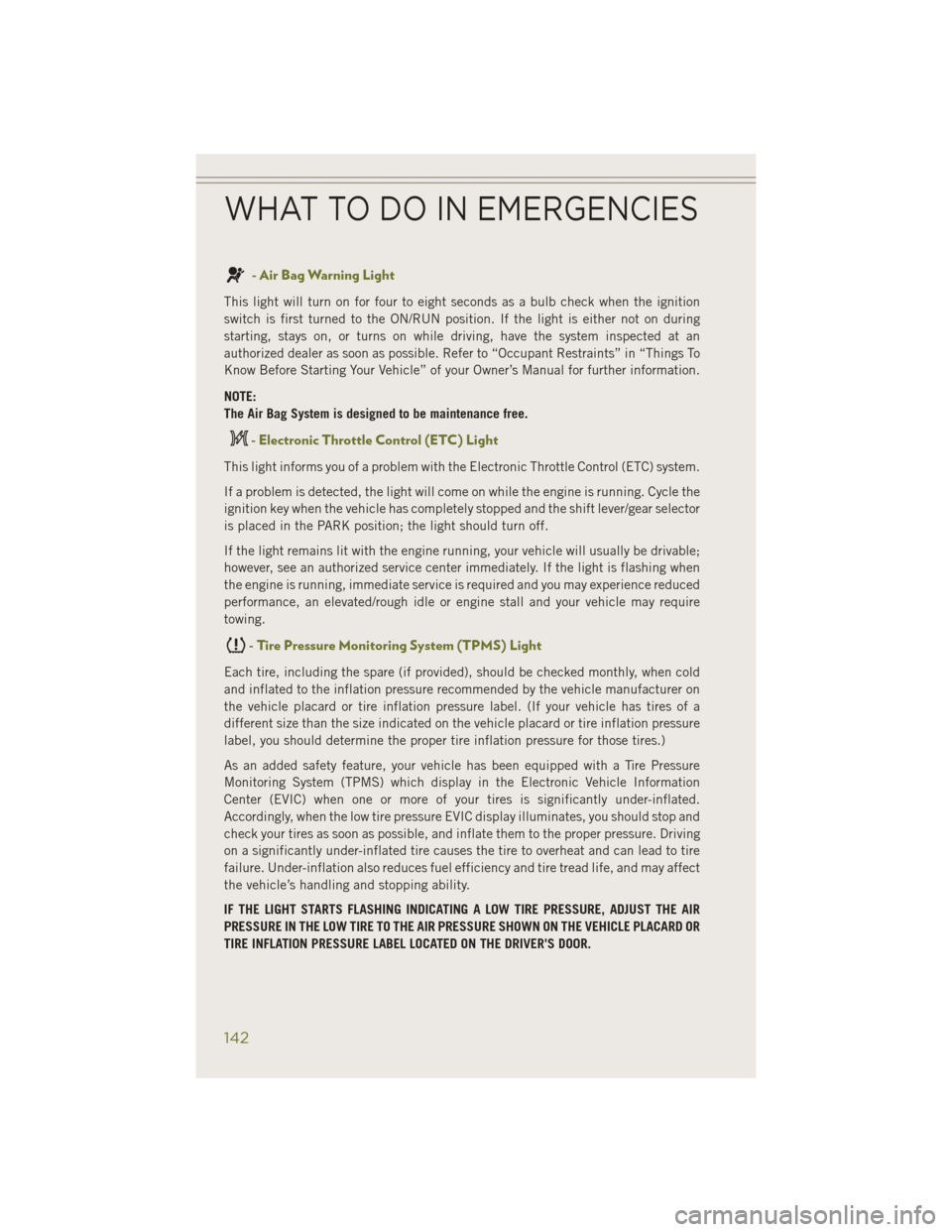
- Air Bag Warning Light
This light will turn on for four to eight seconds as a bulb check when the ignition
switch is first turned to the ON/RUN position. If the light is either not on during
starting, stays on, or turns on while driving, have the system inspected at an
authorized dealer as soon as possible. Refer to “Occupant Restraints” in “Things To
Know Before Starting Your Vehicle” of your Owner’s Manual for further information.
NOTE:
The Air Bag System is designed to be maintenance free.
- Electronic Throttle Control (ETC) Light
This light informs you of a problem with the Electronic Throttle Control (ETC) system.
If a problem is detected, the light will come on while the engine is running. Cycle the
ignition key when the vehicle has completely stopped and the shift lever/gear selector
is placed in the PARK position; the light should turn off.
If the light remains lit with the engine running, your vehicle will usually be drivable;
however, see an authorized service center immediately. If the light is flashing when
the engine is running, immediate service is required and you may experience reduced
performance, an elevated/rough idle or engine stall and your vehicle may require
towing.
- Tire Pressure Monitoring System (TPMS) Light
Each tire, including the spare (if provided), should be checked monthly, when cold
and inflated to the inflation pressure recommended by the vehicle manufacturer on
the vehicle placard or tire inflation pressure label. (If your vehicle has tires of a
different size than the size indicated on the vehicle placard or tire inflation pressure
label, you should determine the proper tire inflation pressure for those tires.)
As an added safety feature, your vehicle has been equipped with a Tire Pressure
Monitoring System (TPMS) which display in the Electronic Vehicle Information
Center (EVIC) when one or more of your tires is significantly under-inflated.
Accordingly, when the low tire pressure EVIC display illuminates, you should stop and
check your tires as soon as possible, and inflate them to the proper pressure. Driving
on a significantly under-inflated tire causes the tire to overheat and can lead to tire
failure. Under-inflation also reduces fuel efficiency and tire tread life, and may affect
the vehicle’s handling and stopping ability.
IF THE LIGHT STARTS FLASHING INDICATING A LOW TIRE PRESSURE, ADJUST THE AIR
PRESSURE IN THE LOW TIRE TO THE AIR PRESSURE SHOWN ON THE VEHICLE PLACARD OR
TIRE INFLATION PRESSURE LABEL LOCATED ON THE DRIVER'S DOOR.
WHAT TO DO IN EMERGENCIES
142
Page 145 of 204
NOTE:
After inflation, the vehicle may need to be driven for 20 minutes before the flashing light
will turn off.
Please note that the TPMS is not a substitute for proper tire maintenance, and it is
the driver’s responsibility to maintain correct tire pressure, even if under-inflation
has not reached the level to trigger illumination of the TPMS low EVIC display.
Your vehicle has also been equipped with a TPMS malfunction indicator to indicate
when the system is not operating properly. The TPMS malfunction indicator is
combined with the low tire pressure telltale. When the system detects a malfunction,
the telltale will flash for approximately one minute and then remain continuously
illuminated. This sequence will continue each time the vehicle is restarted as long as
the malfunction exists.
When the malfunction indicator is illuminated, the system may not be able to detect
or signal low tire pressure as intended. TPMS malfunctions may occur for a variety of
reasons, including the installation of replacement or alternate tires or wheels on the
vehicle that prevent the TPMS from functioning properly. Always check the TPMS
malfunction telltale after replacing one or more tires or wheels on your vehicle, to
ensure that the replacement or alternate tires and wheels allow the TPMS to continue
to function properly.
NOTE:
Tire pressures change by approximately 1 psi (7 kPa) per 12° F (7° C) of air
temperature change. Keep this in mind when checking tire pressure inside a garage,
especially in the Winter. Example: If garage temperature is 68°F (20°C) and the
outside temperature is 32°F (0°C), then the cold tire inflation pressure should be
increased by 3 psi (21 kPa), which equals 1 psi (7 kPa) for every 12°F (7°C) for this
outside temperature condition.
CAUTION!
The TPMS has been optimized for the original equipment tires and wheels. TPMS
pressures and warning have been established for the tire size equipped on your
vehicle. Undesirable system operation or sensor damage may result when using
replacement equipment that is not of the same size, type, and/or style. Aftermar-
ket wheels can cause sensor damage. Do not use tire sealant from a can, or
balance beads if your vehicle is equipped with a TPMS, as damage to the sensors
may result.
WHAT TO DO IN EMERGENCIES
143