fuel JEEP CHEROKEE 2016 KL / 5.G Owner's Manual
[x] Cancel search | Manufacturer: JEEP, Model Year: 2016, Model line: CHEROKEE, Model: JEEP CHEROKEE 2016 KL / 5.GPages: 236, PDF Size: 11.24 MB
Page 172 of 236
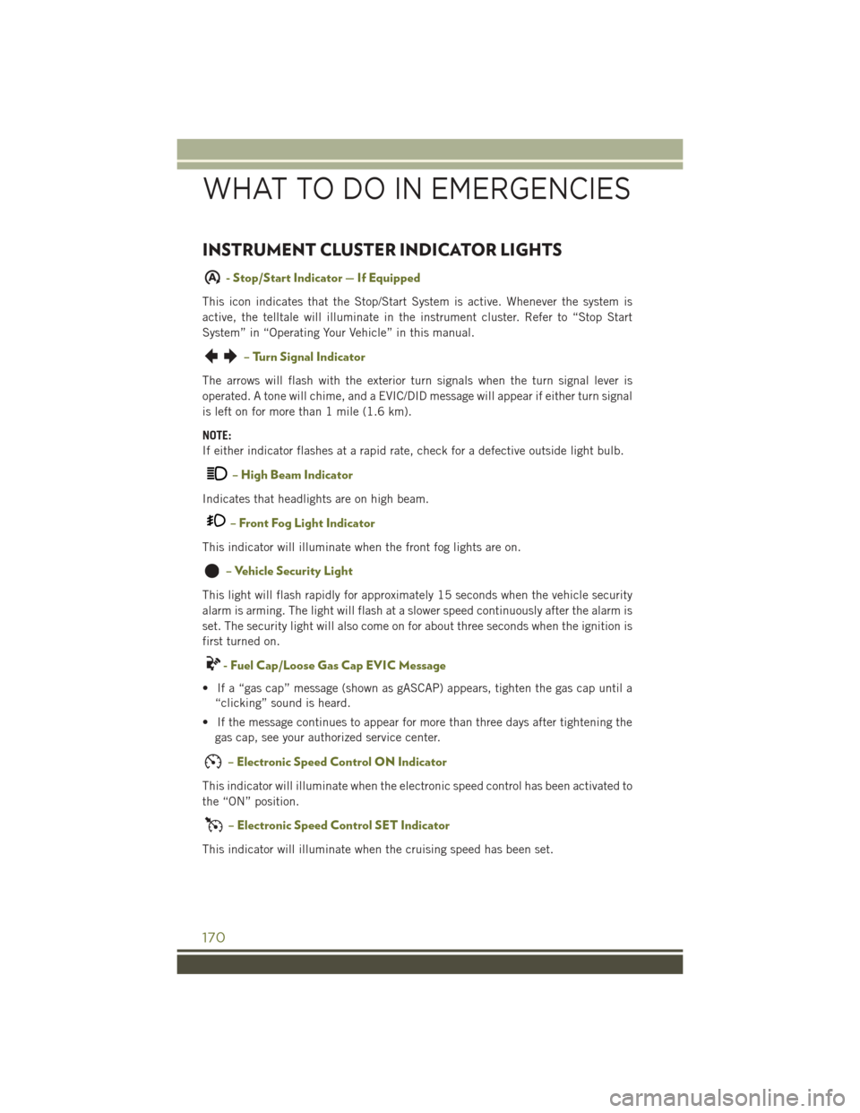
INSTRUMENT CLUSTER INDICATOR LIGHTS
A- Stop/Start Indicator — If Equipped
This icon indicates that the Stop/Start System is active. Whenever the system is
active, the telltale will illuminate in the instrument cluster. Refer to “Stop Start
System” in “Operating Your Vehicle” in this manual.
– Turn Signal Indicator
The arrows will flash with the exterior turn signals when the turn signal lever is
operated. A tone will chime, and a EVIC/DID message will appear if either turn signal
is left on for more than 1 mile (1.6 km).
NOTE:
If either indicator flashes at a rapid rate, check for a defective outside light bulb.
– High Beam Indicator
Indicates that headlights are on high beam.
– Front Fog Light Indicator
This indicator will illuminate when the front fog lights are on.
– Vehicle Security Light
This light will flash rapidly for approximately 15 seconds when the vehicle security
alarm is arming. The light will flash at a slower speed continuously after the alarm is
set. The security light will also come on for about three seconds when the ignition is
first turned on.
- Fuel Cap/Loose Gas Cap EVIC Message
• If a “gas cap” message (shown as gASCAP) appears, tighten the gas cap until a“clicking” sound is heard.
• If the message continues to appear for more than three days after tightening the gas cap, see your authorized service center.
– Electronic Speed Control ON Indicator
This indicator will illuminate when the electronic speed control has been activated to
the “ON” position.
– Electronic Speed Control SET Indicator
This indicator will illuminate when the cruising speed has been set.
WHAT TO DO IN EMERGENCIES
170
Page 190 of 236
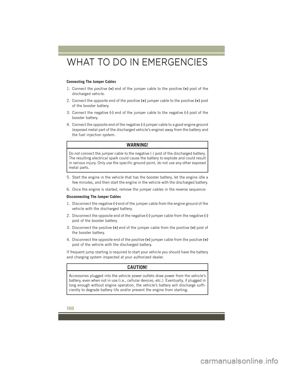
Connecting The Jumper Cables
1. Connect the positive(+)end of the jumper cable to the positive (+)post of the
discharged vehicle.
2. Connect the opposite end of the positive (+)jumper cable to the positive (+)post
of the booster battery.
3. Connect the negative (-)end of the jumper cable to the negative (-)post of the
booster battery.
4. Connect the opposite end of the negative (-)jumper cable to a good engine ground
(exposed metal part of the discharged vehicle’s engine) away from the battery and
the fuel injection system.
WARNING!
Do not connect the jumper cable to the negative (-) post of the discharged battery.
The resulting electrical spark could cause the battery to explode and could result
in serious injury. Only use the specific ground point, do not use any other exposed
metal parts.
5. Start the engine in the vehicle that has the booster battery, let the engine idle a few minutes, and then start the engine in the vehicle with the discharged battery.
6. Once the engine is started, remove the jumper cables in the reverse sequence:
Disconnecting The Jumper Cables
1. Disconnect the negative (-)end of the jumper cable from the engine ground of the
vehicle with the discharged battery.
2. Disconnect the opposite end of the negative (-)jumper cable from the negative (-)
post of the booster battery.
3. Disconnect the positive (+)end of the jumper cable from the positive (+)post of
the booster battery.
4. Disconnect the opposite end of the positive (+)jumper cable from the positive (+)
post of the vehicle with the discharged battery.
If frequent jump starting is required to start your vehicle you should have the battery
and charging system inspected at your authorized dealer.
CAUTION!
Accessories plugged into the vehicle power outlets draw power from the vehicle’s
battery, even when not in use (i.e., cellular devices, etc.). Eventually, if plugged in
long enough without engine operation, the vehicle’s battery will discharge suffi-
ciently to degrade battery life and/or prevent the engine from starting.
WHAT TO DO IN EMERGENCIES
188
Page 200 of 236
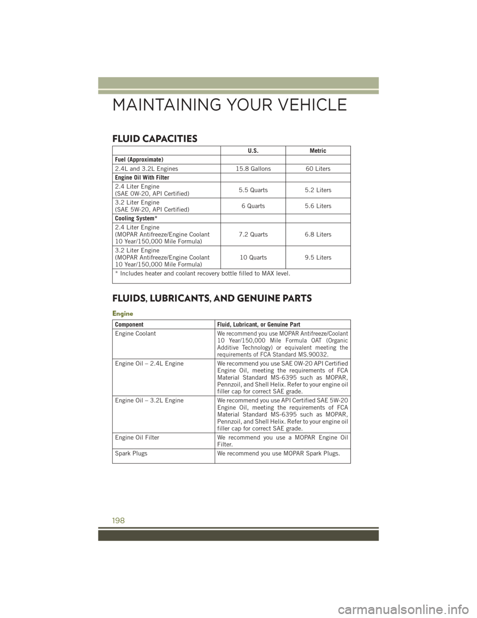
FLUID CAPACITIES
U.S.Metric
Fuel (Approximate)
2.4L and 3.2L Engines 15.8 Gallons60 Liters
Engine Oil With Filter
2.4 Liter Engine
(SAE 0W-20, API Certified) 5.5 Quarts
5.2 Liters
3.2 Liter Engine
(SAE 5W-20, API Certified) 6 Quarts
5.6 Liters
Cooling System*
2.4 Liter Engine
(MOPAR Antifreeze/Engine Coolant
10 Year/150,000 Mile Formula) 7.2 Quarts
6.8 Liters
3.2 Liter Engine
(MOPAR Antifreeze/Engine Coolant
10 Year/150,000 Mile Formula) 10 Quarts
9.5 Liters
* Includes heater and coolant recovery bottle filled to MAX level.
FLUIDS, LUBRICANTS, AND GENUINE PARTS
Engine
Component Fluid, Lubricant, or Genuine Part
Engine Coolant
We recommend you use MOPAR Antifreeze/Coolant
10 Year/150,000 Mile Formula OAT (Organic
Additive Technology) or equivalent meeting the
requirements of FCA Standard MS.90032.
Engine Oil – 2.4L Engine We recommend you use SAE 0W-20 API Certified
Engine Oil, meeting the requirements of FCA
Material Standard MS-6395 such as MOPAR,
Pennzoil, and Shell Helix. Refer to your engine oil
filler cap for correct SAE grade.
Engine Oil – 3.2L Engine We recommend you use API Certified SAE 5W-20
Engine Oil, meeting the requirements of FCA
Material Standard MS-6395 such as MOPAR,
Pennzoil, and Shell Helix. Refer to your engine oil
filler cap for correct SAE grade.
Engine Oil Filter We recommend you use a MOPAR Engine Oil
Filter.
Spark Plugs We recommend you use MOPAR Spark Plugs.
MAINTAINING YOUR VEHICLE
198
Page 201 of 236
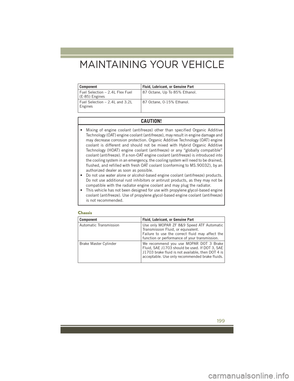
ComponentFluid, Lubricant, or Genuine Part
Fuel Selection – 2.4L Flex Fuel
(E-85) Engines 87 Octane, Up To 85% Ethanol.
Fuel Selection – 2.4L and 3.2L
Engines 87 Octane, 0-15% Ethanol.
CAUTION!
• Mixing of engine coolant (antifreeze) other than specified Organic Additive
Technology (OAT) engine coolant (antifreeze), may result in engine damage and
may decrease corrosion protection. Organic Additive Technology (OAT) engine
coolant is different and should not be mixed with Hybrid Organic Additive
Technology (HOAT) engine coolant (antifreeze) or any “globally compatible”
coolant (antifreeze). If a non-OAT engine coolant (antifreeze) is introduced into
the cooling system in an emergency, the cooling system will need to be drained,
flushed, and refilled with fresh OAT coolant (conforming to MS.90032), by an
authorized dealer as soon as possible.
• Do not use water alone or alcohol-based engine coolant (antifreeze) products.
Do not use additional rust inhibitors or antirust products, as they may not be
compatible with the radiator engine coolant and may plug the radiator.
• This vehicle has not been designed for use with propylene glycol-based engine
coolant (antifreeze). Use of propylene glycol-based engine coolant (antifreeze)
is not recommended.
Chassis
Component Fluid, Lubricant, or Genuine Part
Automatic Transmission Use only MOPAR ZF 8&9 Speed ATF Automatic
Transmission Fluid, or equivalent.
Failure to use the correct fluid may affect the
function or performance of your transmission.
Brake Master Cylinder We recommend you use MOPAR DOT 3 Brake
Fluid, SAE J1703 should be used. If DOT 3, SAE
J1703 brake fluid is not available, then DOT 4 is
acceptable. Use only recommended brake fluids.
MAINTAINING YOUR VEHICLE
199
Page 202 of 236
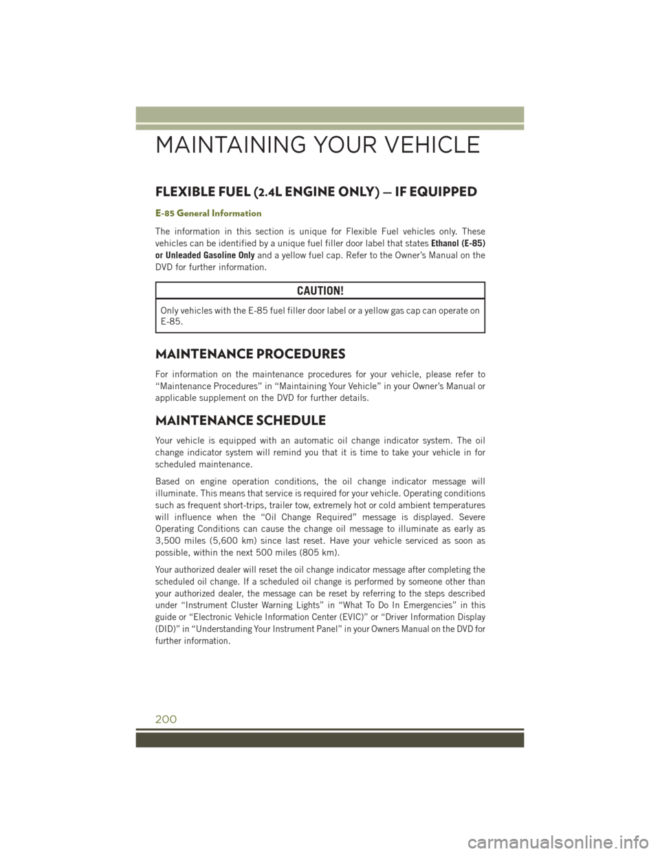
FLEXIBLE FUEL (2.4L ENGINE ONLY) — IF EQUIPPED
E-85 General Information
The information in this section is unique for Flexible Fuel vehicles only. These
vehicles can be identified by a unique fuel filler door label that statesEthanol (E-85)
or Unleaded Gasoline Only and a yellow fuel cap. Refer to the Owner’s Manual on the
DVD for further information.
CAUTION!
Only vehicles with the E-85 fuel filler door label or a yellow gas cap can operate on
E-85.
MAINTENANCE PROCEDURES
For information on the maintenance procedures for your vehicle, please refer to
“Maintenance Procedures” in “Maintaining Your Vehicle” in your Owner’s Manual or
applicable supplement on the DVD for further details.
MAINTENANCE SCHEDULE
Your vehicle is equipped with an automatic oil change indicator system. The oil
change indicator system will remind you that it is time to take your vehicle in for
scheduled maintenance.
Based on engine operation conditions, the oil change indicator message will
illuminate. This means that service is required for your vehicle. Operating conditions
such as frequent short-trips, trailer tow, extremely hot or cold ambient temperatures
will influence when the “Oil Change Required” message is displayed. Severe
Operating Conditions can cause the change oil message to illuminate as early as
3,500 miles (5,600 km) since last reset. Have your vehicle serviced as soon as
possible, within the next 500 miles (805 km).
Your authorized dealer will reset the oil change indicator message after completing the
scheduled oil change. If a scheduled oil change is performed by someone other than
your authorized dealer, the message can be reset by referring to the steps described
under “Instrument Cluster Warning Lights” in “What To Do In Emergencies” in this
guide or “Electronic Vehicle Information Center (EVIC)” or “Driver Information Display
(DID)” in “Understanding Your Instrument Panel” in your Owners Manual on the DVD for
further information.
MAINTAINING YOUR VEHICLE
200
Page 206 of 236
FUSES
WARNING!
• When replacing a blown fuse, always use an appropriate replacement fuse withthe same amp rating as the original fuse. Never replace a fuse with another
fuse of higher amp rating. Never replace a blown fuse with metal wires or any
other material. Failure to use proper fuses may result in serious personal injury,
fire and/or property damage.
• Before replacing a fuse, make sure that the ignition is off and that all the other
services are switched off and/or disengaged.
• If the replaced fuse blows again, contact an authorized dealer.
• If a general protection fuse for safety systems (air bag system, braking system),
power unit systems (engine system, gearbox system) or steering system blows,
contact an authorized dealer.
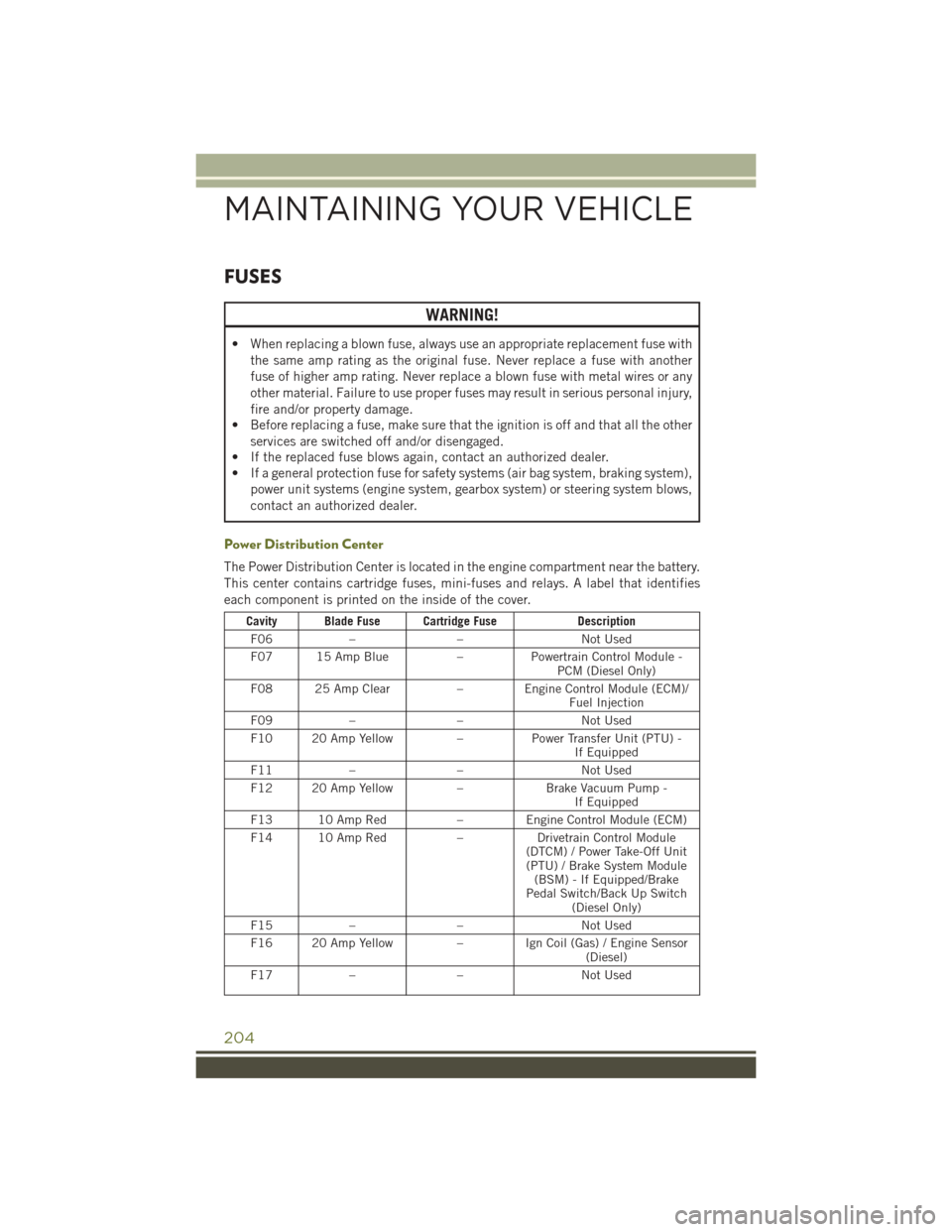
Power Distribution Center
The Power Distribution Center is located in the engine compartment near the battery.
This center contains cartridge fuses, mini-fuses and relays. A label that identifies
each component is printed on the inside of the cover.
Cavity Blade Fuse Cartridge Fuse Description
F06 – – Not Used
F07 15 Amp Blue –Powertrain Control Module -
PCM (Diesel Only)
F08 25 Amp Clear – Engine Control Module (ECM)/
Fuel Injection
F09 – – Not Used
F10 20 Amp Yellow –Power Transfer Unit (PTU) -
If Equipped
F11 – – Not Used
F12 20 Amp Yellow –Brake Vacuum Pump -
If Equipped
F13 10 Amp Red –Engine Control Module (ECM)
F14 10 Amp Red –Drivetrain Control Module
(DTCM) / Power Take-Off Unit (PTU) / Brake System Module (BSM) - If Equipped/Brake
Pedal Switch/Back Up Switch (Diesel Only)
F15 – – Not Used
F16 20 Amp Yellow –Ign Coil (Gas) / Engine Sensor
(Diesel)
F17 – – Not Used
MAINTAINING YOUR VEHICLE
204
Page 207 of 236
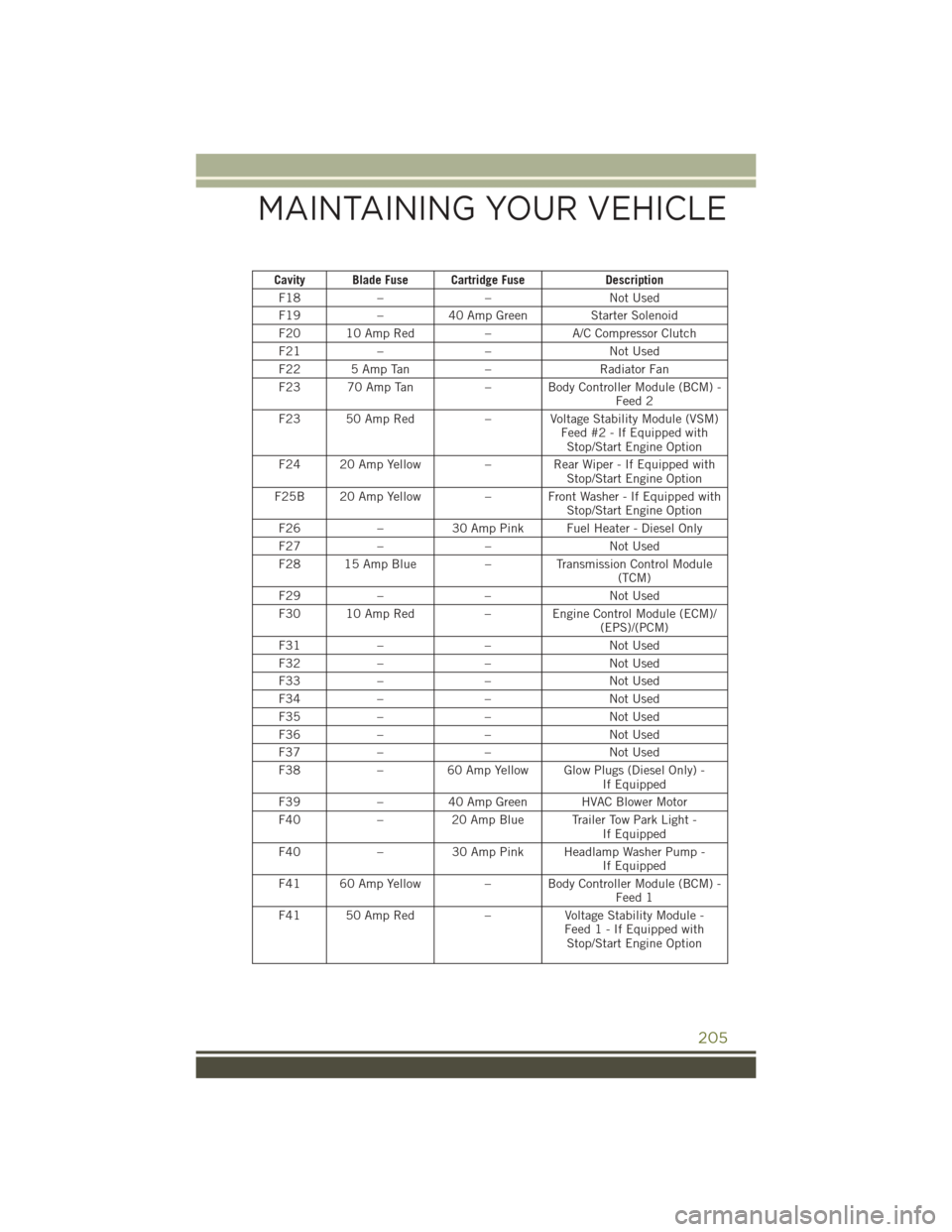
Cavity Blade Fuse Cartridge FuseDescription
F18 – – Not Used
F19 –40 Amp Green Starter Solenoid
F20 10 Amp Red –A/C Compressor Clutch
F21 – – Not Used
F22 5 Amp Tan –Radiator Fan
F23 70 Amp Tan – Body Controller Module (BCM) -
Feed 2
F23 50 Amp Red – Voltage Stability Module (VSM)
Feed #2 - If Equipped withStop/Start Engine Option
F24 20 Amp Yellow –Rear Wiper - If Equipped with
Stop/Start Engine Option
F25B 20 Amp Yellow – Front Washer - If Equipped with
Stop/Start Engine Option
F26 –30 Amp Pink Fuel Heater - Diesel Only
F27 – – Not Used
F28 15 Amp Blue –Transmission Control Module
(TCM)
F29 – – Not Used
F30 10 Amp Red – Engine Control Module (ECM)/
(EPS)/(PCM)
F31 – – Not Used
F32 – – Not Used
F33 – – Not Used
F34 – – Not Used
F35 – – Not Used
F36 – – Not Used
F37 – – Not Used
F38 –60 Amp Yellow Glow Plugs (Diesel Only) -
If Equipped
F39 –40 Amp Green HVAC Blower Motor
F40 –20 Amp Blue Trailer Tow Park Light -
If Equipped
F40 –30 Amp Pink Headlamp Washer Pump -
If Equipped
F41 60 Amp Yellow – Body Controller Module (BCM) -
Feed 1
F41 50 Amp Red –Voltage Stability Module -
Feed 1 - If Equipped with Stop/Start Engine Option
MAINTAINING YOUR VEHICLE
205
Page 208 of 236
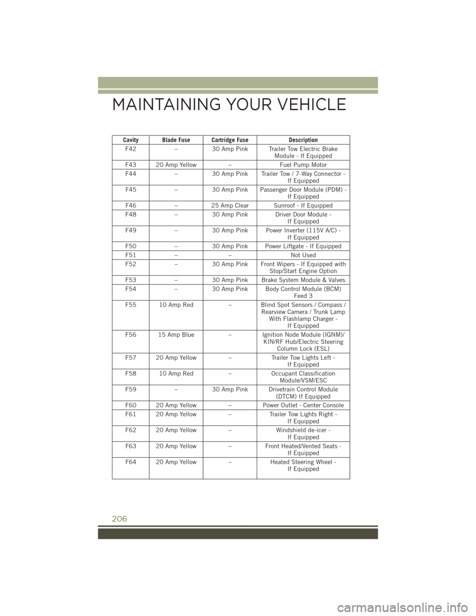
Cavity Blade Fuse Cartridge FuseDescription
F42 –30 Amp Pink Trailer Tow Electric Brake
Module - If Equipped
F43 20 Amp Yellow –Fuel Pump Motor
F44 –30 Amp Pink Trailer Tow / 7-Way Connector -
If Equipped
F45 –30 Amp Pink Passenger Door Module (PDM) -
If Equipped
F46 –25 Amp Clear Sunroof - If Equipped
F48 –30 Amp Pink Driver Door Module -
If Equipped
F49 –30 Amp Pink Power Inverter (115V A/C) -
If Equipped
F50 –30 Amp Pink Power Liftgate - If Equipped
F51 – – Not Used
F52 –30 Amp Pink Front Wipers - If Equipped with
Stop/Start Engine Option
F53 –30 Amp Pink Brake System Module & Valves
F54 –30 Amp Pink Body Control Module (BCM)
Feed 3
F55 10 Amp Red – Blind Spot Sensors / Compass /
Rearview Camera / Trunk LampWith Flashlamp Charger - If Equipped
F56 15 Amp Blue – Ignition Node Module (IGNM)/
KIN/RF Hub/Electric SteeringColumn Lock (ESL)
F57 20 Amp Yellow –Trailer Tow Lights Left -
If Equipped
F58 10 Amp Red –Occupant Classification
Module/VSM/ESC
F59 –30 Amp Pink Drivetrain Control Module
(DTCM) If Equipped
F60 20 Amp Yellow –Power Outlet - Center Console
F61 20 Amp Yellow –Trailer Tow Lights Right -
If Equipped
F62 20 Amp Yellow –Windshield de-icer -
If Equipped
F63 20 Amp Yellow –Front Heated/Vented Seats -
If Equipped
F64 20 Amp Yellow –Heated Steering Wheel -
If Equipped
MAINTAINING YOUR VEHICLE
206
Page 209 of 236
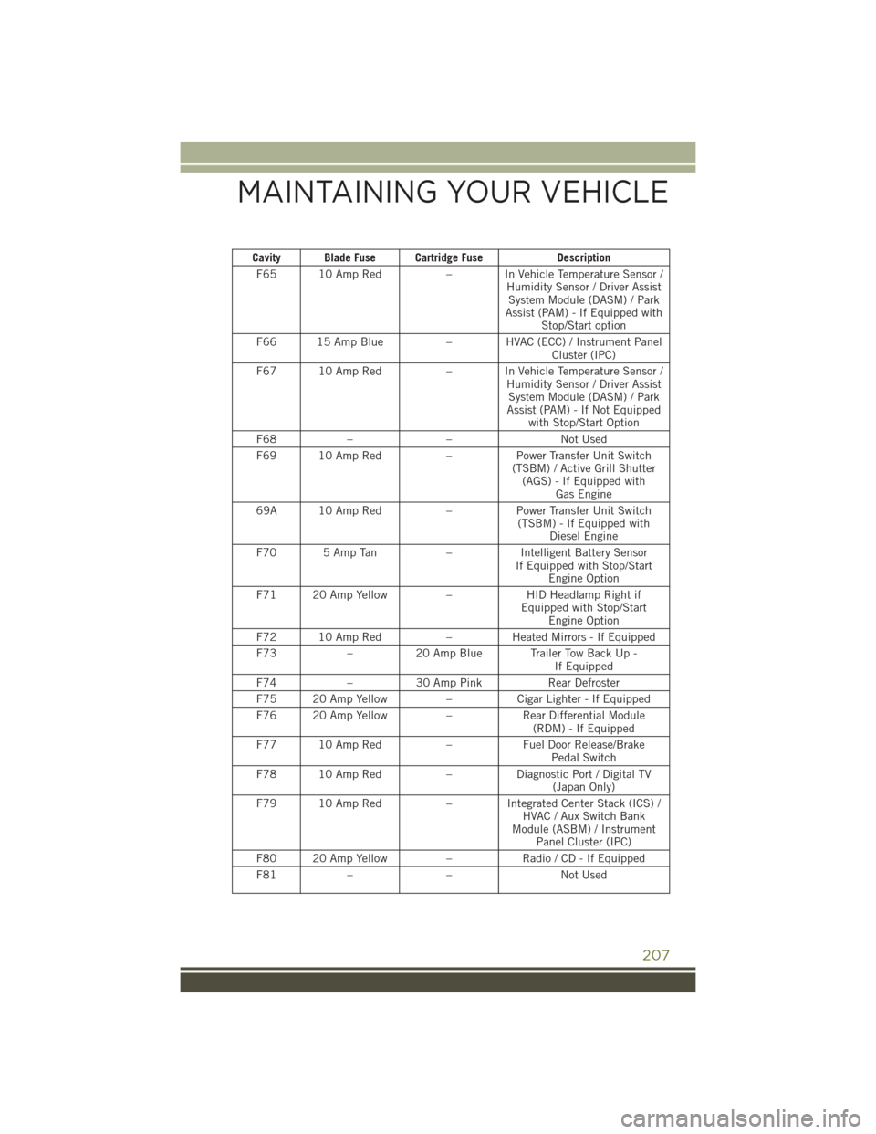
Cavity Blade Fuse Cartridge FuseDescription
F65 10 Amp Red – In Vehicle Temperature Sensor /
Humidity Sensor / Driver AssistSystem Module (DASM) / Park
Assist (PAM) - If Equipped with Stop/Start option
F66 15 Amp Blue – HVAC (ECC) / Instrument Panel
Cluster (IPC)
F67 10 Amp Red – In Vehicle Temperature Sensor /
Humidity Sensor / Driver AssistSystem Module (DASM) / Park
Assist (PAM) - If Not Equipped with Stop/Start Option
F68 – – Not Used
F69 10 Amp Red –Power Transfer Unit Switch
(TSBM) / Active Grill Shutter (AGS) - If Equipped with Gas Engine
69A 10 Amp Red –Power Transfer Unit Switch
(TSBM) - If Equipped with Diesel Engine
F70 5 Amp Tan –Intelligent Battery Sensor
If Equipped with Stop/Start Engine Option
F71 20 Amp Yellow –HID Headlamp Right if
Equipped with Stop/Start Engine Option
F72 10 Amp Red –Heated Mirrors - If Equipped
F73 –20 Amp Blue Trailer Tow Back Up -
If Equipped
F74 –30 Amp Pink Rear Defroster
F75 20 Amp Yellow –Cigar Lighter - If Equipped
F76 20 Amp Yellow –Rear Differential Module
(RDM) - If Equipped
F77 10 Amp Red –Fuel Door Release/Brake
Pedal Switch
F78 10 Amp Red –Diagnostic Port / Digital TV
(Japan Only)
F79 10 Amp Red – Integrated Center Stack (ICS) /
HVAC / Aux Switch Bank
Module (ASBM) / Instrument Panel Cluster (IPC)
F80 20 Amp Yellow –Radio / CD - If Equipped
F81 – – Not Used
MAINTAINING YOUR VEHICLE
207
Page 212 of 236
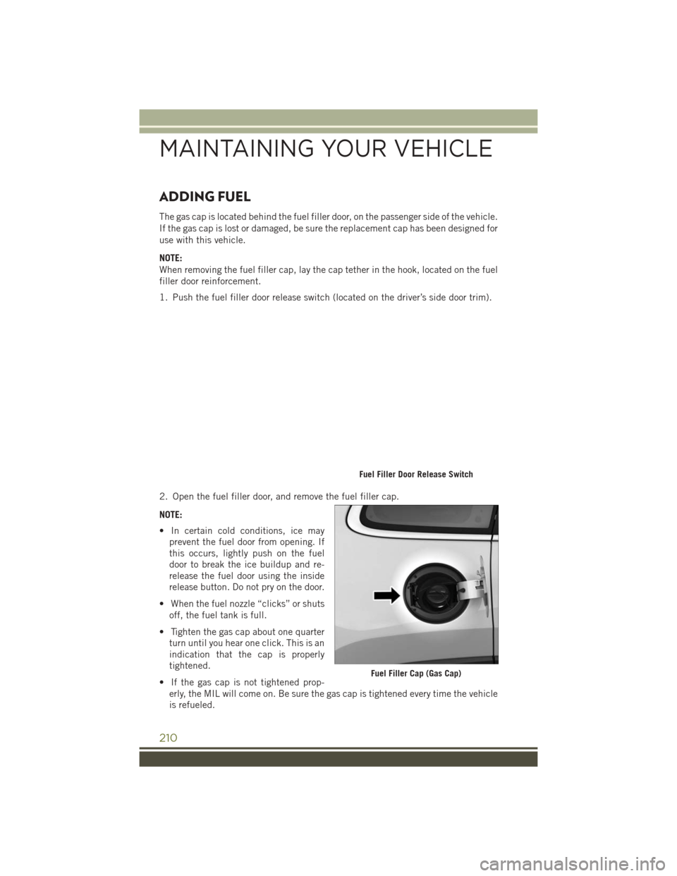
ADDING FUEL
The gas cap is located behind the fuel filler door, on the passenger side of the vehicle.
If the gas cap is lost or damaged, be sure the replacement cap has been designed for
use with this vehicle.
NOTE:
When removing the fuel filler cap, lay the cap tether in the hook, located on the fuel
filler door reinforcement.
1. Push the fuel filler door release switch (located on the driver’s side door trim).
2. Open the fuel filler door, and remove the fuel filler cap.
NOTE:
• In certain cold conditions, ice mayprevent the fuel door from opening. If
this occurs, lightly push on the fuel
door to break the ice buildup and re-
release the fuel door using the inside
release button. Do not pry on the door.
• When the fuel nozzle “clicks” or shuts off, the fuel tank is full.
• Tighten the gas cap about one quarter turn until you hear one click. This is an
indication that the cap is properly
tightened.
• If the gas cap is not tightened prop- erly, the MIL will come on. Be sure the gas cap is tightened every time the vehicle
is refueled.
Fuel Filler Door Release Switch
Fuel Filler Cap (Gas Cap)
MAINTAINING YOUR VEHICLE
210