instrument panel JEEP CHEROKEE 2016 KL / 5.G Owner's Manual
[x] Cancel search | Manufacturer: JEEP, Model Year: 2016, Model line: CHEROKEE, Model: JEEP CHEROKEE 2016 KL / 5.GPages: 236, PDF Size: 11.24 MB
Page 195 of 236
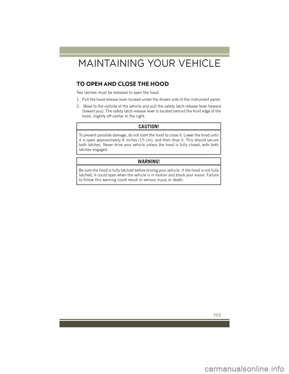
TO OPEN AND CLOSE THE HOOD
Two latches must be released to open the hood.
1. Pull the hood release lever located under the drivers side of the instrument panel.
2. Move to the outside of the vehicle and pull the safety latch release lever forward(toward you). The safety latch release lever is located behind the front edge of the
hood, slightly off-center to the right.
CAUTION!
To prevent possible damage, do not slam the hood to close it. Lower the hood until
it is open approximately 6 inches (15 cm), and then drop it. This should secure
both latches. Never drive your vehicle unless the hood is fully closed, with both
latches engaged.
WARNING!
Be sure the hood is fully latched before driving your vehicle. If the hood is not fully
latched, it could open when the vehicle is in motion and block your vision. Failure
to follow this warning could result in serious injury or death.
MAINTAINING YOUR VEHICLE
193
Page 202 of 236
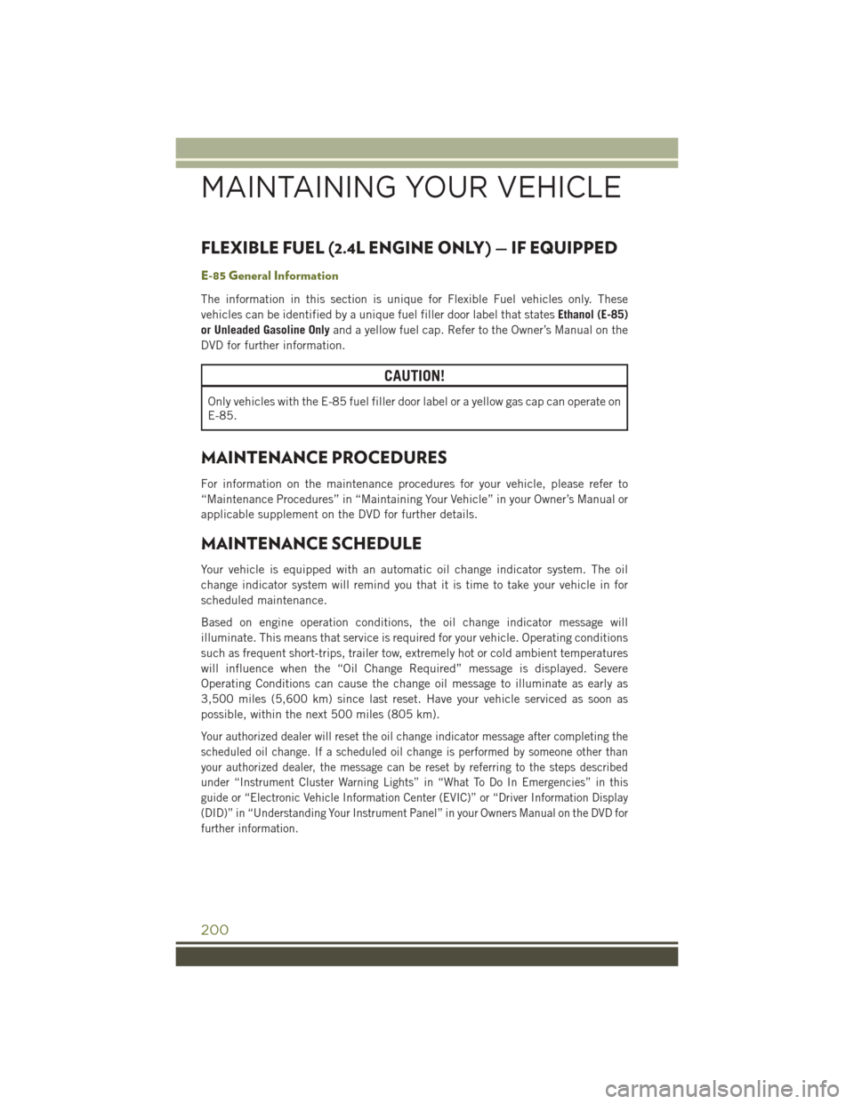
FLEXIBLE FUEL (2.4L ENGINE ONLY) — IF EQUIPPED
E-85 General Information
The information in this section is unique for Flexible Fuel vehicles only. These
vehicles can be identified by a unique fuel filler door label that statesEthanol (E-85)
or Unleaded Gasoline Only and a yellow fuel cap. Refer to the Owner’s Manual on the
DVD for further information.
CAUTION!
Only vehicles with the E-85 fuel filler door label or a yellow gas cap can operate on
E-85.
MAINTENANCE PROCEDURES
For information on the maintenance procedures for your vehicle, please refer to
“Maintenance Procedures” in “Maintaining Your Vehicle” in your Owner’s Manual or
applicable supplement on the DVD for further details.
MAINTENANCE SCHEDULE
Your vehicle is equipped with an automatic oil change indicator system. The oil
change indicator system will remind you that it is time to take your vehicle in for
scheduled maintenance.
Based on engine operation conditions, the oil change indicator message will
illuminate. This means that service is required for your vehicle. Operating conditions
such as frequent short-trips, trailer tow, extremely hot or cold ambient temperatures
will influence when the “Oil Change Required” message is displayed. Severe
Operating Conditions can cause the change oil message to illuminate as early as
3,500 miles (5,600 km) since last reset. Have your vehicle serviced as soon as
possible, within the next 500 miles (805 km).
Your authorized dealer will reset the oil change indicator message after completing the
scheduled oil change. If a scheduled oil change is performed by someone other than
your authorized dealer, the message can be reset by referring to the steps described
under “Instrument Cluster Warning Lights” in “What To Do In Emergencies” in this
guide or “Electronic Vehicle Information Center (EVIC)” or “Driver Information Display
(DID)” in “Understanding Your Instrument Panel” in your Owners Manual on the DVD for
further information.
MAINTAINING YOUR VEHICLE
200
Page 209 of 236
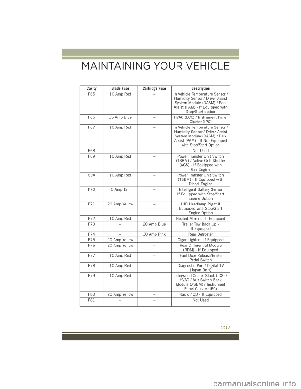
Cavity Blade Fuse Cartridge FuseDescription
F65 10 Amp Red – In Vehicle Temperature Sensor /
Humidity Sensor / Driver AssistSystem Module (DASM) / Park
Assist (PAM) - If Equipped with Stop/Start option
F66 15 Amp Blue – HVAC (ECC) / Instrument Panel
Cluster (IPC)
F67 10 Amp Red – In Vehicle Temperature Sensor /
Humidity Sensor / Driver AssistSystem Module (DASM) / Park
Assist (PAM) - If Not Equipped with Stop/Start Option
F68 – – Not Used
F69 10 Amp Red –Power Transfer Unit Switch
(TSBM) / Active Grill Shutter (AGS) - If Equipped with Gas Engine
69A 10 Amp Red –Power Transfer Unit Switch
(TSBM) - If Equipped with Diesel Engine
F70 5 Amp Tan –Intelligent Battery Sensor
If Equipped with Stop/Start Engine Option
F71 20 Amp Yellow –HID Headlamp Right if
Equipped with Stop/Start Engine Option
F72 10 Amp Red –Heated Mirrors - If Equipped
F73 –20 Amp Blue Trailer Tow Back Up -
If Equipped
F74 –30 Amp Pink Rear Defroster
F75 20 Amp Yellow –Cigar Lighter - If Equipped
F76 20 Amp Yellow –Rear Differential Module
(RDM) - If Equipped
F77 10 Amp Red –Fuel Door Release/Brake
Pedal Switch
F78 10 Amp Red –Diagnostic Port / Digital TV
(Japan Only)
F79 10 Amp Red – Integrated Center Stack (ICS) /
HVAC / Aux Switch Bank
Module (ASBM) / Instrument Panel Cluster (IPC)
F80 20 Amp Yellow –Radio / CD - If Equipped
F81 – – Not Used
MAINTAINING YOUR VEHICLE
207
Page 211 of 236
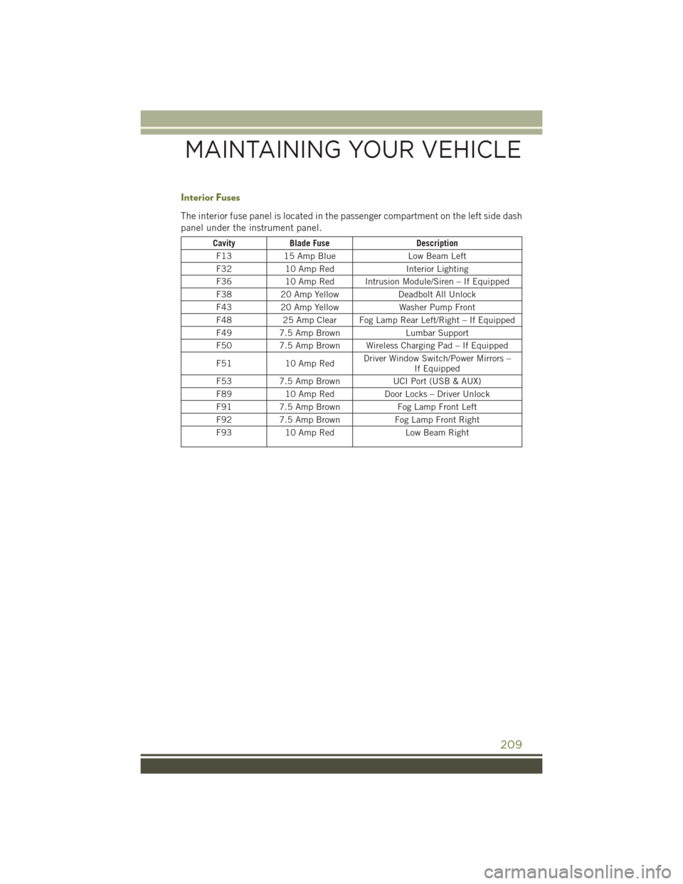
Interior Fuses
The interior fuse panel is located in the passenger compartment on the left side dash
panel under the instrument panel.
CavityBlade Fuse Description
F13 15 Amp Blue Low Beam Left
F32 10 Amp Red Interior Lighting
F36 10 Amp Red Intrusion Module/Siren – If Equipped
F38 20 Amp Yellow Deadbolt All Unlock
F43 20 Amp Yellow Washer Pump Front
F48 25 Amp Clear Fog Lamp Rear Left/Right – If Equipped
F49 7.5 Amp Brown Lumbar Support
F50 7.5 Amp Brown Wireless Charging Pad – If Equipped
F51 10 Amp Red Driver Window Switch/Power Mirrors –
If Equipped
F53 7.5 Amp Brown UCI Port (USB & AUX)
F89 10 Amp Red Door Locks – Driver Unlock
F91 7.5 Amp Brown Fog Lamp Front Left
F92 7.5 Amp Brown Fog Lamp Front Right
F93 10 Amp Red Low Beam Right
MAINTAINING YOUR VEHICLE
209
Page 213 of 236
CAUTION!
• Damage to the fuel system or emission control system could result from usingan improper fuel filler cap. A poorly fitting cap could let impurities into the fuel
system. Also, a poorly fitting aftermarket cap can cause the “Malfunction
Indicator Light (MIL)” to illuminate, due to fuel vapors escaping from the
system.
• A poorly fitting fuel filler cap may cause the MIL to turn on.
•
To avoid fuel spillage and overfilling, do not “top off” the fuel tank after filling.
WARNING!
• Never have any smoking materials lit in or near the vehicle when the gas cap is
removed or the tank is being filled.
• Never add fuel when the engine is running. This is in violation of most state and
federal fire regulations and may cause the MIL to turn on.
• A fire may result if gasoline is pumped into a portable container that is inside
of a vehicle. You could be burned. Always place gas containers on the ground
while filling.
Emergency Fuel Filler Door Release
If you are unable to open the fuel filler door, use the fuel filler door emergency
release.
1. Open the liftgate.
2. Remove access door located on right interior trim panel for release cable with the tip of your key.
3. Grab the release cable tether and pull up to release the fuel filler door.
Loose Fuel Filler Cap Message
If the vehicle diagnostic system determines that the fuel filler cap is loose,
improperly installed, or damaged, a “CHECK GASCAP” message will be displayed in
the Electronic Vehicle Information Center (EVIC) or Driver Information Display (DID).
Refer to “Electronic Vehicle Information (EVIC) or "Driver Information Display (DID)”
in “Understanding Your Instrument Panel” for further information. Tighten the fuel
filler cap until a “clicking” sound is heard. This is an indication that the fuel filler cap
is properly tightened. Refer to “Onboard Diagnostic System” in “Maintaining Your
Vehicle” for further information.
MAINTAINING YOUR VEHICLE
211
Page 224 of 236
FAQ...................219
FiltersAirCleaner ............200
EngineOil ......... 198, 200
Engine Oil Disposal .......200
Flashers TurnSignal ............170
Flash-To-Pass ..............40
Flexible Fuel Vehicles Fuel Requirements .......200
Fluid,Brake..............199
Fluid Capacities ............198
Fluids, Lubricants And Genuine Parts ................198
FogLights ............41,170
FoldingRearSeat ...........35
Forward Collision Warning .......49
Four Wheel Drive ...........156
Four Wheel Drive Operation .....153
Freeing A Stuck Vehicle .......189
Frequently Asked Questions .....219
Front And Rear ParkSense System...62
Front ParkSense System ........62
Fuel Ethanol ..............200
Filler Cap (Gas Cap) ....170, 210
Octane Rating ..........198
Specifications ..........198
Tank Capacity ..........198
Fuel, Flexible .............200
Fuses..................204
Gas Cap (Fuel Filler Cap) ......210
Gear Select Lever Override ......190
GeneralMaintenance.........200
Glass Cleaning ............200
Hands-Free Phone (Uconnect) . . .131
Headlights ................41
Automatic .............41
Cleaning .............200
Dimmer Switch ..........41
HighBeam .............40
Head Restraints ............30
HeadRests...............30
Heated Mirrors ........51,54,58
High Beam Indicator .........170 High Beam/Low Beam Select
(Dimmer) Switch ..........40
HomeLink (Garage Door Opener)...144
Hood Release .............193
Identifying Your Radio .........72
Installing A Child Restraint WithALR...............28
Installing Child Restraints Using The LATCH Lower Anchorages . . .27
Installing Child Restraints Using The Vehicle Seat Belt ........28
Instrument Cluster ............8
Instrument Cluster Warning Lights ............ 163, 170
Instrument Panel Cover .......200
Instrument Panel Lens Cleaning...200
Interior And Instrument Lights .....7
Interior Appearance Care .......200
Interior Fuses .............209
Intermittent Wipers (Delay Wipers)..42
Introduction ...............3
Canada ................4
In Vehicle Features Uconnect Access ..........79
Inverter Outlet (115V) ........147
Inverter, Power ............147
iPod/USB/MP3 Control Bluetooth Streaming Audio . . .131
Jacking Instructions .........182
Jack Location .............180
Jack Operation .........180, 182
Jump Starting .............186
KeyFob.................10 Arm The Alarm ...........12
Disarm The Alarm .........13
Keyless Enter-N-Go ...........13
KeyFob ...............13
Lock/Unlock .......13,14,15
Passive Entry ............13
Remote Control ...........13
LaneChangeAndTurnSignals....40
Lane Change Assist ..........40
LaneSense ...............64
INDEX
222