light JEEP CHEROKEE 2016 KL / 5.G Owner's Guide
[x] Cancel search | Manufacturer: JEEP, Model Year: 2016, Model line: CHEROKEE, Model: JEEP CHEROKEE 2016 KL / 5.GPages: 236, PDF Size: 11.24 MB
Page 147 of 236
Programming A Rolling Code
NOTE:
For programming Garage Door Openers that were manufactured after 1995. These
Garage Door Openers can be identified by the “LEARN” or “TRAIN” button located
where the hanging antenna is attached to the Garage Door Opener. It is NOT the
button that is normally used to open and close the door. The name and color of the
button may vary by manufacturer.
1. Place the ignition switch into the ON/RUN position.
2. Place the hand-held transmitter 1 to 3 inches (3 to 8 cm) away from theHomeLink button you wish to program while keeping the HomeLink indicator light
in view.
3. Push and hold the HomeLink button you want to program while you push and hold the hand-held transmitter button.
4. Continue to hold both buttons and observe the indicator light. The HomeLink indicator will flash slowly and then rapidly after HomeLink has received the
frequency signal from the hand-held transmitter. Release both buttons after the
indicator light changes from slow to rapid.
5.
At the garage door opener motor (in the garage), locate the “LEARN” or “TRAINING”
button. This can usually be found where the hanging antenna wire is attached to the
garage door opener motor. Firmly push and release the “LEARN” or “TRAINING”
button.
NOTE:
You have 30 seconds in which to initiate the next step after the LEARN button has
been pushed.
6. Return to the vehicle and push the programmed HomeLink button twice (holding the button for two seconds each time). If the device is plugged in and activates,
programming is complete.
NOTE:
If the device does not activate, push the button a third time (for two seconds) to
complete the training.
7. To program the remaining two HomeLink buttons, repeat each step for each remaining button. DO NOT erase the channels.
ELECTRONICS
145
Page 148 of 236
Programming A Non-Rolling Code
NOTE:
For programming Garage Door Openers manufactured before 1995.
1. Turn the ignition switch to the ON/RUN position.
2.
Place the hand-held transmitter 1 to 3 inches (3 to 8 cm) away from the HomeLink
button you wish to program while keeping the HomeLink indicator light in view.
3. Push and hold the HomeLink button you want to program while you push and hold the hand-held transmitter button.
4. Continue to hold both buttons and observe the indicator light. The HomeLink indicator will flash slowly and then rapidly after HomeLink has received the
frequency signal from the hand-held transmitter. Release both buttons after the
indicator light changes from slow to rapid.
5. Push and hold the programmed HomeLink button and observe the indicator light. If the indicator light stays on constantly, programming is complete and the garage
door (or device) should activate when the HomeLink button is pushed.
6. To program the two remaining HomeLink buttons, repeat each step for each remaining button. DO NOT erase the channels.
Using HomeLink
To operate, push and release the programmed HomeLink button. Activation will now
occur for the programmed device (i.e., garage door opener, gate operator, security
system, entry door lock, home/office lighting, etc.,). The hand-held transmitter of the
device may also be used at any time.
WARNING!
• Your motorized door or gate will open and close while you are programming theuniversal transceiver. Do not program the transceiver if people or pets are in the
path of the door or gate.
• Do not run your vehicle in a closed garage or confined area while programming
the transceiver. Exhaust gas from your vehicle contains Carbon Monoxide (CO)
which is odorless and colorless. Carbon Monoxide is poisonous when inhaled
and can cause you and others to be severely injured or killed.
ELECTRONICS
146
Page 150 of 236
POWER OUTLET
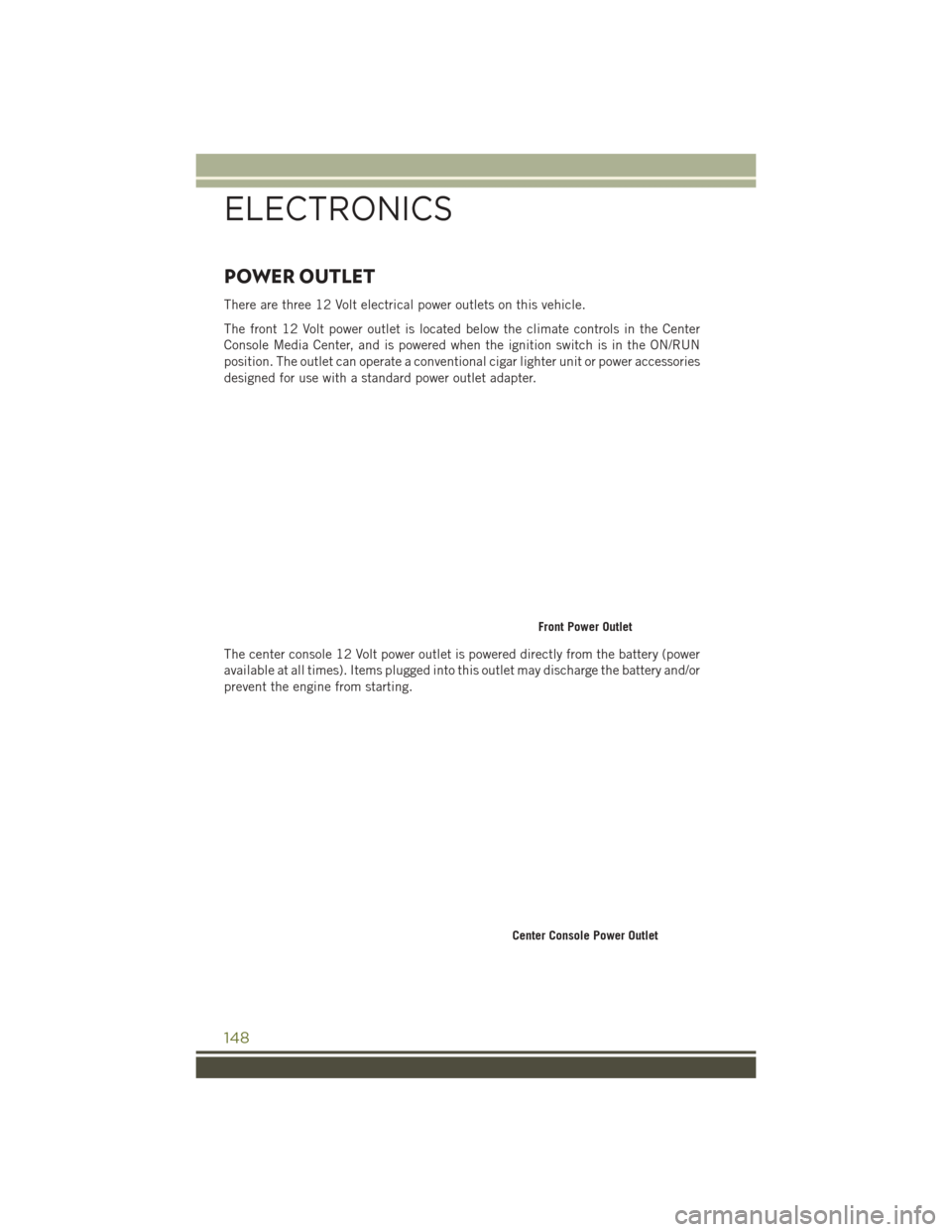
There are three 12 Volt electrical power outlets on this vehicle.
The front 12 Volt power outlet is located below the climate controls in the Center
Console Media Center, and is powered when the ignition switch is in the ON/RUN
position. The outlet can operate a conventional cigar lighter unit or power accessories
designed for use with a standard power outlet adapter.
The center console 12 Volt power outlet is powered directly from the battery (power
available at all times). Items plugged into this outlet may discharge the battery and/or
prevent the engine from starting.
Front Power Outlet
Center Console Power Outlet
ELECTRONICS
148
Page 151 of 236
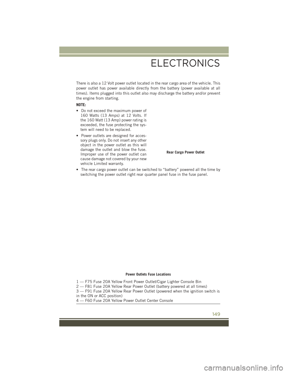
There is also a 12 Volt power outlet located in the rear cargo area of the vehicle. This
power outlet has power available directly from the battery (power available at all
times). Items plugged into this outlet also may discharge the battery and/or prevent
the engine from starting.
NOTE:
• Do not exceed the maximum power of160 Watts (13 Amps) at 12 Volts. If
the 160 Watt (13 Amp) power rating is
exceeded, the fuse protecting the sys-
tem will need to be replaced.
• Power outlets are designed for acces- sory plugs only. Do not insert any other
object in the power outlet as this will
damage the outlet and blow the fuse.
Improper use of the power outlet can
cause damage not covered by your new
vehicle Limited warranty.
• The rear cargo power outlet can be switched to “battery” powered all the time by switching the power outlet right rear quarter panel fuse in the fuse panel.
Rear Cargo Power Outlet
Power Outlets Fuse Locations
1 — F75 Fuse 20A Yellow Front Power Outlet/Cigar Lighter Console Bin
2 — F81 Fuse 20A Yellow Rear Power Outlet (battery powered at all times)
3 — F91 Fuse 20A Yellow Rear Power Outlet (powered when the ignition switch is
in the ON or ACC position)
4 — F60 Fuse 20A Yellow Power Outlet Center Console
ELECTRONICS
149
Page 152 of 236
WIRELESS CHARGING PAD
Wireless Charging Pad — If Equipped
Your vehicle may be equipped with a wireless charging pad located inside the upper
portion of the center console. This charging pad is designed to wirelessly charge your
Qi enabled mobile phone. Qi is a standard that uses magnetic induction to transfer
power to your mobile device.
Your mobile phone must be designed for
Qi wireless charging, be equipped with
an aftermarket sleeve or equipped with a
back plate from your mobile phone pro-
vider, or an online or local electronics
retailer. The wireless charging pad is
equipped with an anti-slip mat, an ad-
justable cradle to hold your mobile phone
in place and an LED indicator light.
NOTE:
Visit UconnectPhone.com for supported
mobile phones and compatible aftermar-
ket sleeves.
Wireless Charging Pad
ELECTRONICS
150
Page 156 of 236
The NEUTRAL position allows vehicles with 2-speed Four-Wheel Drive to be flat
towed (with all wheels on the ground) without damaging the drivetrain. Refer to
“Recreational Towing” for instructions on shifting into and out of NEUTRAL.
NOTE:
In 4X4 LOW the engine speed is approximately three times that of the normal driving
mode at a given road speed. Take care not to overspeed the engine and do not exceed
25 mph (40 km/h).
Shifting Procedures
4X4 HI To 4X4 LOW
With the vehicle at speeds of 0 to 3 mph (0 to 5 km/h), the ignition switch in the ON
position or the engine running, shift the transmission into NEUTRAL, and press the
“4WD LOW” button once. The “4WD LOW” indicator light in the instrument cluster
will begin to flash and remain on solid when the shift is complete.
NOTE:
If shift conditions/interlocks are not met a message will flash from the Electronic
Vehicle Information Center (EVIC)/Driver Information Display (DID) with instructions
on how to complete the requested shift. Refer to “Electronic Vehicle Information
Center (EVIC)/Driver Information Display (DID)” in “Understanding Your Instrument
Panel” on the DVD for further information.
4X4 LOW To 4X4 HI
With the vehicle at speeds of 0 to 3 mph (0 to 5 km/h), the ignition switch in the ON
position or the engine running, shift the transmission into NEUTRAL, and press the
“4WD LOW” button once. The “4WD LOW” indicator light in the instrument cluster
will flash and go out when the shift is complete.
NOTE:
If shift conditions/interlocks are not met a message will flash from the Electronic
Vehicle Information Center (EVIC)/Driver Information Display (DID) with instructions
on how to complete the requested shift. Refer to “Electronic Vehicle Information
Center (EVIC)/Driver Information Display (DID)” in “Understanding Your Instrument
Panel” on the DVD for further information.
OFF-ROAD CAPABILITIES
154
Page 157 of 236
REAR ELECTRONIC LOCKER (E-LOCKER) SYSTEM
The Rear E-Locker System features a mechanical locking rear differential to provide
better traction in the 4WD LOW position. The “REAR LOCK” button is on the
Selec-Terrain Knob.
Activating The Rear E-Locker
To activate the Rear E-Locker System, the following conditions must be met:
• The 4WD system must be in 4WD LOW.
• The ignition switch in the ON position or the engine running.
• Vehicle speed must be below 15 MPH (24 km/h).
• To engage Rear E-Locker, push the REAR LOCK button once.
Deactivating The Rear E-Locker System
To deactivate the Rear E-Locker System, the following conditions must be met:
• Rear E-Locker must be engaged, and the REAR LOCK indicator light on.
• The ignition switch in the ON position or the engine running.
• To disengage Rear E-Locker , push the REAR LOCK button once.
NOTE:
• It may also be necessary to drive slowly steering back and forth to completeengagement and disengagement of the E- Locker.
• When engaging Rear E-Locker, the indicator lights in the instrument cluster and on the REAR LOCK button will begin to flash. When the shift is complete the REAR
LOCK indicator lights will remain on.
• When disengaging Rear E-Locker, the indicator lights in the instrument cluster and on the REAR LOCK button will begin to flash. When the shift is complete the
REAR LOCK indicator lights will remain off.
• Shifting into or out of Rear E-Locker is possible with the vehicle completely stopped; however, difficulty may occur due to the mating clutch teeth not being
properly aligned. Several attempts may be required for clutch teeth alignment and
shift completion to occur. The preferred method is for the vehicle to be rolling,
below 15 MPH (24 km/h), while including right and left steering maneuvers to
allow for the clutch teeth to align.
• The Rear E-Locker System must be disengaged prior to taking the vehicle out of 4X4 LOW range. If 4X4 LOW shift conditions/interlocks are not met, a message will
flash from the Electronic Vehicle Information Center (EVIC)/Driver Information
Display with instructions on how to complete the requested shift.
OFF-ROAD CAPABILITIES
155
Page 163 of 236
1. Bring the vehicle to a complete stop and shift the transmission to PARK.
2. Turn the engine OFF.
3. Turn the ignition switch to the ON/RUN position, but do not start the engine.
4. Press and hold the brake pedal.
5. Shift the transmission into NEUTRAL.
6. Using a ballpoint pen or similar object, push and hold the recessed NEUTRAL (N)button (located by the selector switch) for four seconds. The light behind the
NEUTRAL (N) symbol will blink, indicating shift in progress. The light will stop
blinking (stay on solid) when the shift to NEUTRAL (N) is complete.
7. After the shift is completed and the NEUTRAL (N) light stays on, release the NEUTRAL (N) button.
8. Start the engine.
9. Release the parking brake.
10. Shift the transmission into REVERSE.
11. Release the brake pedal for five seconds and ensure that there is no vehicle movement.
12. Shift the transmission to NEUTRAL.
13. Apply the parking brake.
14. Shift the transmission into PARK, turn the engine OFF, and remove the key fob.
15. Attach the vehicle to the tow vehicle using a suitable tow bar.
16. Turn the ignition to the ON/RUN position, but do not start the engine.
17. Press and hold the brake pedal.
18. Release the parking brake.
19. Turn the ignition OFF, remove the Key Fob, and release the brake pedal.
NOTE:
• Steps 1 through 5 are requirements that must be met before pushing the NEUTRAL (N) button, and must continue to be met until the shift has been
completed. If any of these requirements are not met before pushing the NEUTRAL
(N) button or are no longer met during the shift, then the NEUTRAL (N) indicator
light will flash continuously until all requirements are met or until the NEUTRAL
(N) button is released.
• The ignition switch must be in the ON/RUN position for a shift to take place and for the position indicator lights to be operable. If the ignition switch is not in the
ON/RUN position, the shift will not take place and no position indicator lights will
be on or flashing.
• A flashing NEUTRAL (N) position indicator light indicates that shift requirements have not been met.
UTILITY
161
Page 164 of 236
Shifting Out Of NEUTRAL (N)
Use the following procedure to prepare your vehicle for normal usage.
1. Bring the vehicle to a complete stop, leaving it connected to the tow vehicle.
2. Apply the parking brake.
3. Turn the ignition switch to the ON/RUN position, but do not start the engine.
4. Press and hold the brake pedal.
5. Shift the transmission into NEUTRAL.
6. Using a ballpoint pen or similar object, push and hold the recessed power transferunit NEUTRAL (N) button (located by the selector switch) for one second.
7.
When the NEUTRAL (N) indicator light turns off, release the NEUTRAL (N) button.
8. After the NEUTRAL (N) button has been released, the power transfer unit will shift to the position indicated by the selector switch.
NOTE:
When shifting the power transfer unit out of NEUTRAL (N), the engine should remain
OFF to avoid gear clash.
9. Shift the transmission into PARK.
10. Release the brake pedal.
11. Disconnect vehicle from the tow vehicle.
12. Start the engine.
13. Press and hold the brake pedal.
14. Release the parking brake.
15. Shift the transmission into DRIVE, release the brake pedal, and check that the vehicle operates normally.
16. Re-enable the Auto Park Brake feature, if desired.
NOTE:
• Steps 1 through 5 are requirements that must be met before pushing the NEUTRAL (N) button, and must continue to be met until the shift has been
completed. If any of these requirements are not met before pushing the NEUTRAL
(N) button or are no longer met during the shift, the NEUTRAL (N) indicator light
will flash continuously until all requirements are met or until the NEUTRAL (N)
button is released.
• The ignition switch must be in the ON/RUN position for a shift to take place and for the position indicator lights to be operable. If the ignition switch is not in the
ON/RUN position, the shift will not take place and no position indicator lights will
be on or flashing.
• A flashing NEUTRAL (N) position indicator light indicates that shift requirements have not been met.
UTILITY
162
Page 165 of 236
ROADSIDE ASSISTANCE
Dial toll-free 1-800-521-2779 for U.S. Residents or 1-800-363-4869 for Canadian
Residents.
• Provide your name, vehicle identification number, license plate number, and yourlocation, including the telephone number from which you are calling.
• Briefly describe the nature of the problem and answer a few simple questions.
• You will be given the name of the service provider and an estimated time of arrival. If you feel you are in an “unsafe situation”, please let us know. With your consent,
we will contact local police or safety authorities.
INSTRUMENT CLUSTER WARNING LIGHTS
– Low Fuel Warning Light
This warning light indicates when the fuel level reaches approximately 2.0 gal (7.8 L).
This light will turn on and a single chime will sound.
- Charging System Light
This light shows the status of the electrical charging system. If the charging system
light remains on, it means that the vehicle is experiencing a problem with the
charging system.
We recommend you do not continue driving if the charging system light is on. Have
the vehicle serviced immediately.
- Oil Pressure Warning Light
This light indicates low engine oil pressure. If the light turns on while driving, stop
the vehicle and shut off the engine as soon as possible. A chime will sound for four
minutes when this light turns on.
We recommend you do not operate the vehicle or engine damage will occur. Have the
vehicle serviced immediately.
- Anti-Lock Brake (ABS) Light
This light monitors the Anti-Lock Brake System (ABS). The light will turn on when the
ignition switch is turned to the ON/RUN position and may stay on for as long as four
seconds.
If the ABS light remains on or turns on while driving, it indicates that the Anti-Lock
portion of the brake system is not functioning and that service is required. However, the
conventional brake system will continue to operate normally if the BRAKE warning light
is not on.
WHAT TO DO IN EMERGENCIES
163