light JEEP CHEROKEE 2016 KL / 5.G Workshop Manual
[x] Cancel search | Manufacturer: JEEP, Model Year: 2016, Model line: CHEROKEE, Model: JEEP CHEROKEE 2016 KL / 5.GPages: 236, PDF Size: 11.24 MB
Page 195 of 236
TO OPEN AND CLOSE THE HOOD
Two latches must be released to open the hood.
1. Pull the hood release lever located under the drivers side of the instrument panel.
2. Move to the outside of the vehicle and pull the safety latch release lever forward(toward you). The safety latch release lever is located behind the front edge of the
hood, slightly off-center to the right.
CAUTION!
To prevent possible damage, do not slam the hood to close it. Lower the hood until
it is open approximately 6 inches (15 cm), and then drop it. This should secure
both latches. Never drive your vehicle unless the hood is fully closed, with both
latches engaged.
WARNING!
Be sure the hood is fully latched before driving your vehicle. If the hood is not fully
latched, it could open when the vehicle is in motion and block your vision. Failure
to follow this warning could result in serious injury or death.
MAINTAINING YOUR VEHICLE
193
Page 202 of 236
FLEXIBLE FUEL (2.4L ENGINE ONLY) — IF EQUIPPED
E-85 General Information
The information in this section is unique for Flexible Fuel vehicles only. These
vehicles can be identified by a unique fuel filler door label that statesEthanol (E-85)
or Unleaded Gasoline Only and a yellow fuel cap. Refer to the Owner’s Manual on the
DVD for further information.
CAUTION!
Only vehicles with the E-85 fuel filler door label or a yellow gas cap can operate on
E-85.
MAINTENANCE PROCEDURES
For information on the maintenance procedures for your vehicle, please refer to
“Maintenance Procedures” in “Maintaining Your Vehicle” in your Owner’s Manual or
applicable supplement on the DVD for further details.
MAINTENANCE SCHEDULE
Your vehicle is equipped with an automatic oil change indicator system. The oil
change indicator system will remind you that it is time to take your vehicle in for
scheduled maintenance.
Based on engine operation conditions, the oil change indicator message will
illuminate. This means that service is required for your vehicle. Operating conditions
such as frequent short-trips, trailer tow, extremely hot or cold ambient temperatures
will influence when the “Oil Change Required” message is displayed. Severe
Operating Conditions can cause the change oil message to illuminate as early as
3,500 miles (5,600 km) since last reset. Have your vehicle serviced as soon as
possible, within the next 500 miles (805 km).
Your authorized dealer will reset the oil change indicator message after completing the
scheduled oil change. If a scheduled oil change is performed by someone other than
your authorized dealer, the message can be reset by referring to the steps described
under “Instrument Cluster Warning Lights” in “What To Do In Emergencies” in this
guide or “Electronic Vehicle Information Center (EVIC)” or “Driver Information Display
(DID)” in “Understanding Your Instrument Panel” in your Owners Manual on the DVD for
further information.
MAINTAINING YOUR VEHICLE
200
Page 203 of 236
NOTE:
Under no circumstances should oil change intervals exceed 10,000 miles
(16,000 km), twelve months or 350 hours of engine run time, whichever comes first.
The 350 hours of engine run or idle time is generally only a concern for fleet
customers.
Severe Duty All Models
Change Engine Oil at 4,000 miles (6,500 km) if the vehicle is operated in a dusty
and off road environment or is operated predominately at idle or only very low engine
RPM’s. This type of vehicle use is considered Severe Duty.
Once A Month Or Before A Long Trip:
• Check engine oil level.
• Check windshield washer fluid level.
• Check tire pressure and look for unusual wear or damage. Rotate tires at the firstsign of irregular wear, even if it occurs before the oil indicator system turns on.
• Check the fluid levels of the coolant reservoir and brake master cylinder, fill as needed.
• Check function of all interior and exterior lights.
Required Maintenance Intervals.
Refer to the maintenance schedules on the following page for the required mainte-
nance intervals.
At Every Oil Change Interval As Indicated By Oil Change Indicator System:
• Change oil and filter
• Rotate the tires. Rotate at the first sign of irregular wear, even if it occurs before the oil
indicator system turns on.
• Inspect battery and clean and tighten terminals as required
• Inspect brake pads, shoes, rotors, drums, hoses and park brake
• Inspect engine cooling system protection and hoses
• Inspect exhaust system
• Inspect engine air cleaner if using in dusty or off-road conditions
MAINTAINING YOUR VEHICLE
201
Page 207 of 236
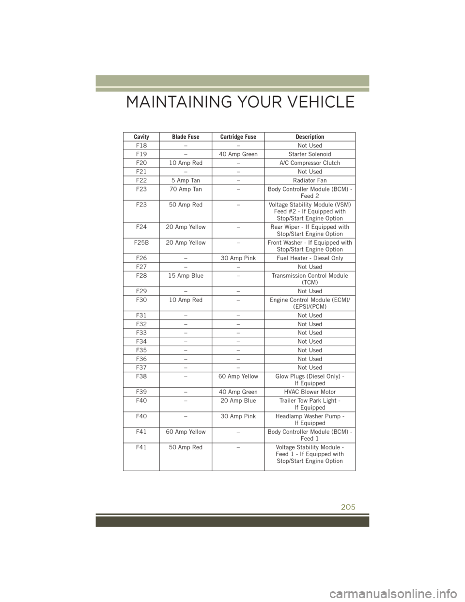
Cavity Blade Fuse Cartridge FuseDescription
F18 – – Not Used
F19 –40 Amp Green Starter Solenoid
F20 10 Amp Red –A/C Compressor Clutch
F21 – – Not Used
F22 5 Amp Tan –Radiator Fan
F23 70 Amp Tan – Body Controller Module (BCM) -
Feed 2
F23 50 Amp Red – Voltage Stability Module (VSM)
Feed #2 - If Equipped withStop/Start Engine Option
F24 20 Amp Yellow –Rear Wiper - If Equipped with
Stop/Start Engine Option
F25B 20 Amp Yellow – Front Washer - If Equipped with
Stop/Start Engine Option
F26 –30 Amp Pink Fuel Heater - Diesel Only
F27 – – Not Used
F28 15 Amp Blue –Transmission Control Module
(TCM)
F29 – – Not Used
F30 10 Amp Red – Engine Control Module (ECM)/
(EPS)/(PCM)
F31 – – Not Used
F32 – – Not Used
F33 – – Not Used
F34 – – Not Used
F35 – – Not Used
F36 – – Not Used
F37 – – Not Used
F38 –60 Amp Yellow Glow Plugs (Diesel Only) -
If Equipped
F39 –40 Amp Green HVAC Blower Motor
F40 –20 Amp Blue Trailer Tow Park Light -
If Equipped
F40 –30 Amp Pink Headlamp Washer Pump -
If Equipped
F41 60 Amp Yellow – Body Controller Module (BCM) -
Feed 1
F41 50 Amp Red –Voltage Stability Module -
Feed 1 - If Equipped with Stop/Start Engine Option
MAINTAINING YOUR VEHICLE
205
Page 208 of 236
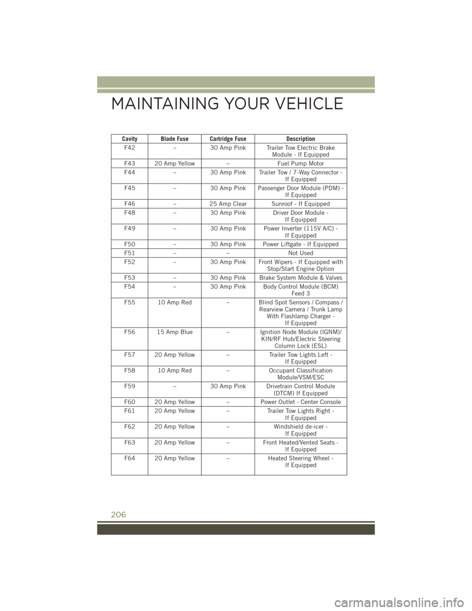
Cavity Blade Fuse Cartridge FuseDescription
F42 –30 Amp Pink Trailer Tow Electric Brake
Module - If Equipped
F43 20 Amp Yellow –Fuel Pump Motor
F44 –30 Amp Pink Trailer Tow / 7-Way Connector -
If Equipped
F45 –30 Amp Pink Passenger Door Module (PDM) -
If Equipped
F46 –25 Amp Clear Sunroof - If Equipped
F48 –30 Amp Pink Driver Door Module -
If Equipped
F49 –30 Amp Pink Power Inverter (115V A/C) -
If Equipped
F50 –30 Amp Pink Power Liftgate - If Equipped
F51 – – Not Used
F52 –30 Amp Pink Front Wipers - If Equipped with
Stop/Start Engine Option
F53 –30 Amp Pink Brake System Module & Valves
F54 –30 Amp Pink Body Control Module (BCM)
Feed 3
F55 10 Amp Red – Blind Spot Sensors / Compass /
Rearview Camera / Trunk LampWith Flashlamp Charger - If Equipped
F56 15 Amp Blue – Ignition Node Module (IGNM)/
KIN/RF Hub/Electric SteeringColumn Lock (ESL)
F57 20 Amp Yellow –Trailer Tow Lights Left -
If Equipped
F58 10 Amp Red –Occupant Classification
Module/VSM/ESC
F59 –30 Amp Pink Drivetrain Control Module
(DTCM) If Equipped
F60 20 Amp Yellow –Power Outlet - Center Console
F61 20 Amp Yellow –Trailer Tow Lights Right -
If Equipped
F62 20 Amp Yellow –Windshield de-icer -
If Equipped
F63 20 Amp Yellow –Front Heated/Vented Seats -
If Equipped
F64 20 Amp Yellow –Heated Steering Wheel -
If Equipped
MAINTAINING YOUR VEHICLE
206
Page 209 of 236
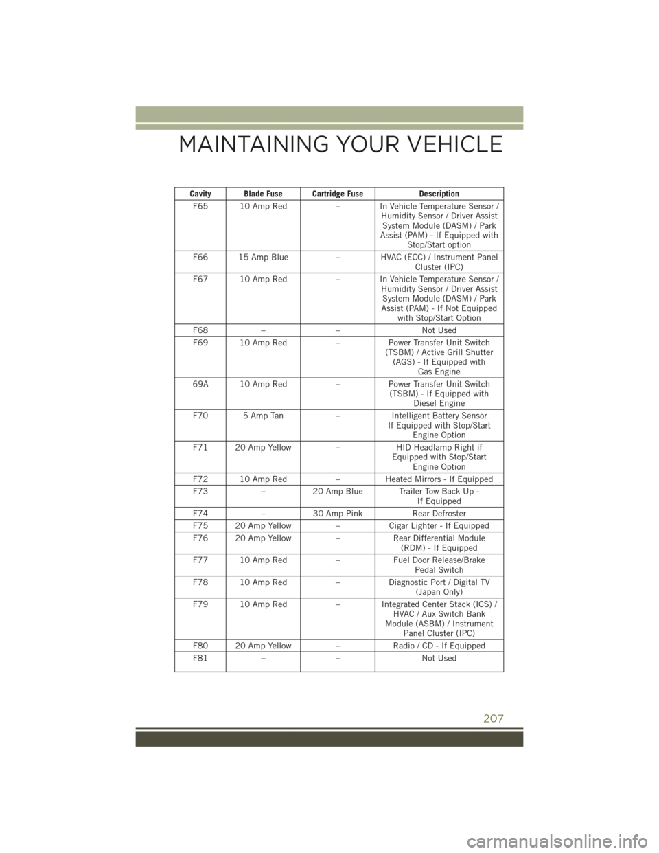
Cavity Blade Fuse Cartridge FuseDescription
F65 10 Amp Red – In Vehicle Temperature Sensor /
Humidity Sensor / Driver AssistSystem Module (DASM) / Park
Assist (PAM) - If Equipped with Stop/Start option
F66 15 Amp Blue – HVAC (ECC) / Instrument Panel
Cluster (IPC)
F67 10 Amp Red – In Vehicle Temperature Sensor /
Humidity Sensor / Driver AssistSystem Module (DASM) / Park
Assist (PAM) - If Not Equipped with Stop/Start Option
F68 – – Not Used
F69 10 Amp Red –Power Transfer Unit Switch
(TSBM) / Active Grill Shutter (AGS) - If Equipped with Gas Engine
69A 10 Amp Red –Power Transfer Unit Switch
(TSBM) - If Equipped with Diesel Engine
F70 5 Amp Tan –Intelligent Battery Sensor
If Equipped with Stop/Start Engine Option
F71 20 Amp Yellow –HID Headlamp Right if
Equipped with Stop/Start Engine Option
F72 10 Amp Red –Heated Mirrors - If Equipped
F73 –20 Amp Blue Trailer Tow Back Up -
If Equipped
F74 –30 Amp Pink Rear Defroster
F75 20 Amp Yellow –Cigar Lighter - If Equipped
F76 20 Amp Yellow –Rear Differential Module
(RDM) - If Equipped
F77 10 Amp Red –Fuel Door Release/Brake
Pedal Switch
F78 10 Amp Red –Diagnostic Port / Digital TV
(Japan Only)
F79 10 Amp Red – Integrated Center Stack (ICS) /
HVAC / Aux Switch Bank
Module (ASBM) / Instrument Panel Cluster (IPC)
F80 20 Amp Yellow –Radio / CD - If Equipped
F81 – – Not Used
MAINTAINING YOUR VEHICLE
207
Page 211 of 236
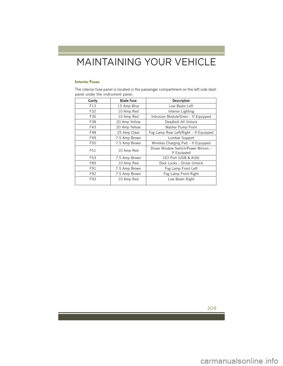
Interior Fuses
The interior fuse panel is located in the passenger compartment on the left side dash
panel under the instrument panel.
CavityBlade Fuse Description
F13 15 Amp Blue Low Beam Left
F32 10 Amp Red Interior Lighting
F36 10 Amp Red Intrusion Module/Siren – If Equipped
F38 20 Amp Yellow Deadbolt All Unlock
F43 20 Amp Yellow Washer Pump Front
F48 25 Amp Clear Fog Lamp Rear Left/Right – If Equipped
F49 7.5 Amp Brown Lumbar Support
F50 7.5 Amp Brown Wireless Charging Pad – If Equipped
F51 10 Amp Red Driver Window Switch/Power Mirrors –
If Equipped
F53 7.5 Amp Brown UCI Port (USB & AUX)
F89 10 Amp Red Door Locks – Driver Unlock
F91 7.5 Amp Brown Fog Lamp Front Left
F92 7.5 Amp Brown Fog Lamp Front Right
F93 10 Amp Red Low Beam Right
MAINTAINING YOUR VEHICLE
209
Page 212 of 236
ADDING FUEL
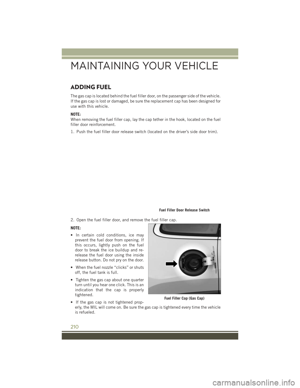
The gas cap is located behind the fuel filler door, on the passenger side of the vehicle.
If the gas cap is lost or damaged, be sure the replacement cap has been designed for
use with this vehicle.
NOTE:
When removing the fuel filler cap, lay the cap tether in the hook, located on the fuel
filler door reinforcement.
1. Push the fuel filler door release switch (located on the driver’s side door trim).
2. Open the fuel filler door, and remove the fuel filler cap.
NOTE:
• In certain cold conditions, ice mayprevent the fuel door from opening. If
this occurs, lightly push on the fuel
door to break the ice buildup and re-
release the fuel door using the inside
release button. Do not pry on the door.
• When the fuel nozzle “clicks” or shuts off, the fuel tank is full.
• Tighten the gas cap about one quarter turn until you hear one click. This is an
indication that the cap is properly
tightened.
• If the gas cap is not tightened prop- erly, the MIL will come on. Be sure the gas cap is tightened every time the vehicle
is refueled.
Fuel Filler Door Release Switch
Fuel Filler Cap (Gas Cap)
MAINTAINING YOUR VEHICLE
210
Page 213 of 236
CAUTION!
• Damage to the fuel system or emission control system could result from usingan improper fuel filler cap. A poorly fitting cap could let impurities into the fuel
system. Also, a poorly fitting aftermarket cap can cause the “Malfunction
Indicator Light (MIL)” to illuminate, due to fuel vapors escaping from the
system.
• A poorly fitting fuel filler cap may cause the MIL to turn on.
•
To avoid fuel spillage and overfilling, do not “top off” the fuel tank after filling.
WARNING!
• Never have any smoking materials lit in or near the vehicle when the gas cap is
removed or the tank is being filled.
• Never add fuel when the engine is running. This is in violation of most state and
federal fire regulations and may cause the MIL to turn on.
• A fire may result if gasoline is pumped into a portable container that is inside
of a vehicle. You could be burned. Always place gas containers on the ground
while filling.
Emergency Fuel Filler Door Release
If you are unable to open the fuel filler door, use the fuel filler door emergency
release.
1. Open the liftgate.
2. Remove access door located on right interior trim panel for release cable with the tip of your key.
3. Grab the release cable tether and pull up to release the fuel filler door.
Loose Fuel Filler Cap Message
If the vehicle diagnostic system determines that the fuel filler cap is loose,
improperly installed, or damaged, a “CHECK GASCAP” message will be displayed in
the Electronic Vehicle Information Center (EVIC) or Driver Information Display (DID).
Refer to “Electronic Vehicle Information (EVIC) or "Driver Information Display (DID)”
in “Understanding Your Instrument Panel” for further information. Tighten the fuel
filler cap until a “clicking” sound is heard. This is an indication that the fuel filler cap
is properly tightened. Refer to “Onboard Diagnostic System” in “Maintaining Your
Vehicle” for further information.
MAINTAINING YOUR VEHICLE
211
Page 220 of 236
AUTHENTIC ACCESSORIES BY MOPAR
•The following highlights just some of the many Authentic Jeep Accessories by
MOPAR featuring a fit, finish, and functionality specifically for your Jeep Cherokee.
•In choosing Authentic Accessories you gain far more than expressive style, premium
protection, or extreme entertainment, you also benefit from enhancing your vehicle
with accessories that have been thoroughly tested and factory-approved.
• For the full line of Authentic Jeep Accessories by Mopar, visit your local dealership or online at mopar.com for U.S. residents and mopar.ca for Canadian residents.
NOTE:
All parts are subject to availability.
JEEP CARGO MANAGEMENT SYSTEM:
• Off Road Kit • Roadside Safety Kit • Cooler
• First Aid Kit • Collapsible Tote
EXTERIOR:
• Rock Rails • Front End Cover • Hood Decal
• Wheels • Splash Guards• Skid Plates
• Wheel Locks • Locking Gas Cap
INTERIOR:
• Premium Floor Mats • Emergency Roadside Kit • Molded Cargo Tray
• Security Cover • Bright Pedal Kit • Ambient Light Kit
• Slush Mats • Door Sill Guards • Katzkin Leather Interiors
• Cargo Area Cover
ELECTRONICS:
• MOPAR Web (WiFi) • Park Distance Sensors • Rear View Camera
• Remote Start • Speaker Upgrades • Electronic Vehicle
Tracking System
CARRIERS:
• Hitch-mount Bike Carrier • Sport Utility Bars • Roof-mount Bike Carrier
• Roof Top Cargo Basket • Roof-mount Ski and Snowboard Carrier• Roof Cargo Box Carrier
MOPAR® ACCESSORIES
218