light JEEP CHEROKEE 2017 KL / 5.G User Guide
[x] Cancel search | Manufacturer: JEEP, Model Year: 2017, Model line: CHEROKEE, Model: JEEP CHEROKEE 2017 KL / 5.GPages: 615, PDF Size: 5.72 MB
Page 394 of 615
NOTE:
•Your vehicle may be transmitting data as authorized by
the subscriber.
• The 9–1–1 and ASSIST buttons will only function if you
are connected to an operable 1X(voice/data) or 3G(data)
network. Other Uconnect services will only be operable
if your Uconnect Access service is active and you are
connected to an operable 1X(voice/data) or 3G(data)
network.
ASSIST Call
The ASSIST Button is used to automatically connect you to
any one of the following support centers:
• Roadside Assistance – If you get a flat tire, or need a tow,
just push the ASSIST button and you’ll be connected to
someone who can help. Roadside Assistance will know
what vehicle you’re driving and its location. Additional
fees may apply for roadside Assistance.
•
Uconnect Access Customer Care – In-vehicle support for
Uconnect Access and Uconnect Access Via Mobile fea-
tures.
• Vehicle Customer Care – Total support for all other
vehicle issues. 9-1-1 Call
1. Push the 9-1-1 Call button on the Rearview Mirror.
NOTE:
In case the 9-1-1 Call button is pushed in error,
there will be a 10 second delay before the 9-1-1 Call system
initiates a call to a 9-1-1 operator. To cancel the 9-1-1 Call
connection, push the 9-1-1 Call button on the Rearview
Mirror or press the cancellation button on the Device
Screen. Termination of the 9-1-1 Call will turn off the green
LED light on the Rearview Mirror.
2. The LED light located between the ASSIST and 9-1-1 buttons on the Rearview Mirror will turn green once a
connection to a 9-1-1 operator has been made.
3.
Once a connection between the vehicle and a 9-1-1 operator
is made, the 9-1-1 Call system may transmit the following
important vehicle information to a 9-1-1 operator:
• Indication that the occupant placed a 9-1-1 Call.
• The vehicle brand.
• The last known GPS coordinates of the vehicle.
4. You should be able to speak with the 9-1-1 operator through the vehicle audio system to determine if addi-
tional help is needed.
392 IN CASE OF EMERGENCY
Page 396 of 615
WARNING!(Continued)
•The 9-1-1 Call system is embedded into the vehicle’s
electrical system. Do not add aftermarket electrical
equipment to the vehicle’s electrical system. This
may prevent your vehicle from sending a signal to
initiate an emergency call. To avoid interference that
can cause the 9-1-1 Call system to fail, never add
aftermarket equipment (e.g., two-way mobile radio,
CB radio, data recorder, etc.) to your vehicle’s electri-
cal system or modify the antennas on your vehicle. IF
YOUR VEHICLE LOSES BATTERY POWER FOR
ANY REASON (INCLUDING DURING OR AFTER
AN ACCIDENT), THE UCONNECT FEATURES,
APPS AND SERVICES, AMONG OTHERS, WILL
NOT OPERATE.
• Modifications to any part of the 9-1-1 Call system
could cause the air bag system to fail when you need
it. You could be injured if the air bag system is not
there to help protect you. 9-1-1 Call System Limitations
Vehicles sold in Canada and Mexico
DO NOThave 9-1-1
Call system capabilities.
9-1-1 or other emergency line operators in Canada and
Mexico may not answer or respond to 9-1-1 system calls.
If the 9-1-1 Call system detects a malfunction, any of the
following may occur at the time the malfunction is de-
tected, and at the beginning of each ignition cycle:
• The Rearview Mirror light located between the ASSIST
and 9-1-1 buttons will continuously be illuminated red.
• The Device Screen will display the following message
“Vehicle device requires service. Please contact your
dealer.”
• An In-Vehicle Audio message will state “Vehicle device
requires service. Please contact your dealer.”
394 IN CASE OF EMERGENCY
Page 397 of 615
WARNING!
•Ignoring the Rearview Mirror light could mean you
will not have 9-1-1 Call services. If the Rearview
Mirror light is illuminated, have an authorized
dealer service the 9-1-1 Call system immediately.
• The Occupant Restraint Control module turns on the
air bag Warning Light on the instrument panel if a
malfunction in any part of the system is detected. If
the Air Bag Warning Light is illuminated, have an
authorized dealer service the Occupant Restraint
Control system immediately.
Even if the 9-1-1 Call system is fully functional, factors
beyond FCA US LLC’s control may prevent or stop the
9-1-1 Call system operation. These include, but are not
limited to, the following factors:
• Delayed accessories mode is active.
• The ignition is in the OFF position.
• The vehicle’s electrical systems are not intact.
• The 9-1-1 Call system software and/or hardware are
damaged during a crash. •
The vehicle battery loses power or becomes discon-
nected during a vehicle crash.
• 1X(voice/data) or 3G(data) network and/or Global Po-
sitioning Satellite signals are unavailable or obstructed.
• Equipment malfunction at the 9-1-1 operator facility.
• Operator error by the 9-1-1 operator.
• 1X(voice/data) or 3G(data) network congestion.
• Weather.
• Buildings, structures, geographic terrain, or tunnels.
WARNING!
ALWAYS obey traffic laws and pay attention to the
road. Some Uconnect Access services, including 9-1-1
and Assist, will NOT work without an operable
1X(voice/data) or 3G(data) network connection.
7
IN CASE OF EMERGENCY 395
Page 400 of 615
Replacing Exterior Bulbs
Bi-Xenon High Intensity Discharge (HID)
Headlamps — If Equipped
The headlamps contain a type of high voltage discharge
light source. High voltage can remain in the circuit even
with the headlamp switch off. Because of this, you should
not attempt to service a HID headlamp light source your-
self. If an HID headlamp light source fails, take your
vehicle to an authorized dealer for service.
NOTE:On vehicles equipped with HID headlamps, when
the headlamps are turned on, there is a blue hue to the
lights. This diminishes and becomes more white after
approximately 10 seconds, as the system charges.
WARNING!
A transient high voltage occurs at the bulb sockets of
HID headlamps when the headlamp switch is turned
ON. It may cause serious electrical shock or electrocu-
tion if not serviced properly. See your authorized
dealer for service.
Bi-Halogen Headlamps
1. Remove the 3 hex head screws from the wheel liner.
2. Pull the exterior edge of the liner towards the tire to gain access to the headlamp bulb cap.
3.
Firmly grasp the cap and rotate it counterclockwise to
unlock it.
4. Firmly grasp the bulb and connector assembly and rotate counterclockwise to remove from the housing.
5. Disconnect the bulb from the electrical connector and then connect the replacement bulb.
CAUTION!
Do not touch the new bulb with your fingers. Oil
contamination will severely shorten bulb life. If the
bulb comes in contact with any oily surface, clean the
bulb with rubbing alcohol.
6. Install the bulb and connector assembly into the head- lamp housing and rotate clockwise to lock it in place.
7. Install the bulb cap in the headlamp housing and rotate clockwise to lock it in place.
8. Install the 3 hex head screws into the wheel liner.
398 IN CASE OF EMERGENCY
Page 407 of 615
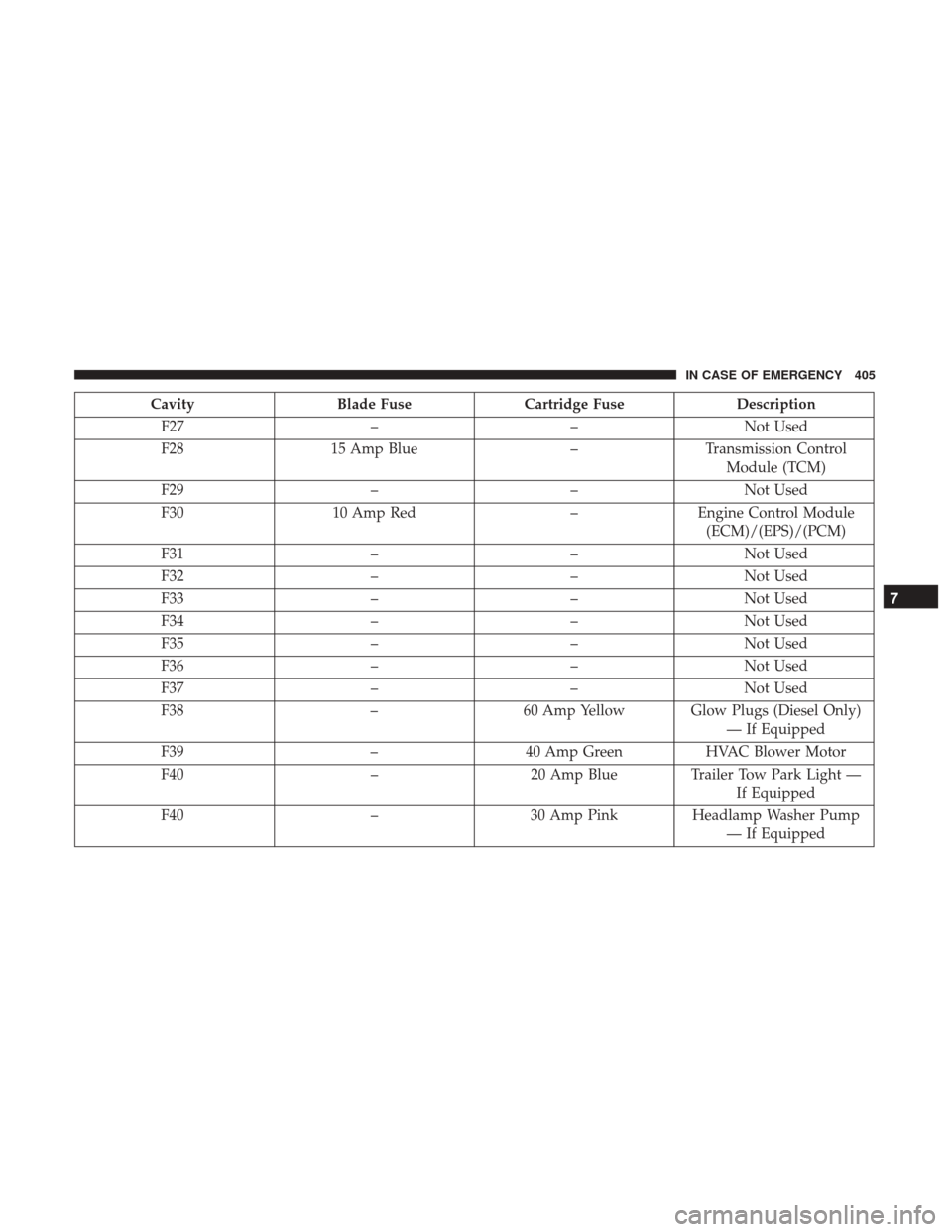
CavityBlade Fuse Cartridge Fuse Description
F27 ––Not Used
F28 15 Amp Blue –Transmission Control
Module (TCM)
F29 ––Not Used
F30 10 Amp Red –Engine Control Module
(ECM)/(EPS)/(PCM)
F31 ––Not Used
F32 ––Not Used
F33 ––Not Used
F34 ––Not Used
F35 ––Not Used
F36 ––Not Used
F37 ––Not Used
F38 –60 Amp Yellow Glow Plugs (Diesel Only)
— If Equipped
F39 –40 Amp Green HVAC Blower Motor
F40 –20 Amp Blue Trailer Tow Park Light —
If Equipped
F40 –30 Amp Pink Headlamp Washer Pump
— If Equipped
7
IN CASE OF EMERGENCY 405
Page 409 of 615
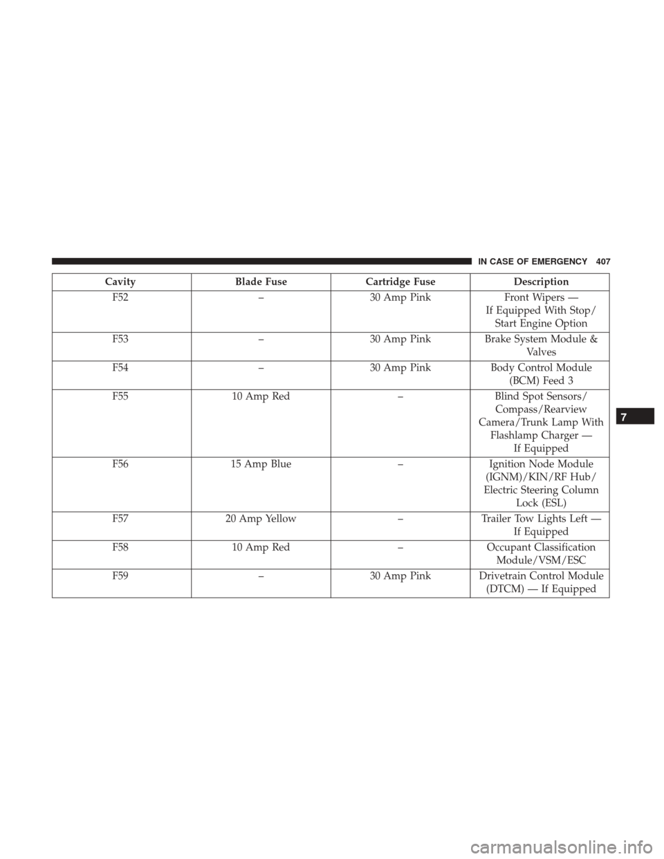
CavityBlade Fuse Cartridge Fuse Description
F52 –30 Amp Pink Front Wipers —
If Equipped With Stop/ Start Engine Option
F53 –30 Amp Pink Brake System Module &
Valves
F54 –30 Amp Pink Body Control Module
(BCM) Feed 3
F55 10 Amp Red –Blind Spot Sensors/
Compass/Rearview
Camera/Trunk Lamp With Flashlamp Charger — If Equipped
F56 15 Amp Blue –Ignition Node Module
(IGNM)/KIN/RF Hub/
Electric Steering Column Lock (ESL)
F57 20 Amp Yellow –Trailer Tow Lights Left —
If Equipped
F58 10 Amp Red –Occupant Classification
Module/VSM/ESC
F59 –30 Amp Pink Drivetrain Control Module
(DTCM) — If Equipped
7
IN CASE OF EMERGENCY 407
Page 410 of 615
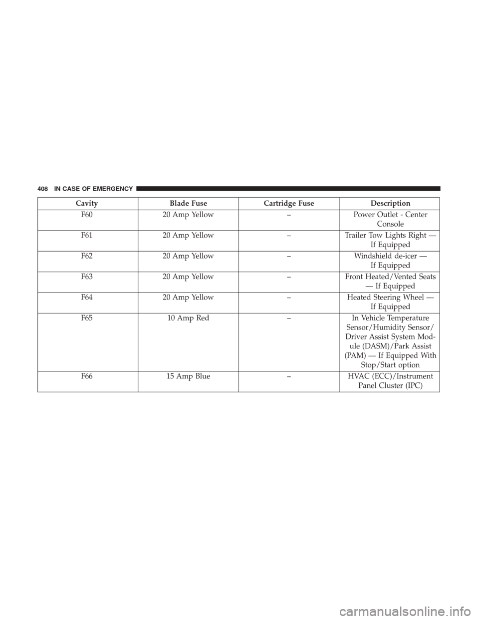
CavityBlade Fuse Cartridge Fuse Description
F60 20 Amp Yellow –Power Outlet - Center
Console
F61 20 Amp Yellow –Trailer Tow Lights Right —
If Equipped
F62 20 Amp Yellow –Windshield de-icer —
If Equipped
F63 20 Amp Yellow –Front Heated/Vented Seats
— If Equipped
F64 20 Amp Yellow –Heated Steering Wheel —
If Equipped
F65 10 Amp Red –In Vehicle Temperature
Sensor/Humidity Sensor/
Driver Assist System Mod- ule (DASM)/Park Assist
(PAM) — If Equipped With Stop/Start option
F66 15 Amp Blue –HVAC (ECC)/Instrument
Panel Cluster (IPC)
408 IN CASE OF EMERGENCY
Page 412 of 615
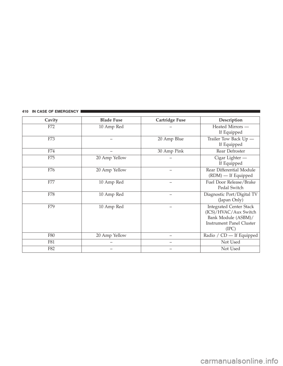
CavityBlade Fuse Cartridge Fuse Description
F72 10 Amp Red –Heated Mirrors —
If Equipped
F73 –20 Amp Blue Trailer Tow Back Up —
If Equipped
F74 –30 Amp Pink Rear Defroster
F75 20 Amp Yellow –Cigar Lighter —
If Equipped
F76 20 Amp Yellow –Rear Differential Module
(RDM) — If Equipped
F77 10 Amp Red –Fuel Door Release/Brake
Pedal Switch
F78 10 Amp Red –Diagnostic Port/Digital TV
(Japan Only)
F79 10 Amp Red –Integrated Center Stack
(ICS)/HVAC/Aux Switch Bank Module (ASBM)/
Instrument Panel Cluster (IPC)
F80 20 Amp Yellow –Radio / CD — If Equipped
F81 ––Not Used
F82 ––Not Used
410 IN CASE OF EMERGENCY
Page 415 of 615
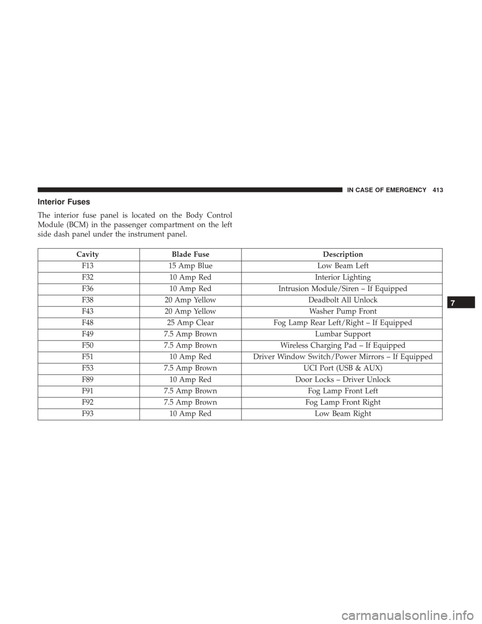
Interior Fuses
The interior fuse panel is located on the Body Control
Module (BCM) in the passenger compartment on the left
side dash panel under the instrument panel.
CavityBlade Fuse Description
F13 15 Amp Blue Low Beam Left
F32 10 Amp Red Interior Lighting
F36 10 Amp Red Intrusion Module/Siren – If Equipped
F38 20 Amp Yellow Deadbolt All Unlock
F43 20 Amp Yellow Washer Pump Front
F48 25 Amp Clear Fog Lamp Rear Left/Right – If Equipped
F49 7.5 Amp Brown Lumbar Support
F50 7.5 Amp Brown Wireless Charging Pad – If Equipped
F51 10 Amp RedDriver Window Switch/Power Mirrors – If Equipped
F53 7.5 Amp Brown UCI Port (USB & AUX)
F89 10 Amp Red Door Locks – Driver Unlock
F91 7.5 Amp Brown Fog Lamp Front Left
F92 7.5 Amp Brown Fog Lamp Front Right
F93 10 Amp Red Low Beam Right
7
IN CASE OF EMERGENCY 413
Page 423 of 615
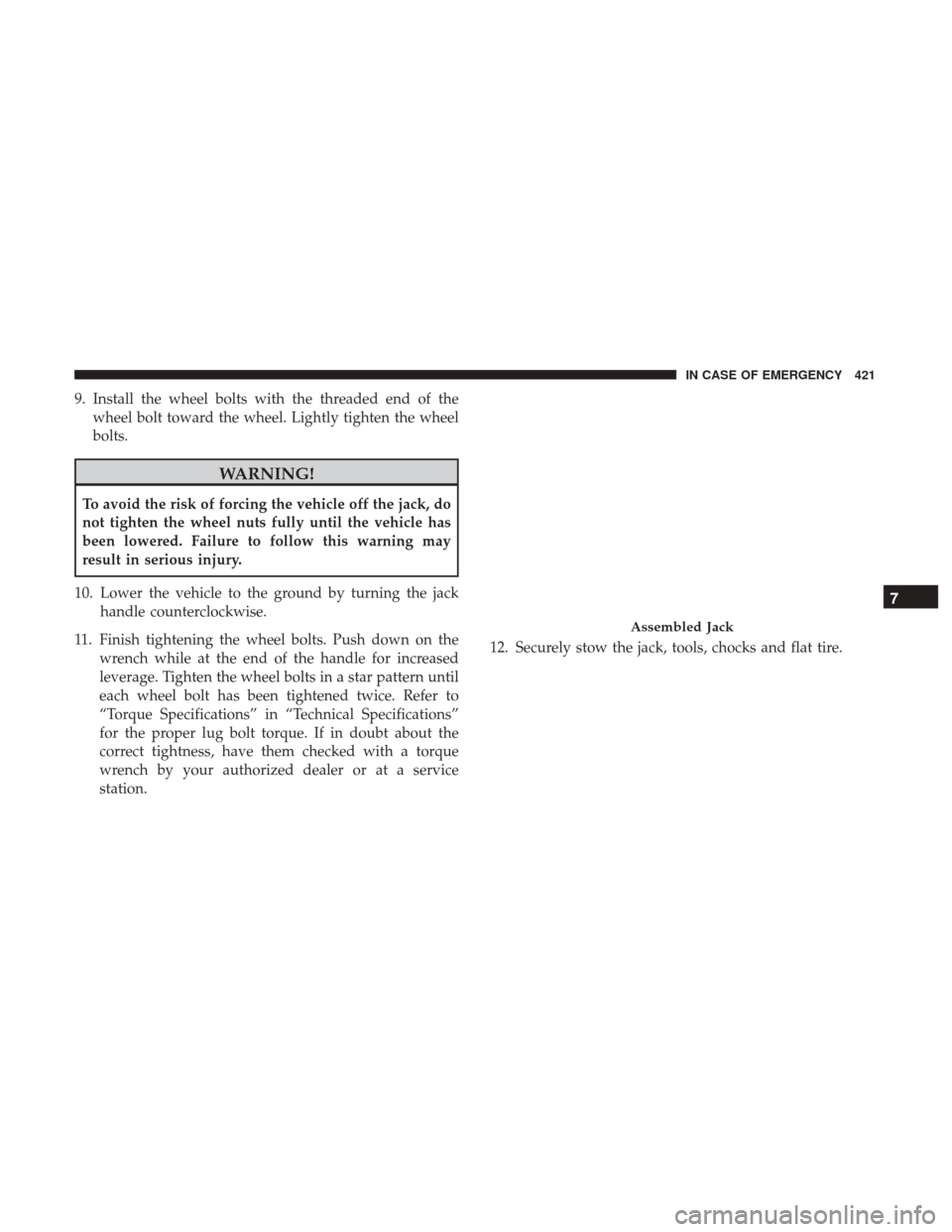
9. Install the wheel bolts with the threaded end of thewheel bolt toward the wheel. Lightly tighten the wheel
bolts.
WARNING!
To avoid the risk of forcing the vehicle off the jack, do
not tighten the wheel nuts fully until the vehicle has
been lowered. Failure to follow this warning may
result in serious injury.
10. Lower the vehicle to the ground by turning the jack handle counterclockwise.
11. Finish tightening the wheel bolts. Push down on the wrench while at the end of the handle for increased
leverage. Tighten the wheel bolts in a star pattern until
each wheel bolt has been tightened twice. Refer to
“Torque Specifications” in “Technical Specifications”
for the proper lug bolt torque. If in doubt about the
correct tightness, have them checked with a torque
wrench by your authorized dealer or at a service
station. 12. Securely stow the jack, tools, chocks and flat tire.
Assembled Jack
7
IN CASE OF EMERGENCY 421