door lock JEEP CHEROKEE 2017 KL / 5.G Owner's Guide
[x] Cancel search | Manufacturer: JEEP, Model Year: 2017, Model line: CHEROKEE, Model: JEEP CHEROKEE 2017 KL / 5.GPages: 615, PDF Size: 5.72 MB
Page 235 of 615
Enhanced Accident Response System
In the event of an impact, if the communication network
remains intact, and the power remains intact, depending
on the nature of the event, the ORC will determine whether
to have the Enhanced Accident Response System perform
the following functions:
•Cut off fuel to the engine.
• Flash hazard lights as long as the battery has power or
until the hazard light button is pressed. The hazard
lights can be deactivated by pressing the hazard light
button.
• Turn on the interior lights, which remain on as long as
the battery has power.
• Unlock the power door locks.
Enhanced Accident Response System Reset
Procedure
In order to reset the Enhanced Accident Response System
functions after an event, the ignition switch must be
changed from ignition START or ON/RUN to ignition OFF.
Carefully check the vehicle for fuel leaks in the engine compartment and on the ground near the engine compart-
ment and fuel tank before resetting the system and starting
the engine.
Maintaining Your Air Bag System
WARNING!
•
Modifications to any part of the air bag system could
cause it to fail when you need it. You could be
injured if the air bag system is not there to protect
you. Do not modify the components or wiring, in-
cluding adding any kind of badges or stickers to the
steering wheel hub trim cover or the upper right side
of the instrument panel. Do not modify the front
bumper, vehicle body structure, or add aftermarket
side steps or running boards.
• It is dangerous to try to repair any part of the air bag
system yourself. Be sure to tell anyone who works on
your vehicle that it has an air bag system.
• Do not attempt to modify any part of your air bag
system. The air bag may inflate accidentally or may
not function properly if modifications are made.
Take your vehicle to an authorized dealer for any air
bag system service. If your seat, including your trim
(Continued)
5
SAFETY 233
Page 246 of 615
2. Right outboard and center seating positions (1 and 2):Install the first child seat in the right outboard seating
position using lower anchorages A and B. Install the
second child seat using the center anchorages, C and D.
Do not use the outer anchorage closest to the opposite
door, E. Do not use the remaining left outboard seating
position (3) for any occupant. The center child restraint
will block the seat belt buckle for this position.
WARNING!
•Use anchorages C and D to install a LATCH-
compatible child restraint in the center seating posi-
tion (2). Do not install a LATCH-compatible child
restraint using anchorages B and C. This is not a
LATCH-compatible position in your vehicle.
• A child restraint installed in the center position (2)
will block the seat belt buckle for the empty left
outboard seat behind the driver (3). Do not use this
seat for another occupant.
• Never use the same lower anchorage to attach more
than one child restraint.
(Continued)
WARNING! (Continued)
•If you are installing three child restraints next to each
other, you must use the seat belt and the center tether
anchor for the center position. You must use the
LATCH anchors to install the child seat in position (3),
behind the driver. You may use either the LATCH
anchors or the vehicle’s seat belt for installing the child
seat in position (1), behind the front passenger. Please
refer to “Installing the LATCH-Compatible Child Re-
straint System” for typical installation instructions.
To Install A LATCH-Compatible Child Restraint
If the selected seating position has a Switchable Automatic
Locking Retractor (ALR) seat belt, stow the seat belt,
following the instructions below. See the section “Installing
Child Restraints Using the Vehicle Seat Belt” to check what
type of seat belt each seating position has.
1.
Loosen the adjusters on the lower straps and on the tether
strap of the child seat so that you can more easily attach
the hooks or connectors to the vehicle anchorages.
244 SAFETY
Page 257 of 615
WARNING!(Continued)
•NEVER place any objects under the floor mat (e.g.,
towels, keys, etc.). These objects could change the
position of the floor mat and may cause interference
with the accelerator, brake, or clutch pedals.
• If the vehicle carpet has been removed and re-
installed, always properly attach carpet to the floor
and check the floor mat fasteners are secure to the
vehicle carpet. Fully depress each pedal to check for
interference with the accelerator, brake, or clutch
pedals then re-install the floor mats.
• It is recommended to only use mild soap and water
to clean your floor mats. After cleaning, always check
your floor mat has been properly installed and is
secured to your vehicle using the floor mat fasteners
by lightly pulling mat.
Periodic Safety Checks You Should Make Outside
The Vehicle
Tires
Examine tires for excessive tread wear and uneven wear
patterns. Check for stones, nails, glass, or other objects
lodged in the tread or sidewall. Inspect the tread for cuts
and cracks. Inspect sidewalls for cuts, cracks, and bulges.
Check the wheel nuts for tightness. Check the tires (includ-
ing spare) for proper cold inflation pressure.
Lights
Have someone observe the operation of brake lights and
exterior lights while you work the controls. Check turn signal
and high beam indicator lights on the instrument panel.
Door Latches
Check for proper closing, latching, and locking.
Fluid Leaks
Check area under vehicle after overnight parking for fuel,
engine coolant, oil, or other fluid leaks. Also, if gasoline
fumes are detected or if fuel, power steering fluid (if
equipped), or brake fluid leaks are suspected. The cause
should be located and corrected immediately.
5
SAFETY 255
Page 300 of 615
To Cancel
The following conditions cancel the system:
•The brake pedal is applied.
• The CANCEL button is pushed.
• An Anti-Lock Brake System (ABS) event occurs.
• The gear selector is removed from the DRIVE position.
• The Electronic Stability Control/Traction Control Sys-
tem (ESC/TCS) activates.
• The vehicle parking brake is applied.
• Driver seatbelt is unbuckled at low speeds.
• Driver door is opened at low speeds.
• A Trailer Sway Control (TSC) event occurs.
• The driver switches ESC to full-off mode.
• The braking temperature exceeds normal range (over-
heated).
To Turn Off
The system will turn off and clear the set speed in memory if:
• You push the Adaptive Cruise Control (ACC) on/off
button.
• You push the Normal (Fixed Speed) Cruise Control
on/off button.
• You turn the ignition to the OFF position.
• You switch to Four-Wheel Drive Low.
To Resume
If there is a set speed in memory push the RES (resume)
button and then remove your foot from the accelerator
pedal. The instrument cluster display will show the last set
speed.
NOTE:
•If your vehicle stays at standstill for longer than two
seconds, then the driver will either have to push the RES
(resume) button, or apply the accelerator pedal to reen-
gage the ACC to the existing set speed.
• ACC cannot be resumed if there is a stationary vehicle
in-front of your vehicle in close proximity.
298 STARTING AND OPERATING
Page 337 of 615
Enabling And Disabling The ParkSense Active Park
Assist System
The ParkSense Active Park Assist system can be enabled
and disabled with the ParkSense Active Park Assist switch,
located on the switch panel below the Uconnect display.
To enable the ParkSense Active Park Assist system, push
the ParkSense Active Park Assist switch once (LED turns
on).To disable the ParkSense Active Park Assist system, push
the ParkSense Active Park Assist switch again (LED turns
off).
The ParkSense Active Park Assist system will turn off
automatically for any of the following conditions:
•
The parking maneuver is completed.
• Vehicle speed greater than 18 mph (30 km/h) when
searching for a parking space.
• Vehicle speed greater than 5 mph (7 km/h) during active
steering guidance into the parking space.
• Touching the steering wheel during active steering guid-
ance into the parking space.
• Pushing the ParkSense Front and Rear Park Assist
switch.
• Driver’s door is opened.
• Rear liftgate is opened.
• Electronic Stability Control/Anti-lock Braking System
intervention.
ParkSense Active Park Assist Switch
6
STARTING AND OPERATING 335
Page 401 of 615
Front Turn Signals And Front Side Marker Lamps
1. Open the hood.
NOTE:Removal of the air cleaner filter housing may be
necessary prior to replacing bulbs in the upper lamp
assembly on the passenger side of the vehicle.
2. Twist the appropriate bulb and socket assembly coun- terclockwise, and then remove the bulb and socket
assembly from the lamp housing.
3. Pull the bulb out of the socket and insert the replace- ment bulb.
4. Install the bulb and socket assembly into the housing, and rotate the socket clockwise to lock it in place.
5. Re-install air cleaner filter housing if removed.
Front Fog Lamp
1. Remove the three hex head screws from the wheel liner.
2. Pull the exterior edge of the wheel liner towards the tire to gain access to the bulb.
3. Squeeze the two tabs on the side of the bulb socket and pull straight out from the fog lamp. 4. Disconnect the wire harness from the bulb.
CAUTION!
Do not touch the new bulb with your fingers. Oil
contamination will severely shorten bulb life. If the
bulb comes in contact with any oily surface, clean the
bulb with rubbing alcohol.
5. Reconnect the wiring harness to the new bulb and reinstall by inserting the new bulb straight into the fog
lamp housing until it locks in place.
6. Lock the lower door in the wheel liner.
Bodyside Mounted Back-up Lamp
1. Open the liftgate.
2. Remove the screws that fasten the tail lamp housing to the vehicle.
3. Grasp the tail lamp and pull firmly rearward to disen- gage the lamp from the vehicle.
4. Disconnect the electrical connector.
5. Twist the socket counterclockwise and remove from housing.
7
IN CASE OF EMERGENCY 399
Page 415 of 615
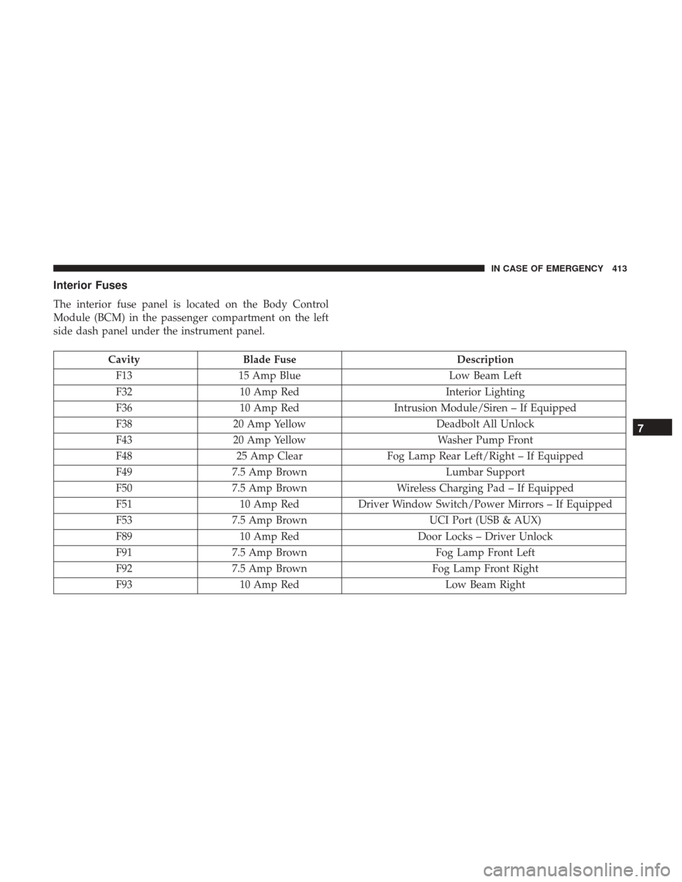
Interior Fuses
The interior fuse panel is located on the Body Control
Module (BCM) in the passenger compartment on the left
side dash panel under the instrument panel.
CavityBlade Fuse Description
F13 15 Amp Blue Low Beam Left
F32 10 Amp Red Interior Lighting
F36 10 Amp Red Intrusion Module/Siren – If Equipped
F38 20 Amp Yellow Deadbolt All Unlock
F43 20 Amp Yellow Washer Pump Front
F48 25 Amp Clear Fog Lamp Rear Left/Right – If Equipped
F49 7.5 Amp Brown Lumbar Support
F50 7.5 Amp Brown Wireless Charging Pad – If Equipped
F51 10 Amp RedDriver Window Switch/Power Mirrors – If Equipped
F53 7.5 Amp Brown UCI Port (USB & AUX)
F89 10 Amp Red Door Locks – Driver Unlock
F91 7.5 Amp Brown Fog Lamp Front Left
F92 7.5 Amp Brown Fog Lamp Front Right
F93 10 Amp Red Low Beam Right
7
IN CASE OF EMERGENCY 413
Page 468 of 615
6. Install the A/C air filter with the air filter positionindicators pointing in the same direction as removal.
CAUTION!
The cabin air filter is identified with an arrow to
indicate airflow direction through the filter. Failure to
properly install the filter will result in the need to
replace it more often.
7. Install the passenger side hush panel under the dash panel and console closeout.
Refer to the “Maintenance Plan” for the proper mainte-
nance intervals.
Body Lubrication
Locks and all body pivot points, including such items as
seat tracks, door hinge pivot points and rollers, liftgate,
tailgate, decklid, sliding doors and hood hinges, should be
lubricated periodically with a lithium based grease, such as
MOPAR Spray White Lube to assure quiet, easy operation
and to protect against rust and wear. Prior to the applica-
tion of any lubricant, the parts concerned should be wiped
clean to remove dust and grit; after lubricating excess oil
and grease should be removed. Particular attention should
also be given to hood latching components to ensure
proper function. When performing other underhood ser-
vices, the hood latch, release mechanism and safety catch
should be cleaned and lubricated.
The external lock cylinders should be lubricated twice a
year, preferably in the Fall and Spring. Apply a small
amount of a high quality lubricant, such as MOPAR Lock
Cylinder Lubricant directly into the lock cylinder.
466 SERVICING AND MAINTENANCE
Page 532 of 615
Buttons On The Faceplate
Buttons on the faceplate are located below the Uconnect
system in the center of the instrument panel. In addition,
there is a Scroll/Enter control knob located on the right
side of the Climate Controls in the center of the instrument
panel. Turn the control knob to scroll through menus and
change settings (i.e., 30, 60, 90), push the center of the
control knob one or more times to select or change a setting
(i.e., ON, OFF).
Your Uconnect system may also have Screen Off and Back
buttons located below the Uconnect system.
Push the Screen Off button to turn off the Uconnect
touchscreen. Push the Screen Off button a second time to
turn the touchscreen on.
Push the Back button to exit out of a Menu or certain
option on the Uconnect system.
Buttons On The Touchscreen
Buttons on the touchscreen are accessible on the Uconnect
display.
Customer Programmable Features/Personal
Settings — Uconnect 5.0 Settings
Push the SETTINGS or the MORE button on the faceplate,
then the “Settings” button on the touchscreen (if equipped)
to display the menu setting screen. In this mode the
Uconnect system allows you to access programmable fea-
tures that may be equipped such as Display, Voice, Clock &
Date, Safety & Assistance, Lights, Doors & Locks, Auto-On
Comfort, Engine Off Options, Compass Settings, Audio,
Phone/Bluetooth, Sirius Setup, Restore Settings, and Clear
Personal Data, Brakes and System Information.
NOTE:Only one category may be selected at a time.
When making a selection, press the button on the touch-
screen to enter the desired mode. Once in the desired
mode, press and release the preferred setting and make
your selection. Once the setting is complete, either press
the Back Arrow/Done button on the touchscreen or the
Back button on the faceplate to return to the previous menu
or press the “X” button on the touchscreen to close out of
the settings screen. Pressing the Up or Down Arrow
buttons on the right side of the screen will allow you to
toggle up or down through the available settings.
530 MULTIMEDIA
Page 540 of 615
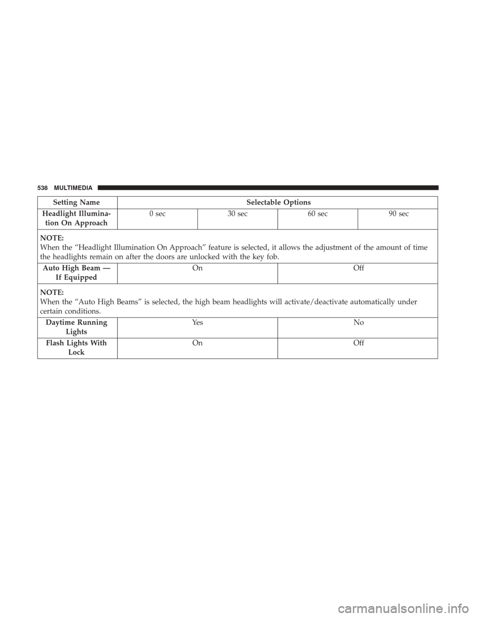
Setting NameSelectable Options
Headlight Illumina- tion On Approach 0 sec
30 sec 60 sec 90 sec
NOTE:
When the “Headlight Illumination On Approach” feature is selected, it allows the adjustment of the amount of time
the headlights remain on after the doors are unlocked with the key fob. Auto High Beam — If Equipped On
Off
NOTE:
When the “Auto High Beams” is selected, the high beam headlights will activate/deactivate automatically under
certain conditions. Daytime Running Lights Ye s
N o
Flash Lights With Lock On
Off
538 MULTIMEDIA