warning light JEEP CHEROKEE 2017 KL / 5.G Manual PDF
[x] Cancel search | Manufacturer: JEEP, Model Year: 2017, Model line: CHEROKEE, Model: JEEP CHEROKEE 2017 KL / 5.GPages: 615, PDF Size: 5.72 MB
Page 384 of 615
CAUTION!(Continued)
•Ensure that the Electric Park Brake is released, and
remains released, while being towed.
• Do not use a bumper-mounted clamp-on tow bar on
your vehicle. The bumper face bar will be damaged.
Shifting Into NEUTRAL (N)
WARNING!
You or others could be injured or killed if you leave the
vehicle unattended with the power transfer unit in the
NEUTRAL (N) position without first fully engaging
the parking brake. The NEUTRAL (N) position disen-
gages both the front and rear driveshafts from the
powertrain and will allow the vehicle to roll, even if
the transmission is in PARK. The parking brake
should always be applied when the driver is not in the
vehicle.
Use the following procedure to shift the 4WD system into
NEUTRAL (N).
CAUTION!
It is necessary to follow these steps to be certain that the
power transfer unit is fully in NEUTRAL (N) before
recreational towing to prevent damage to internal parts.
1. Bring the vehicle to a complete stop and shift the transmission to PARK.
2. Turn the engine OFF.
3. Turn the ignition to the ON/RUN mode, but do not start the engine.
4. Press and hold the brake pedal.
5. Shift the transmission into NEUTRAL.
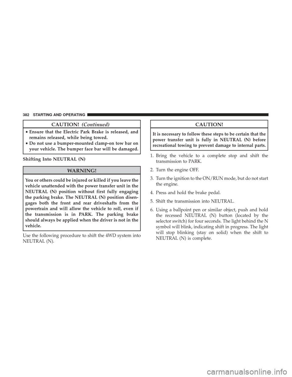
6. Using a ballpoint pen or similar object, push and hold the recessed NEUTRAL (N) button (located by the
selector switch) for four seconds. The light behind the N
symbol will blink, indicating shift in progress. The light
will stop blinking (stay on solid) when the shift to
NEUTRAL (N) is complete.
382 STARTING AND OPERATING
Page 389 of 615
Driving In Snow, Mud And Sand
In heavy snow, when pulling a load, or for additional
control at slower speeds, shift the transmission to a low
gear and shift the 4WD system to the appropriate terrain
mode, using 4WD LOW if necessary. Refer to “Four-Wheel
Drive Operation” in “Starting And Operating” for further
information. Do not shift to a lower gear than necessary to
maintain headway. Over-revving the engine can spin the
wheels and traction will be lost.
Avoid abrupt downshifts on icy or slippery roads because
engine braking may cause skidding and loss of control.
Hill Climbing
NOTE:Before attempting to climb a hill, determine the
conditions at the crest and/or on the other side.
Before climbing a steep hill, shift the transmission to a
lower gear and shift the 4WD System to 4WD LOW. Use
first gear and 4WD LOW for very steep hills.
NOTE: Brakes should be applied at increased slippage, but
before coming to a stop to avoid digging into the loose
surface and rendering the operator of the vehicle stuck/
immobile. If you stall or begin to lose headway
while climbing a
steep hill, allow your vehicle to come to a stop and
immediately apply the brakes. Once stopped, shift to
REVERSE. Back slowly down the hill allowing the com-
pression braking of the engine to help regulate your speed.
If the brakes are required to control vehicle speed, apply
them lightly and avoid locking or skidding the tires.
WARNING!
If the engine stalls or you lose headway or cannot
make it to the top of a steep hill or grade, never attempt
to turn around. To do so may result in tipping and
rolling the vehicle. Always back straight down a hill in
REVERSE gear carefully. Never back down a hill in
NEUTRAL using only the brake.
NOTE: Remember, never drive diagonally across a hill -
drive straight up or down.
If the wheels start to slip as you approach the crest of a hill,
ease off the accelerator and maintain headway by turning
the front wheels slowly left and right. This may provide a
fresh “bite” into the surface and may provide traction to
complete the climb.6
STARTING AND OPERATING 387
Page 396 of 615
WARNING!(Continued)
•The 9-1-1 Call system is embedded into the vehicle’s
electrical system. Do not add aftermarket electrical
equipment to the vehicle’s electrical system. This
may prevent your vehicle from sending a signal to
initiate an emergency call. To avoid interference that
can cause the 9-1-1 Call system to fail, never add
aftermarket equipment (e.g., two-way mobile radio,
CB radio, data recorder, etc.) to your vehicle’s electri-
cal system or modify the antennas on your vehicle. IF
YOUR VEHICLE LOSES BATTERY POWER FOR
ANY REASON (INCLUDING DURING OR AFTER
AN ACCIDENT), THE UCONNECT FEATURES,
APPS AND SERVICES, AMONG OTHERS, WILL
NOT OPERATE.
• Modifications to any part of the 9-1-1 Call system
could cause the air bag system to fail when you need
it. You could be injured if the air bag system is not
there to help protect you. 9-1-1 Call System Limitations
Vehicles sold in Canada and Mexico
DO NOThave 9-1-1
Call system capabilities.
9-1-1 or other emergency line operators in Canada and
Mexico may not answer or respond to 9-1-1 system calls.
If the 9-1-1 Call system detects a malfunction, any of the
following may occur at the time the malfunction is de-
tected, and at the beginning of each ignition cycle:
• The Rearview Mirror light located between the ASSIST
and 9-1-1 buttons will continuously be illuminated red.
• The Device Screen will display the following message
“Vehicle device requires service. Please contact your
dealer.”
• An In-Vehicle Audio message will state “Vehicle device
requires service. Please contact your dealer.”
394 IN CASE OF EMERGENCY
Page 397 of 615
WARNING!
•Ignoring the Rearview Mirror light could mean you
will not have 9-1-1 Call services. If the Rearview
Mirror light is illuminated, have an authorized
dealer service the 9-1-1 Call system immediately.
• The Occupant Restraint Control module turns on the
air bag Warning Light on the instrument panel if a
malfunction in any part of the system is detected. If
the Air Bag Warning Light is illuminated, have an
authorized dealer service the Occupant Restraint
Control system immediately.
Even if the 9-1-1 Call system is fully functional, factors
beyond FCA US LLC’s control may prevent or stop the
9-1-1 Call system operation. These include, but are not
limited to, the following factors:
• Delayed accessories mode is active.
• The ignition is in the OFF position.
• The vehicle’s electrical systems are not intact.
• The 9-1-1 Call system software and/or hardware are
damaged during a crash. •
The vehicle battery loses power or becomes discon-
nected during a vehicle crash.
• 1X(voice/data) or 3G(data) network and/or Global Po-
sitioning Satellite signals are unavailable or obstructed.
• Equipment malfunction at the 9-1-1 operator facility.
• Operator error by the 9-1-1 operator.
• 1X(voice/data) or 3G(data) network congestion.
• Weather.
• Buildings, structures, geographic terrain, or tunnels.
WARNING!
ALWAYS obey traffic laws and pay attention to the
road. Some Uconnect Access services, including 9-1-1
and Assist, will NOT work without an operable
1X(voice/data) or 3G(data) network connection.
7
IN CASE OF EMERGENCY 395
Page 400 of 615
Replacing Exterior Bulbs
Bi-Xenon High Intensity Discharge (HID)
Headlamps — If Equipped
The headlamps contain a type of high voltage discharge
light source. High voltage can remain in the circuit even
with the headlamp switch off. Because of this, you should
not attempt to service a HID headlamp light source your-
self. If an HID headlamp light source fails, take your
vehicle to an authorized dealer for service.
NOTE:On vehicles equipped with HID headlamps, when
the headlamps are turned on, there is a blue hue to the
lights. This diminishes and becomes more white after
approximately 10 seconds, as the system charges.
WARNING!
A transient high voltage occurs at the bulb sockets of
HID headlamps when the headlamp switch is turned
ON. It may cause serious electrical shock or electrocu-
tion if not serviced properly. See your authorized
dealer for service.
Bi-Halogen Headlamps
1. Remove the 3 hex head screws from the wheel liner.
2. Pull the exterior edge of the liner towards the tire to gain access to the headlamp bulb cap.
3.
Firmly grasp the cap and rotate it counterclockwise to
unlock it.
4. Firmly grasp the bulb and connector assembly and rotate counterclockwise to remove from the housing.
5. Disconnect the bulb from the electrical connector and then connect the replacement bulb.
CAUTION!
Do not touch the new bulb with your fingers. Oil
contamination will severely shorten bulb life. If the
bulb comes in contact with any oily surface, clean the
bulb with rubbing alcohol.
6. Install the bulb and connector assembly into the head- lamp housing and rotate clockwise to lock it in place.
7. Install the bulb cap in the headlamp housing and rotate clockwise to lock it in place.
8. Install the 3 hex head screws into the wheel liner.
398 IN CASE OF EMERGENCY
Page 423 of 615
9. Install the wheel bolts with the threaded end of thewheel bolt toward the wheel. Lightly tighten the wheel
bolts.
WARNING!
To avoid the risk of forcing the vehicle off the jack, do
not tighten the wheel nuts fully until the vehicle has
been lowered. Failure to follow this warning may
result in serious injury.
10. Lower the vehicle to the ground by turning the jack handle counterclockwise.
11. Finish tightening the wheel bolts. Push down on the wrench while at the end of the handle for increased
leverage. Tighten the wheel bolts in a star pattern until
each wheel bolt has been tightened twice. Refer to
“Torque Specifications” in “Technical Specifications”
for the proper lug bolt torque. If in doubt about the
correct tightness, have them checked with a torque
wrench by your authorized dealer or at a service
station. 12. Securely stow the jack, tools, chocks and flat tire.
Assembled Jack
7
IN CASE OF EMERGENCY 421
Page 424 of 615
WARNING!
A loose tire or jack thrown forward in a collision or
hard stop could endanger the occupants of the vehicle.
Always stow the jack parts and the spare tire in the
places provided. Have the deflated (flat) tire repaired
or replaced immediately.
Road Tire Installation
1. Mount the road tire on the axle.
2. Install the remaining wheel bolts with the threaded endof the wheel bolt toward the wheel. Lightly tighten the
wheel bolts.
WARNING!
To avoid the risk of forcing the vehicle off the jack, do
not tighten the wheel nuts fully until the vehicle has
been lowered. Failure to follow this warning may
result in serious injury.
3. Lower the vehicle to the ground by turning the jack handle counterclockwise.
4. Finish tightening the wheel bolts. Push down on the wrench while at the end of the handle for increased
leverage. Tighten the wheel bolts in a star pattern until
each wheel bolt has been tightened twice. Refer to
“Torque Specifications” in “Technical Specifications” for
the proper lug bolt torque. If in doubt about the correct
tightness, have them checked with a torque wrench by
your authorized dealer or service station.
Stowed Tire, Jack And Chock
422 IN CASE OF EMERGENCY
Page 434 of 615
WARNING!
Do not attempt jump-starting if the battery is frozen. It
could rupture or explode and cause personal injury.
CAUTION!
Do not use a portable battery booster pack or any other
booster source with a system voltage greater than 12
Volts or damage to the battery, starter motor, alternator
or electrical system may occur.
Preparations For Jump-Start
The battery in your vehicle is located in the front of the
engine compartment, behind the left headlight assembly.
NOTE:The positive battery post is covered with a protec-
tive cap. Lift up on the cap to gain access to the positive
battery post.WARNING!
•Take care to avoid the radiator cooling fan whenever
the hood is raised. It can start anytime the ignition
switch is ON. You can be injured by moving fan blades.
•Remove any metal jewelry such as rings, watch bands
and bracelets that could make an inadvertent electrical
contact. You could be seriously injured.
•Batteries contain sulfuric acid that can burn your skin or
eyes and generate hydrogen gas which is flammable
and explosive. Keep open flames or sparks away from
the battery.
Positive Battery Post
432 IN CASE OF EMERGENCY
Page 480 of 615
•Maintain engine coolant (antifreeze) concentration at a
minimum of 50% OAT coolant (conforming to
MS.90032) and distilled water for proper corrosion pro-
tection of your engine which contains aluminum com-
ponents.
• Make sure that the coolant expansion bottle overflow
hoses are not kinked or obstructed.
• Keep the front of the radiator clean. If your vehicle is
equipped with air conditioning, keep the front of the
condenser clean.
• Do not change the thermostat for Summer or Winter
operation. If replacement is ever necessary, install ONLY
the correct type thermostat. Other designs may result in
unsatisfactory engine coolant (antifreeze) performance,
poor gas mileage, and increased emissions.
Brake System
In order to assure brake system performance, all brake
system components should be inspected periodically. Refer
to the “Maintenance Plan” in this section for the proper
maintenance intervals.
WARNING!
Riding the brakes can lead to brake failure and possi-
bly a collision. Driving with your foot resting or riding
on the brake pedal can result in abnormally high brake
temperatures, excessive lining wear, and possible
brake damage. You would not have your full braking
capacity in an emergency.
Fluid Level Check — Brake Master Cylinder
The fluid level of the master cylinder should be checked
whenever the vehicle is serviced, or immediately if the
brake system warning light is on. If necessary, add fluid to
bring level to the full mark on the side of the reservoir of
the brake master cylinder. Be sure to clean the top of the
master cylinder area before removing cap. With disc
brakes, fluid level can be expected to fall as the brake pads
wear. Brake fluid level should be checked when pads are
replaced. If the brake fluid is abnormally low, check system
for leaks.
Refer to “Fluids And Lubricants” in “Technical Specifica-
tions” for further information.
478 SERVICING AND MAINTENANCE
Page 496 of 615
WARNING!
Tires and the spare tire should be replaced after six
years, regardless of the remaining tread. Failure to
follow this warning can result in sudden tire failure.
You could lose control and have a collision resulting in
serious injury or death.
Keep dismounted tires in a cool, dry place with as little
exposure to light as possible. Protect tires from contact with
oil, grease, and gasoline.
Replacement Tires
The tires on your new vehicle provide a balance of many
characteristics. They should be inspected regularly for
wear and correct cold tire inflation pressures. The manu-
facturer strongly recommends that you use tires equivalent
to the originals in size, quality and performance when
replacement is needed. Refer to the paragraph on “Tread
Wear Indicator”. Refer to the Tire and Loading Information
placard or the Vehicle Certification Label for the size
designation of your tire. The Load Index and Speed
Symbol for your tire will be found on the original equip-
ment tire sidewall. See the Tire Sizing Chart example found in the “Tire Safety Information” section of this manual for
more information relating to the Load Index and Speed
Symbol of a tire.
It is recommended to replace the two front tires or two rear
tires as a pair. Replacing just one tire can seriously affect
your vehicle’s handling. If you ever replace a wheel, make
sure that the wheel’s specifications match those of the
original wheels.
It is recommended you contact your authorized tire dealer
or original equipment dealer with any questions you may
have on tire specifications or capability. Failure to use
equivalent replacement tires may adversely affect the
safety, handling, and ride of your vehicle.
WARNING!
•
Do not use a tire, wheel size, load rating, or speed
rating other than that specified for your vehicle.
Some combinations of unapproved tires and wheels
may change suspension dimensions and perfor-
mance characteristics, resulting in changes to steer-
ing, handling, and braking of your vehicle. This can
cause unpredictable handling and stress to steering
(Continued)
494 SERVICING AND MAINTENANCE