audio JEEP CHEROKEE 2017 KL / 5.G User Guide
[x] Cancel search | Manufacturer: JEEP, Model Year: 2017, Model line: CHEROKEE, Model: JEEP CHEROKEE 2017 KL / 5.GPages: 615, PDF Size: 5.72 MB
Page 134 of 615
The instrument cluster display menu items consist of the
following:
•Speedometer
• Vehicle Info
• Driver Assist — If Equipped
• Fuel Economy
• Trip
• Stop/Start (If Equipped)
• Audio
• Messages
• Screen Setup
• Speed Warning The system allows the driver to select information by
pushing the following buttons mounted on the steering
wheel:
Instrument Cluster Display Control Buttons
132 GETTING TO KNOW YOUR INSTRUMENT PANEL
Page 139 of 615
Trip Info
Push and release theupordownarrow button
until the Trip Menu Icon is highlighted in the instru-
ment cluster display. Toggle the left
orrightar-
row button to select Trip A or Trip B. The Trip informa-
tion will display the following:
• Distance – Shows the total distance (mi or km) traveled
for Trip A or Trip B since the last reset.
• Average Fuel Economy – Shows the average fuel
economy (MPG, L/100 km, or km/L) of Trip A or Trip B
since the last reset.
• Elapsed Time – Shows the total elapsed time of travel
since Trip A or Trip B has been reset.
Hold the OKbutton to reset feature information.
Stop/Start – If Equipped
Push and release the upordownarrow button
until the Stop/Start icon is highlighted in the instru-
ment cluster display. Push and release the right
ar-
row button to display the Stop/Start status. Audio
Push and release the
upordownarrow button
until the Audio Icon is highlighted in the instrument
cluster display.
Stored Messages
Push and release the upordownarrow button
until the Messages Menu Icon is highlighted in the
instrument cluster display. This feature shows the num-
ber of stored warning messages. Pushing the left
or
right
arrow button will allow you to scroll through
the stored messages.
Screen Setup
Push and release the upordownarrow button
until the Screen Setup Menu Icon/Title is highlighted in
the instrument cluster display. Push and release the OK
button to enter the sub-menus and follow the prompts
on the screen as needed. The Screen Setup feature
allows you to change what information is displayed in
the instrument cluster as well as the location that
information is displayed. 4
GETTING TO KNOW YOUR INSTRUMENT PANEL 137
Page 141 of 615
Favorite Menus — Equipped
•Speedometer
• Vehicle Info
• Terrain (show/hide)
• Driver Assist (show/hide)
• Fuel Economy (show/hide)
• Trip Info (show/hide)
• Stop/Start
• Audio (show/hide)
• Messages
• Screen Setup
• Speed Warning (show/hide)
The menu with (show/hide) means user can press OK
button to choose show or hide this menu on the instrument
cluster display.Gear Shift Indicator (GSI) — If Equipped
The Gear Shift Indicator (GSI) system is enabled on ve-
hicles with manual shifting mode. The GSI provides the
driver with a visual indication within the instrument
cluster display when the recommended gear shift point has
been reached. This indication notifies the driver that
changing gears will allow a reduction in fuel consumption.
When the shift up indicator is shown on the display, the
GSI is advising the driver to engage a higher gear.
The GSI indicator in the instrument cluster display remains
illuminated until the driver changes gear, or the driving
conditions return to a situation where changing gear is not
required to improve fuel consumption.
Speed Warning — If Equipped
Push and release the upordownarrow button
until the Speed Warning Menu icon/title is highlighted
in the instrument cluster display. Push and release the
OK button to enter speed warning. Use the up
or
down
arrow button to select a desired speed, then
push and release the OKbutton to set the speed. The
Speed Warning telltale will display in the instrument
cluster display, and a chime will sound with a pop up
warning message when the set speed is exceeded. 4
GETTING TO KNOW YOUR INSTRUMENT PANEL 139
Page 142 of 615
Battery Saver On/Battery Saver Mode Message —
Electrical Load Reduction Actions — If Equipped
This vehicle is equipped with an Intelligent Battery Sensor
(IBS) to perform additional monitoring of the electrical
system and status of the vehicle battery.
In cases when the IBS detects charging system failure, or
the vehicle battery conditions are deteriorating, electrical
load reduction actions will take place to extend the driving
time and distance of the vehicle. This is done by reducing
power to or turning off non-essential electrical loads.
Load reduction is only active when the engine is running.
It will display a message if there is a risk of battery
depletion to the point where the vehicle may stall due to
lack of electrical supply, or will not restart after the current
drive cycle.
When load reduction is activated, the message “Battery
Saver On” or “Battery Saver Mode” will appear in the
instrument cluster display.
These messages indicate the vehicle battery has a low state
of charge and continues to lose electrical charge at a rate
that the charging system cannot sustain.NOTE:
•
The charging system is independent from load reduc-
tion. The charging system performs a diagnostic on the
charging system continuously.
• If the Battery Charge Warning Light is on it may indicate
a problem with the charging system. Refer to “Battery
Charge Warning Light” in ”Warning And Indicator
Lights And Messages” located in ”Getting To Know
Your Instrument Panel” for further information.
The electrical loads that may be switched off (if equipped),
and vehicle functions which can be effected by load
reduction:
• Heated Seat/Vented Seats/Heated Wheel
• Heated/Cooled Cup Holders — If Equipped
• Rear Defroster And Heated Mirrors
• HVAC System
• 115V AC Power Inverter System
• Audio and Telematics System
140 GETTING TO KNOW YOUR INSTRUMENT PANEL
Page 143 of 615
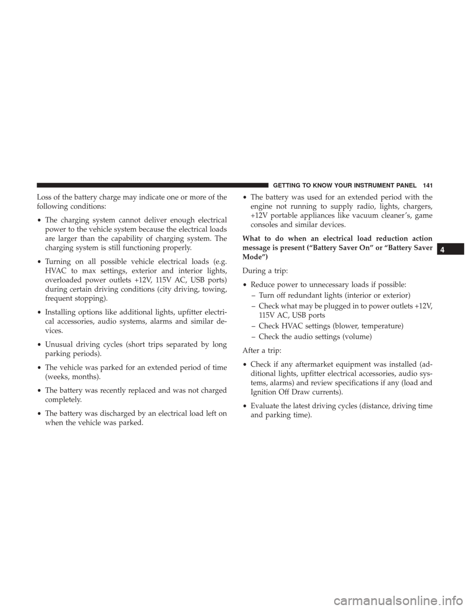
Loss of the battery charge may indicate one or more of the
following conditions:
•The charging system cannot deliver enough electrical
power to the vehicle system because the electrical loads
are larger than the capability of charging system. The
charging system is still functioning properly.
• Turning on all possible vehicle electrical loads (e.g.
HVAC to max settings, exterior and interior lights,
overloaded power outlets +12V, 115V AC, USB ports)
during certain driving conditions (city driving, towing,
frequent stopping).
• Installing options like additional lights, upfitter electri-
cal accessories, audio systems, alarms and similar de-
vices.
• Unusual driving cycles (short trips separated by long
parking periods).
• The vehicle was parked for an extended period of time
(weeks, months).
• The battery was recently replaced and was not charged
completely.
• The battery was discharged by an electrical load left on
when the vehicle was parked. •
The battery was used for an extended period with the
engine not running to supply radio, lights, chargers,
+12V portable appliances like vacuum cleaner ’s, game
consoles and similar devices.
What to do when an electrical load reduction action
message is present (“Battery Saver On” or “Battery Saver
Mode”)
During a trip:
• Reduce power to unnecessary loads if possible:
– Turn off redundant lights (interior or exterior)
– Check what may be plugged in to power outlets +12V, 115V AC, USB ports
– Check HVAC settings (blower, temperature)
– Check the audio settings (volume)
After a trip:
• Check if any aftermarket equipment was installed (ad-
ditional lights, upfitter electrical accessories, audio sys-
tems, alarms) and review specifications if any (load and
Ignition Off Draw currents).
• Evaluate the latest driving cycles (distance, driving time
and parking time).
4
GETTING TO KNOW YOUR INSTRUMENT PANEL 141
Page 187 of 615
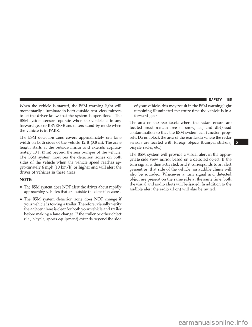
When the vehicle is started, the BSM warning light will
momentarily illuminate in both outside rear view mirrors
to let the driver know that the system is operational. The
BSM system sensors operate when the vehicle is in any
forward gear or REVERSE and enters stand-by mode when
the vehicle is in PARK.
The BSM detection zone covers approximately one lane
width on both sides of the vehicle 12 ft (3.8 m). The zone
length starts at the outside mirror and extends approxi-
mately 10 ft (3 m) beyond the rear bumper of the vehicle.
The BSM system monitors the detection zones on both
sides of the vehicle when the vehicle speed reaches ap-
proximately 6 mph (10 km/h) or higher and will alert the
driver of vehicles in these areas.
NOTE:
•
The BSM system does NOT alert the driver about rapidly
approaching vehicles that are outside the detection zones.
• The BSM system detection zone does NOT change if
your vehicle is towing a trailer. Therefore, visually verify
the adjacent lane is clear for both your vehicle and trailer
before making a lane change. If the trailer or other object
(i.e., bicycle, sports equipment) extends beyond the side of your vehicle, this may result in the BSM warning light
remaining illuminated the entire time the vehicle is in a
forward gear.
The area on the rear fascia where the radar sensors are
located must remain free of snow, ice, and dirt/road
contamination so that the BSM system can function prop-
erly. Do not block the area of the rear fascia where the radar
sensors are located with foreign objects (bumper stickers,
bicycle racks, etc.)
The BSM system will provide a visual alert in the appro-
priate side view mirror based on a detected object. If the
turn signal is then activated, and it corresponds to an alert
present on that side of the vehicle, an audible chime will
also be sounded. Whenever a turn signal and detected
object are present on the same side at the same time, both
the visual and audio alerts will be issued. In addition to the
audible alert the radio (if on) will also be muted.
5
SAFETY 185
Page 319 of 615
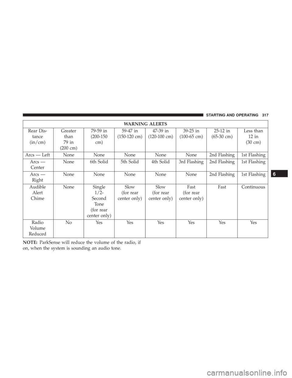
WARNING ALERTS
Rear Dis- tance
(in/cm) Greater
than
79 in
(200 cm) 79-59 in
(200-150 cm) 59-47 in
(150-120 cm)
47-39 in
(120-100 cm)
39-25 in
(100-65 cm) 25-12 in
(65-30 cm) Less than
12 in
(30 cm)
Arcs — Left None None None None None
2nd Flashing1st Flashing
Arcs — Center None 6th Solid 5th Solid 4th Solid
3rd Flashing2nd Flashing1st Flashing
Arcs — Right None None None None None
2nd Flashing1st Flashing
Audible Alert
Chime None Single
1/2-
Second Tone
(for rear
center only) Slow
(for rear
center only) Slow
(for rear
center only) Fast
(for rear
center only) Fast Continuous
Radio
Volume
Reduced No
Yes YesYesYes Yes Yes
NOTE: ParkSense will reduce the volume of the radio, if
on, when the system is sounding an audio tone.6
STARTING AND OPERATING 317
Page 328 of 615
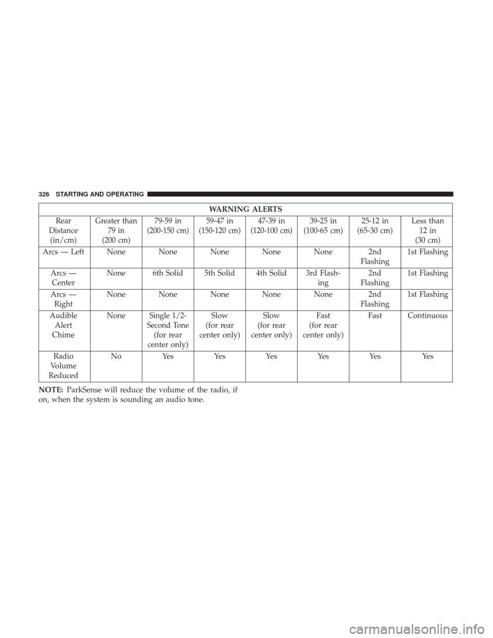
WARNING ALERTS
Rear
Distance (in/cm)
Greater than 79 in
(200 cm)79-59 in
(200-150 cm)
59-47 in
(150-120 cm)
47-39 in
(120-100 cm)
39-25 in
(100-65 cm) 25-12 in
(65-30 cm) Less than
12 in
(30 cm)
Arcs — Left None None None None None 2nd Flashing1st Flashing
Arcs — Center None 6th Solid 5th Solid 4th Solid 3rd Flash-
ing2nd
Flashing 1st Flashing
Arcs — Right None None None None None 2nd
Flashing1st Flashing
Audible Alert
Chime None
Single 1/2-
Second Tone
(for rear
center only) Slow
(for rear
center only) Slow
(for rear
center only) Fast
(for rear
center only) Fast Continuous
Radio
Volume
Reduced No
Yes YesYesYesYes Yes
NOTE: ParkSense will reduce the volume of the radio, if
on, when the system is sounding an audio tone.
326 STARTING AND OPERATING
Page 331 of 615
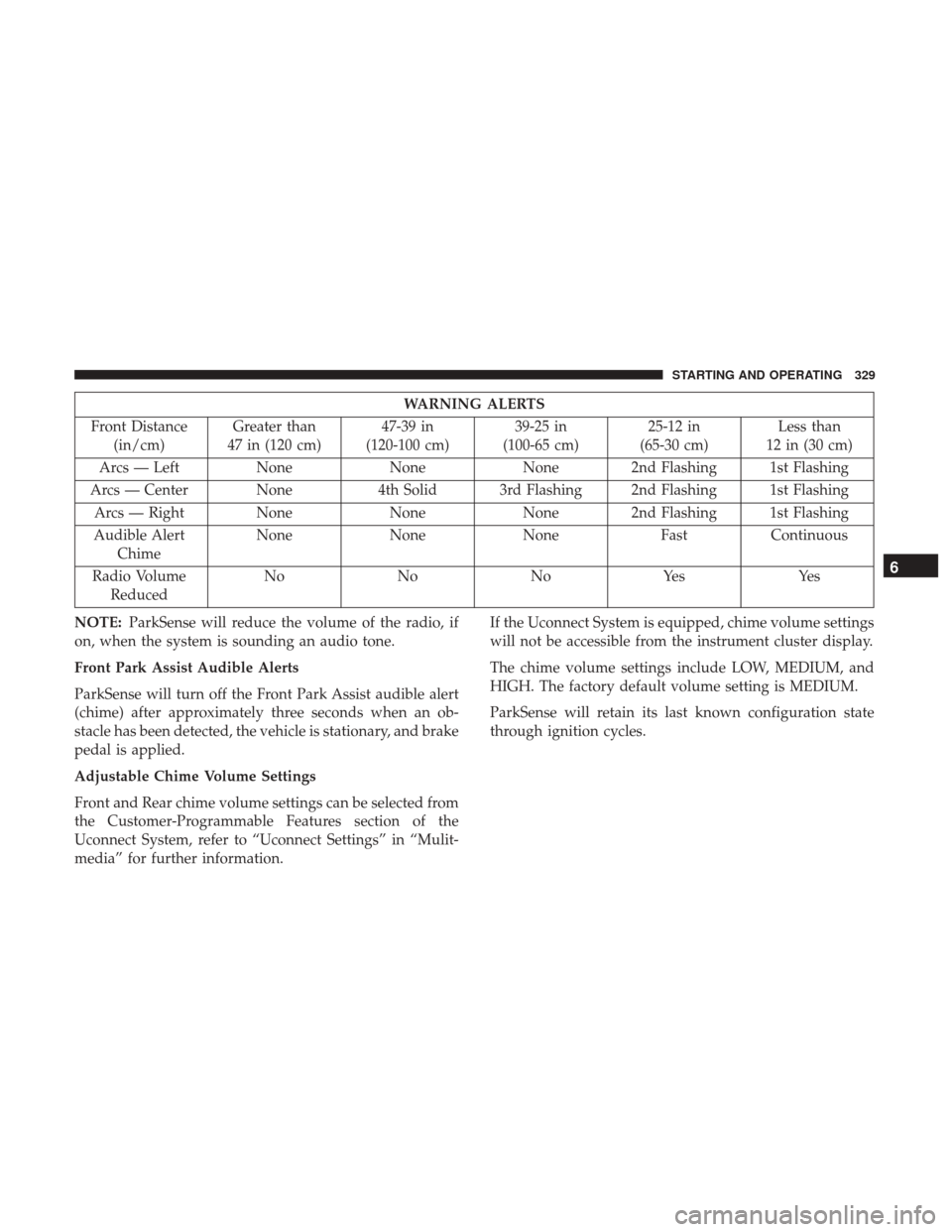
WARNING ALERTS
Front Distance (in/cm) Greater than
47 in (120 cm) 47-39 in
(120-100 cm) 39-25 in
(100-65 cm) 25-12 in
(65-30 cm) Less than
12 in (30 cm)
Arcs — Left NoneNoneNone 2nd Flashing 1st Flashing
Arcs — Center None 4th Solid 3rd Flashing 2nd Flashing 1st Flashing
Arcs — Right None NoneNone 2nd Flashing 1st Flashing
Audible Alert Chime None
NoneNone FastContinuous
Radio Volume Reduced No
NoNoYes Yes
NOTE: ParkSense will reduce the volume of the radio, if
on, when the system is sounding an audio tone.
Front Park Assist Audible Alerts
ParkSense will turn off the Front Park Assist audible alert
(chime) after approximately three seconds when an ob-
stacle has been detected, the vehicle is stationary, and brake
pedal is applied.
Adjustable Chime Volume Settings
Front and Rear chime volume settings can be selected from
the Customer-Programmable Features section of the
Uconnect System, refer to “Uconnect Settings” in “Mulit-
media” for further information. If the Uconnect System is equipped, chime volume settings
will not be accessible from the instrument cluster display.
The chime volume settings include LOW, MEDIUM, and
HIGH. The factory default volume setting is MEDIUM.
ParkSense will retain its last known configuration state
through ignition cycles.
6
STARTING AND OPERATING 329
Page 394 of 615
NOTE:
•Your vehicle may be transmitting data as authorized by
the subscriber.
• The 9–1–1 and ASSIST buttons will only function if you
are connected to an operable 1X(voice/data) or 3G(data)
network. Other Uconnect services will only be operable
if your Uconnect Access service is active and you are
connected to an operable 1X(voice/data) or 3G(data)
network.
ASSIST Call
The ASSIST Button is used to automatically connect you to
any one of the following support centers:
• Roadside Assistance – If you get a flat tire, or need a tow,
just push the ASSIST button and you’ll be connected to
someone who can help. Roadside Assistance will know
what vehicle you’re driving and its location. Additional
fees may apply for roadside Assistance.
•
Uconnect Access Customer Care – In-vehicle support for
Uconnect Access and Uconnect Access Via Mobile fea-
tures.
• Vehicle Customer Care – Total support for all other
vehicle issues. 9-1-1 Call
1. Push the 9-1-1 Call button on the Rearview Mirror.
NOTE:
In case the 9-1-1 Call button is pushed in error,
there will be a 10 second delay before the 9-1-1 Call system
initiates a call to a 9-1-1 operator. To cancel the 9-1-1 Call
connection, push the 9-1-1 Call button on the Rearview
Mirror or press the cancellation button on the Device
Screen. Termination of the 9-1-1 Call will turn off the green
LED light on the Rearview Mirror.
2. The LED light located between the ASSIST and 9-1-1 buttons on the Rearview Mirror will turn green once a
connection to a 9-1-1 operator has been made.
3.
Once a connection between the vehicle and a 9-1-1 operator
is made, the 9-1-1 Call system may transmit the following
important vehicle information to a 9-1-1 operator:
• Indication that the occupant placed a 9-1-1 Call.
• The vehicle brand.
• The last known GPS coordinates of the vehicle.
4. You should be able to speak with the 9-1-1 operator through the vehicle audio system to determine if addi-
tional help is needed.
392 IN CASE OF EMERGENCY