buttons JEEP CHEROKEE 2017 KL / 5.G User Guide
[x] Cancel search | Manufacturer: JEEP, Model Year: 2017, Model line: CHEROKEE, Model: JEEP CHEROKEE 2017 KL / 5.GPages: 615, PDF Size: 5.72 MB
Page 40 of 615
If a rear door is locked, it cannot be opened from inside the
vehicle without first unlocking the door. The door may be
unlocked manually by raising the lock knob.
Keyless Enter-N-Go — Passive Entry
The Passive Entry system is an enhancement to the vehi-
cle’s Remote Keyless Entry system and a feature of Keyless
Enter-N-Go — Passive Entry. This feature allows you to
lock and unlock the vehicle’s door(s) and fuel door without
having to push the key fob lock or unlock buttons.
NOTE:
•Passive Entry may be programmed ON/OFF; refer to
“Uconnect Settings” in “Multimedia” for further infor-
mation.
• If wearing gloves on your hands, or if it has been raining
on the Passive Entry door handle, the unlock sensitivity
can be affected, resulting in a slower response time.
• If the vehicle is unlocked by Passive Entry and no door
is opened within 60 seconds, the vehicle will re-lock and
if equipped will arm the security alarm. To Unlock From The Driver’s Side
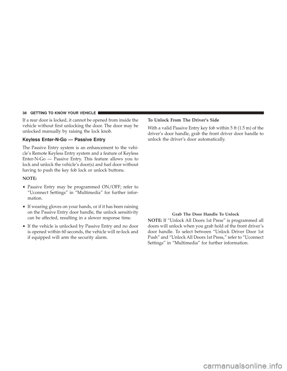
With a valid Passive Entry key fob within 5 ft (1.5 m) of the
driver’s door handle, grab the front driver door handle to
unlock the driver’s door automatically.
NOTE:
If “Unlock All Doors 1st Press” is programmed all
doors will unlock when you grab hold of the front driver ’s
door handle. To select between “Unlock Driver Door 1st
Push” and “Unlock All Doors 1st Press,” refer to “Uconnect
Settings” in “Multimedia” for further information.
Grab The Door Handle To Unlock
38 GETTING TO KNOW YOUR VEHICLE
Page 52 of 615
Driver Memory Seat — If Equipped
This feature allows the driver to store up to two different
memory profiles, for easy recall through a memory switch.
Each memory profile contains desired position settings for
the driver seat and side mirrors and a set of desired radio
station presets.
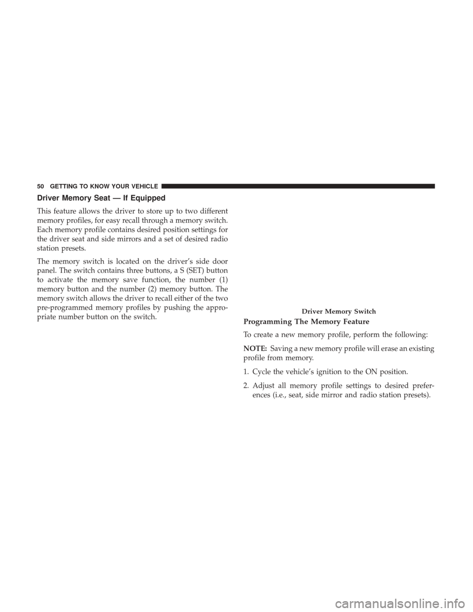
The memory switch is located on the driver’s side door
panel. The switch contains three buttons, a S (SET) button
to activate the memory save function, the number (1)
memory button and the number (2) memory button. The
memory switch allows the driver to recall either of the two
pre-programmed memory profiles by pushing the appro-
priate number button on the switch.
Programming The Memory Feature
To create a new memory profile, perform the following:
NOTE:Saving a new memory profile will erase an existing
profile from memory.
1. Cycle the vehicle’s ignition to the ON position.
2. Adjust all memory profile settings to desired prefer- ences (i.e., seat, side mirror and radio station presets).
Driver Memory Switch
50 GETTING TO KNOW YOUR VEHICLE
Page 54 of 615
NOTE:Your key fob can be unlinked to your memory
settings by pushing the SET (S) button, followed by push-
ing the unlock button on the key fob within 10 seconds.
Memory Position Recall
NOTE: The vehicle must be in PARK to recall memory
positions. If a recall is attempted when the vehicle is not in
PARK, a message will display in the instrument cluster
display.
• To recall the memory settings for driver one, push
memory button number 1 or the unlock button on the
key fob linked to memory position 1.
• To recall the memory settings for driver two, push
memory button number 2 or the unlock button on the
key fob linked to memory position 2.
A recall can be cancelled by pushing any of the memory
buttons (S, 1, or 2) during a recall. When a recall is
cancelled, the driver seat will stop moving. A delay of one
second will occur before another recall can be selected.
Easy Entry/Exit Seat
This feature provides automatic driver seat positioning to
enhance driver mobility when entering and exiting the
vehicle. The distance the driver seat moves depends on where you
have the driver seat positioned when you cycle the vehi-
cle’s ignition to the OFF position.
•
When you cycle the vehicle’s ignition to the OFF posi-
tion, the driver seat will move about 2.4 inches (60 mm)
rearward if the driver seat position is greater than or
equal to 2.7 inches (67.7 mm) forward of the rear stop.
The seat will return to its previously set position when
you cycle the vehicle’s ignition to the ACC or RUN
position.
• The Easy Entry/Easy Exit feature is disabled when the
driver seat position is less than 0.9 of an inch (22.7 mm)
forward of the rear stop. At this position, there is no
benefit to the driver by moving the seat for Easy Exit or
Easy Entry.
Each stored memory setting will have an associated Easy
Entry and Easy Exit position.
NOTE: The Easy Entry/Exit feature is not enabled when
the vehicle is delivered from the factory. The Easy Entry/
Exit feature is enabled (or later disabled) through the
programmable features in the Uconnect system. Refer to
“Uconnect Settings/Customer Programmable Features” in
“Mulitmedia” for further information.
52 GETTING TO KNOW YOUR VEHICLE
Page 55 of 615
Front Heated Seats — If Equipped
The front heated seats control buttons are located within
the Uconnect system. You can gain access to the control
buttons through the climate screen or the controls screen.
•Press the heated seat button
once to turn the HI
setting ON.
• Press the heated seat buttona second time to turn
the LO setting ON.
• Press the heated seat buttona third time to turn the
heating elements OFF.
If the HI-level setting is selected, the system will automati-
cally switch to LO-level after approximately 60 minutes of
continuous operation. At that time, the display will change
from HI to LO, indicating the change. The LO-level setting
will turn OFF automatically after approximately 45 min-
utes.
NOTE: The engine must be running for the heated seats to
operate.
Vehicles Equipped With Remote Start
On models that are equipped with remote start, the heated
seats can be programmed to come on during a remote start. This feature can be programmed through the Uconnect
system. Refer to “Uconnect Settings” in “Multimedia” for
further information.
WARNING!
•
Persons who are unable to feel pain to the skin
because of advanced age, chronic illness, diabetes,
spinal cord injury, medication, alcohol use, exhaus-
tion or other physical condition must exercise care
when using the seat heater. It may cause burns even
at low temperatures, especially if used for long
periods of time.
• Do not place anything on the seat or seatback that
insulates against heat, such as a blanket or cushion.
This may cause the seat heater to overheat. Sitting in
a seat that has been overheated could cause serious
burns due to the increased surface temperature of the
seat.
Front Ventilated Seats — If Equipped
Located in the seat cushion and seat back are fans that
draw the air from the passenger compartment and move
air through fine perforations in the seat cover to help keep
the driver and front passenger cooler in higher ambient
temperatures. The fans operate at two speeds, HI and LO.
3
GETTING TO KNOW YOUR VEHICLE 53
Page 56 of 615
The front ventilated seats control buttons are located
within the Uconnect system. You can gain access to the
control buttons through the climate screen or the controls
screen.
•Press the ventilated seat button
once to choose HI.
•Press the ventilated seat buttona second time to
choose LO.
• Press the ventilated seat buttona third time to turn
the ventilated seat OFF.
NOTE: The engine must be running for the ventilated seats
to operate.
Vehicles Equipped With Remote Start
On models that are equipped with remote start, the venti-
lated seats can be programmed to come on during a remote
start.
This feature can be programmed through the Uconnect
system. Refer to “Uconnect Settings” in “Multimedia” for
further information.
HEAD RESTRAINTS
Head restraints are designed to reduce the risk of injury by
restricting head movement in the event of a rear impact.
Head restraints should be adjusted so that the top of the
head restraint is located above the top of your ear.
WARNING!
• All occupants, including the driver, should not oper-
ate a vehicle or sit in a vehicle’s seat until the head
restraints are placed in their proper positions in
order to minimize the risk of neck injury in the event
of a crash.
• Head restraints should never be adjusted while the
vehicle is in motion. Driving a vehicle with the head
restraints improperly adjusted or removed could
cause serious injury or death in the event of a
collision.
NOTE: Do not reverse the head restraints (making the rear
of the head restraint face forward) in an attempt to gain
additional clearance to the back of your head.
54 GETTING TO KNOW YOUR VEHICLE
Page 89 of 615
IconDescription
AUTO Button — If Equipped
Automatically controls the interior cabin temperature by adjusting airflow distribution and
amount. Performing this function will cause the system to switch between manual mode and
automatic modes. Refer to “Automatic Operation” for more information.
Front Defrost Button
Press and release to change the current airflow setting to Defrost mode. The indicator on the
touchscreen illuminates when this feature is on. Air comes from the windshield and side win-
dow demist outlets. When the defrost button is selected, the blower level will increase. Use De-
frost mode with maximum temperature settings for best windshield and side window defrosting
and defogging. Performing this function will cause the ATC to switch into manual mode. If the
front defrost mode is turned off the climate system will return the previous setting.
Rear Defrost Button
Push and release the Rear Defrost Control button to turn on the rear window defroster and the
heated outside mirrors (if equipped). An indicator will illuminate when the rear window de-
froster is on. The rear window defroster automatically turns off after 10 minutes.
Driver and Passenger Temperature UP and DOWN Buttons — If Equipped
Provides the passenger with independent temperature control. Push the up arrow button on the
faceplate, on the touchscreen, or press and slide the temperature bar towards the red arrow but-
ton on the touchscreen for warmer temperature settings. Push the down arrow button on the
faceplate, on the touchscreen, or press and slide the temperature bar towards the blue arrow
button on the touchscreen for cooler temperature settings. When the SYNC feature is active, the
passenger ’s temperature will move up with the driver ’s temperature, when it is increased.
3
GETTING TO KNOW YOUR VEHICLE 87
Page 90 of 615
IconDescription
SYNC Button — If Equipped
Press the Sync button on the touchscreen to toggle the Sync feature on/off. The Sync indicator is
illuminated when this feature is enabled. Sync is used to synchronize the passenger temperature
setting with the driver temperature setting. The Sync feature also synchronizes the rear passen-
gers’ temperature to the driver temperature setting. Changing the passenger temperature setting
while in Sync will automatically exit this feature.
Faceplate Knob
Touchscreen Buttons
Blower Control
Blower Control is used to regulate the amount of air forced through the climate system. There
are seven blower speeds available. Adjusting the blower will cause automatic mode to switch to
manual operation. The speeds can be selected using either the blower control knob on the face-
plate or the buttons on the touchscreen.
• Faceplate: The blower speed increases as you turn the blower control knob clockwise from
the lowest blower setting. The blower speed decreases as you turn the blower control knob
counterclockwise.
• Touchscreen: Use the small blower icon to reduce the blower setting and the large blower
icon to increase the blower setting. Blower can also be selected by pressing the blower bar
area between the icons.
Panel ModePanel Mode
Air comes from the outlets in the instrument panel. Each of these outlets can be individually
adjusted to direct the flow of air. The air vanes of the center outlets and outboard outlets can be
moved up and down or side to side to regulate airflow direction. There is a shut off wheel lo-
cated below the air vanes to shut off or adjust the amount of airflow from these outlets.
88 GETTING TO KNOW YOUR VEHICLE
Page 94 of 615
Automatic Temperature Control (ATC) —
If Equipped
Automatic Operation
1. Push the AUTO button on the faceplate, or the AUTObutton on the touchscreen on the Automatic Tempera-
ture Control (ATC) Panel.
2. Next, adjust the temperature you would like the system to maintain by adjusting the driver and passenger
temperature control buttons. Once the desired tempera-
ture is displayed, the system will achieve and automati-
cally maintain that comfort level.
3. When the system is set up for your comfort level, it is not necessary to change the settings. You will experience
the greatest efficiency by simply allowing the system to
function automatically.
NOTE:
• It is not necessary to move the temperature settings for
cold or hot vehicles. The system automatically adjusts
the temperature, mode, and blower speed to provide
comfort as quickly as possible. •
The temperature can be displayed in U.S. or Metric units
by selecting the US/Metric customer-programmable fea-
ture. Refer to the “Customer Programmable Features —
Uconnect System Settings” in “Multimedia” in your
Owner ’s Manual on jeep.com/en/owners/manuals for
further information.
To provide you with maximum comfort in the Automatic
mode during cold start-ups, the blower fan will remain on
low until the engine warms up. The blower will increase in
speed and transition into Auto mode.
Manual Operation Override
This system offers a full complement of manual override
features. The AUTO symbol in the front ATC display will
be turned off when the system is being used in the manual
mode.
NOTE: The system will not automatically sense the pres-
ence of fog, mist or ice on the windshield. DEFROST mode
must be manually selected to clear the windshield and side
glass.
92 GETTING TO KNOW YOUR VEHICLE
Page 108 of 615
WARNING!
During power operation, personal injury or cargo
damage may occur. Ensure the liftgate travel path is
clear. Make sure the liftgate is closed and latched
before driving away.
NOTE:
• The power liftgate buttons will not operate if the vehicle
is in gear or the vehicle speed is above 0 MPH (0 km/h).
•
The power liftgate will not operate in temperatures below
�22°F (�30°C) or temperatures above 150° F (65° C). Be
sure to remove any buildup of snow or ice from the
liftgate before pushing any of the power liftgate switches.
• If anything obstructs the power liftgate while it is
closing or opening, the liftgate will automatically re-
verse to the closed or open position, provided it meets
sufficient resistance.
• There are also pinch sensors attached to the side of the
liftgate. Light pressure anywhere along these strips will
cause the liftgate to return to the open position.
• If the liftgate is not fully open, push the liftgate button
on the key fob twice to operate the liftgate. •
If the electronic liftgate release is pushed while the
power liftgate is closing, the liftgate will reverse to the
full open position.
• If the electronic liftgate release is pushed while the
power liftgate is opening, the liftgate motor will disen-
gage to allow manual operation.
• If the power liftgate encounters multiple obstructions
within the same cycle, the system will automatically
stop and the liftgate must be opened or closed manually.
WARNING!
• Driving with the liftgate open can allow poisonous
exhaust gases into your vehicle. You and your pas-
sengers could be injured by these fumes. Keep the
liftgate closed when you are operating the vehicle.
• If you are required to drive with the liftgate open,
make sure that all windows are closed, and the
climate control blower switch is set at high speed. Do
not use the recirculation mode.
106 GETTING TO KNOW YOUR VEHICLE
Page 110 of 615
WARNING!(Continued)
•Place as much cargo as possible in front of the rear axle.
Too much weight or improperly placed weight over or
behind the rear axle can cause the vehicle to sway.
•Do not pile luggage or cargo higher than the top of the
seatback. This could impair visibility or become a
dangerous projectile in a sudden stop or accident.
Rear Storage Bins
The rear storage bins are located in the rear of the vehicle
on the sides of the load floor.
GARAGE DOOR OPENER — IF EQUIPPED
HomeLink replaces up to three hand-held transmitters that
operate devices such as garage door openers, motorized
gates, lighting or home security systems. The HomeLink
unit is powered by your vehicle’s 12 Volt battery.
The HomeLink buttons, located on the overhead console,
designate the three different HomeLink channels. The
HomeLink indicator is located above the center button.
NOTE: HomeLink is disabled when the Vehicle Security
Alarm is active.
Rear Storage Bins
HomeLink Buttons/Overhead Console
108 GETTING TO KNOW YOUR VEHICLE