BATTERY JEEP CHEROKEE 2018 Owner handbook (in English)
[x] Cancel search | Manufacturer: JEEP, Model Year: 2018, Model line: CHEROKEE, Model: JEEP CHEROKEE 2018Pages: 312, PDF Size: 4.91 MB
Page 124 of 312
The starter is allowed to crank for up to
30-second intervals. Waiting a few minutes
between such intervals will protect the starter
from overheating.
WARNING!
• Before exiting a vehicle, always come toa complete stop, then shift the auto-
matic transmission into PARK and apply
the parking brake.
• Always make sure the keyless ignition
node is in the OFF mode, key fob is
removed from the vehicle and vehicle is
locked.
• Never leave children alone in a vehicle,
or with access to an unlocked vehicle.
Leaving children in a vehicle unattended
is dangerous for a number of reasons. A
child or others could be seriously or
fatally injured. Children should be
warned not to touch the parking brake,
brake pedal or the gear selector.
• Do not leave the key fob in or near the
vehicle, or in a location accessible to
children, and do not leave the ignition of
a vehicle equipped with Keyless Enter-
WARNING!
N-Go in the ACC or ON/RUN mode. A
child could operate power windows,
other controls, or move the vehicle.
• Do not leave children or animals inside
parked vehicles in hot weather. Interior
heat build-up may cause serious injury
or death.
NOTE:
Engine start up in very low ambient tempera-
ture could result in evident white smoke. This
condition will disappear as the engine warms
up.
CAUTION!
The engine is allowed to crank as long as
30 seconds. If the engine fails to start
during this period, please wait at least two
minutes for the starter to cool before re-
peating start procedure.
Battery Blanket Usage
A battery loses 60% of its cranking power as
the battery temperature decreases to 0°F
(-18°C). For the same decrease in tempera-
ture, the engine requires twice as much
power to crank at the same RPM. The use of
battery blankets will greatly increase starting
capability at low temperatures. Suitable bat-
tery blankets are available from your autho-
rized Mopar dealer.
Normal Starting Procedure — Keyless
Enter-N-Go
Observe the instrument panel cluster lights
when starting the engine.
NOTE:
Normal starting of either a cold or a warm
engine is obtained without pumping or press-
ing the accelerator pedal.
1. Always apply the parking brake.
2. Press and hold the brake pedal while pushing the ENGINE START/STOP button
once.STARTING AND OPERATING
122
Page 138 of 312
tain operating conditions), the transmis-
sion may use second gear (rather than first
gear) during launches, to minimize wheel
slippage.
• Sport — This mode alters the transmis-
sion's automatic shift schedule for sportier
driving. Upshift speeds are increased to
make full use of available engine power.
NOTE:
SPORT mode is not available when 4WD LOW
is selected.
• Sand/Mud — Off-road calibration for use on
low traction surfaces such as mud, sand, or
wet grass. Driveline is maximized for trac-
tion. Some binding may be felt on less
forgiving surfaces. The electronic brake
controls are set to limit traction control
management of throttle and wheel spin.
• Rock — Off-road calibration only available
in 4WD LOW range. Traction based tuning
with improved steer-ability for use on high
traction off-road surfaces. Use for low
speed obstacles such as large rocks, deep
ruts, etc. NOTE:
• Rock mode is only available on the vehicles
equipped with the Off-Road package.
• Activate the Hill Descent Control or Selec Speed Control for steep downhill control.
See “Electronic Brake Control System” in
“Safety” for further information.
STOP/START SYSTEM —
IF EQUIPPED
The Stop/Start function was developed to
reduce fuel consumption. The system will
stop the engine automatically during a ve-
hicle stop if the required conditions are met.
Releasing the brake pedal or pressing the
accelerator pedal will automatically restart
the engine.
This vehicle has been upgraded with a Heavy
Duty Battery, Starter, as well as other engine
parts, to handle the Additional engine starts.
Automatic Mode
The Stop/Start feature is enabled after every
normal customer engine start. At that time,
the system will go into STOP/START READY
and if all other conditions are met, can go
into a STOP/START AUTOSTOP ACTIVE “Au-
tostop” mode.
To Activate The Autostop Mode, The Following
Must Occur:
• The system must be in STOP/STARTREADY state. A STOP/START READY mes-
sage will be displayed in the instrument
cluster display within the Stop/Start sec-
tion. Refer to “Warning Lights And Mes-
sages” in “Getting To Know Your Instru-
ment Panel” in your Owner’s Manual.
• The vehicle must be completely stopped.
• The gear selector must be in a forward gear and the brake pedal depressed.
The engine will shut down, the tachometer
will move to the zero position and the Stop/
Start telltale will illuminate indicating you
are in Autostop. Customer settings will be
maintained upon return to an engine running
condition.
STARTING AND OPERATING
136
Page 139 of 312
Refer to the “Stop/Start System” in the
“Starting And Operating” in your Owner’s
Manual.
Possible Reasons The Engine Does Not
Autostop
Prior to engine shut down, the system will
check many safety and comfort conditions to
see if they are fulfilled. Detailed information
about the operation of the Stop/Start system
may be viewed in the instrument cluster dis-
play Stop/Start Screen. In the following situ-
ations the engine will not stop:
• Driver’s seat belt is not buckled.
• Driver’s door is not closed.
• Battery temperature is too warm or cold.
• Battery charge is low.
• The vehicle is on a steep grade.
• Cabin heating or cooling is in process andan acceptable cabin temperature has not
been achieved.
• HVAC is set to full defrost mode at a high blower speed.
• HVAC set to MAX A/C. • Engine has not reached normal operating
temperature.
• The transmission is not in a forward or reverse gear.
• Hood is open.
• Vehicle is in 4LO transfer case mode (if equipped with 4WD).
• Brake pedal is not pressed with sufficient pressure with vehicle in DRIVE position.
Other Factors Which Can Inhibit Autostop In-
clude:
• Accelerator pedal input.
• Engine temp too high.
• 5 mph threshold not achieved from previ- ous AUTOSTOP.
• Steering angle beyond threshold.
• ACC is on and speed is set.
It may be possible for the vehicle to be driven
several times without the STOP/START sys-
tem going into a STOP/START READY state
under more extreme conditions of the items
listed above.
To Start The Engine While In Autostop
Mode
While in a forward gear, the engine will start
when the brake pedal is released or the
throttle pedal is depressed. The transmission
will automatically re-engage upon engine re-
start.
Conditions That Will Cause The Engine To Start
Automatically While In Autostop Mode:
• The transmission gear selector is moved out of DRIVE except in the PARK position.
• To maintain cabin temperature comfort.
• HVAC is set to full defrost mode.
• HVAC system temperature or fan speed is manually adjusted.
• Battery voltage drops too low.
• Low brake vacuum (e.g. after several brake pedal applications).
• STOP/START OFF switch is pushed.
• A STOP/START system error occurs.
• 4WD system is put into 4LO mode (if equipped with 4WD).
137
Page 141 of 312
Automatic Mode
The Stop/Start feature is enabled after every
normal customer engine start. It will remain
in STOP/START NOT READY until you drive
forward with a vehicle speed greater than
4 mph (7 km/h). At that time, the system will
go into STOP/START READY and if all other
conditions are met, can go into a STOP/
START AUTOSTOP ACTIVE “Autostop”
mode.
To Activate The Autostop Mode, The Following
Must Occur:
• The system must be in STOP/STARTREADY state. A STOP/START READY mes-
sage will be displayed in the instrument
cluster display within the Stop/Start sec-
tion. Refer to “Instrument Cluster Display”
in “Getting To Know Your Instrument
Panel” in your Owner’s information for fur-
ther details.
• The vehicle must be completely stopped.
• The gear selector must be in DRIVE and the brake pedal depressed (automatic trans-
mission) or the gear selector must be in
NEUTRAL and the clutch pedal must be
fully released (manual transmission). The engine will shut down, the tachometer
will move to the zero position and the Stop/
Start telltale will illuminate indicating you
are in Autostop. While in Autostop, the Cli-
mate Controls system may automatically ad-
just airflow to maintain cabin comfort. Cus-
tomer settings will be maintained upon return
to an engine running condition.
Possible Reasons The Engine Does Not
Autostop
Prior to engine shut down, the system will
check many safety and comfort conditions to
see if they are fulfilled. Detailed information
about the operation of the Stop/Start system
may be viewed in the instrument cluster
Stop/Start Screen. In the following situations
the engine will not stop:
• Driver’s seat belt is not buckled.
• Driver’s door is not closed.
• Battery temperature is too warm or cold.
• The vehicle is on a steep grade.
• Cabin heating or cooling is in process and
an acceptable cabin temperature has not
been achieved. • HVAC is set to full defrost mode at a high
blower speed.
• Engine has not reached normal operating temperature.
• Battery charge is low.
• The transmission is not in DRIVE (auto- matic transmission) or NEUTRAL (manual
transmission).
• Hood is open.
• Vehicle is in 4LO transfer case mode.
• Exhaust system regeneration in process.
Other Factors Which Can Inhibit Autostop In-
clude:
• Fuel level.
• Accelerator pedal input (automatic trans- mission only).
• Engine temperature too high.
It may be possible for the vehicle to be driven
several times without the STOP/START sys-
tem going into a STOP/START READY state
under more extreme conditions of the items
listed above.
139
Page 142 of 312
To Start The Engine While In Autostop
Mode
Automatic Transmission:
While in DRIVE, the engine will start when
the brake pedal is released or the throttle
pedal is depressed. The transmission will
automatically re-engage upon engine restart.
During this transition, the brakes will hold
the vehicle to avoid undesired vehicle move-
ment.
Manual Transmission:
When the gear selector is in NEUTRAL, the
engine will start when the clutch pedal is
pressed. The vehicle will go into STOP/
START SYSTEM NOT READY mode until the
vehicle speed is greater than 4 mph (7 km/h).
Conditions That Will Cause The Engine To Start
Automatically While In Autostop Mode:
• The transmission gear selector is movedfrom DRIVE to REVERSE or NEUTRAL.
• To maintain cabin temperature comfort.
• HVAC is set to full defrost mode. • Battery voltage drops too low.
• Low brake vacuum (e.g. after several brake
pedal applications).
• STOP/START OFF switch is pushed.
• 4WD system is put into 4LO mode.
• The emissions system requires it.
• A STOP/START system error occurs.
• HVAC system temperature or fan speed is manually adjusted.
Conditions That Force An Application Of The
Electric Park Brake While In Autostop Mode:
• The driver door is open and brake pedal released.
• The driver door is open and the driver seat belt is unbuckled.
• The engine hood has been opened.
• A STOP/START system error occurs.
If the Electric Park Brake is applied with the
engine off, the engine may require a manual
restart and the electric park brake may re-
quire a manual release (depress brake pedal
and push Electric Park Brake switch). Refer to “Instrument Cluster Display” in “Getting
To Know Your Instrument Panel” in your Own-
er’s Manual for further information.
To Manually Turn Off The Stop/Start
System
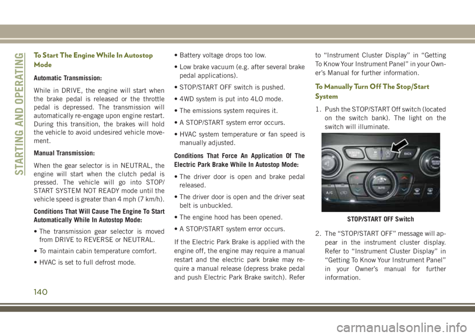
1. Push the STOP/START Off switch (located
on the switch bank). The light on the
switch will illuminate.
2. The “STOP/START OFF” message will ap- pear in the instrument cluster display.
Refer to “Instrument Cluster Display” in
“Getting To Know Your Instrument Panel”
in your Owner’s manual for further
information.
STOP/START OFF Switch
STARTING AND OPERATING
140
Page 162 of 312
HAZARD WARNING
FLASHERS
Control
The Hazard Warning flasher switch is located
on the switch bank just above the climate
controls.
Push the switch to turn on the Hazard Warn-
ing flasher. When the switch is activated, all
directional turn signals will flash on and off towarn oncoming traffic of an emergency. Push
the switch a second time to turn off the
Hazard Warning flashers.
This is an emergency warning system and it
should not be used when the vehicle is in
motion. Use it when your vehicle is disabled
and it is creating a safety hazard for other
motorists.
When you must leave the vehicle to seek
assistance, the Hazard Warning flashers will
continue to operate even though the ignition
is placed in the OFF position. NOTE:
With extended use, the Hazard Warning
flashers may discharge the battery.
BULB REPLACEMENT
Replacement Bulbs
Interior Bulbs
Bulb Number
Cargo Lamp TL212–2
Overhead Console Lamp PLW214–2A Reading Lamp WL212–2
IN CASE OF EMERGENCY
160
Page 166 of 312
FUSES
WARNING!
• When replacing a blown fuse, always usean appropriate replacement fuse with
the same amp rating as the original fuse.
Never replace a fuse with another fuse of
higher amp rating. Never replace a
blown fuse with metal wires or any other
material. Do not place a fuse inside a
circuit breaker cavity or vice versa. Fail-
ure to use proper fuses may result in
serious personal injury, fire and/or prop-
erty damage.
• Before replacing a fuse, make sure that
the ignition is off and that all the other
services are switched off and/or disen-
gaged.
• If the replaced fuse blows again, contact
an authorized dealer.
WARNING!
• If a general protection fuse for safetysystems (air bag system, braking sys-
tem), power unit systems (engine sys-
tem, transmission system) or steering
system blows, contact an authorized
dealer.
General Information
The fuses protect electrical systems against
excessive current.
When a device does not work, you must check
the fuse element inside the blade fuse for a
break/melt.
Also, please be aware that when using power
outlets for extended periods of time with the
engine off may result in vehicle battery dis-
charge.
Underhood Fuses
The Power Distribution Center is located in
the engine compartment near the battery.
This center contains cartridge fuses, mini-
fuses and relays. A label that identifies each
component is printed on the inside of the
cover.
IN CASE OF EMERGENCY
164
Page 171 of 312
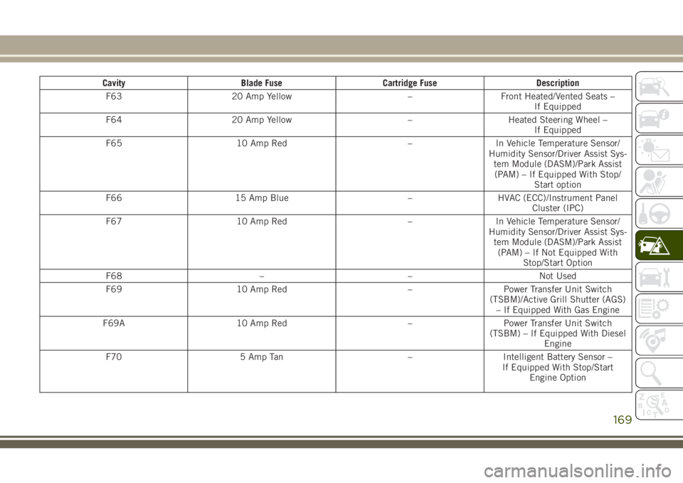
CavityBlade Fuse Cartridge Fuse Description
F63 20 Amp Yellow –Front Heated/Vented Seats –
If Equipped
F64 20 Amp Yellow –Heated Steering Wheel –
If Equipped
F65 10 Amp Red –In Vehicle Temperature Sensor/
Humidity Sensor/Driver Assist Sys- tem Module (DASM)/Park Assist(PAM) – If Equipped With Stop/ Start option
F66 15 Amp Blue –HVAC (ECC)/Instrument Panel
Cluster (IPC)
F67 10 Amp Red –In Vehicle Temperature Sensor/
Humidity Sensor/Driver Assist Sys- tem Module (DASM)/Park Assist(PAM) – If Not Equipped With Stop/Start Option
F68 ––Not Used
F69 10 Amp Red –Power Transfer Unit Switch
(TSBM)/Active Grill Shutter (AGS) – If Equipped With Gas Engine
F69A 10 Amp Red –Power Transfer Unit Switch
(TSBM) – If Equipped With Diesel Engine
F70 5 Amp Tan –Intelligent Battery Sensor –
If Equipped With Stop/Start Engine Option
169
Page 188 of 312
JUMP STARTING
If your vehicle has a discharged battery, it can
be jump started using a set of jumper cables
and a battery in another vehicle or by using a
portable battery booster pack. Jump starting
can be dangerous if done improperly, so please
follow the procedures in this section carefully.
NOTE:
When using a portable battery booster pack,
follow the manufacturer’s operating instruc-
tions and precautions.
WARNING!
Do not attempt jump starting if the battery
is frozen. It could rupture or explode and
cause personal injury.
CAUTION!
Do not use a portable battery booster pack
or any other booster source with a system
voltage greater than 12 Volts or damage to
the battery, starter motor, alternator or
electrical system may occur.
Preparations For Jump Start
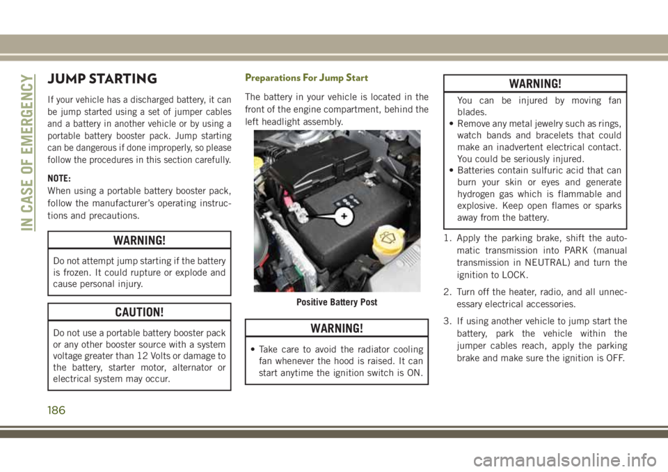
The battery in your vehicle is located in the
front of the engine compartment, behind the
left headlight assembly.
WARNING!
• Take care to avoid the radiator coolingfan whenever the hood is raised. It can
start anytime the ignition switch is ON.
WARNING!
You can be injured by moving fan
blades.
• Remove any metal jewelry such as rings,
watch bands and bracelets that could
make an inadvertent electrical contact.
You could be seriously injured.
• Batteries contain sulfuric acid that can
burn your skin or eyes and generate
hydrogen gas which is flammable and
explosive. Keep open flames or sparks
away from the battery.
1. Apply the parking brake, shift the auto- matic transmission into PARK (manual
transmission in NEUTRAL) and turn the
ignition to LOCK.
2. Turn off the heater, radio, and all unnec- essary electrical accessories.
3. If using another vehicle to jump start the battery, park the vehicle within the
jumper cables reach, apply the parking
brake and make sure the ignition is OFF.
Positive Battery Post
IN CASE OF EMERGENCY
186
Page 189 of 312
WARNING!
Do not allow vehicles to touch each other
as this could establish a ground connec-
tion and personal injury could result.
Jump Starting Procedure
WARNING!
Failure to follow this jump starting proce-
dure could result in personal injury or
property damage due to battery explosion.
CAUTION!
Failure to follow these procedures could
result in damage to the charging system of
the booster vehicle or the discharged ve-
hicle.
Connecting The Jumper Cables
1. Connect the positive (+)end of the jumper
cable to the positive (+)post of the dis-
charged vehicle. 2. Connect the opposite end of the positive
(+) jumper cable to the positive (+)post of
the booster battery.
3. Connect the negative (-)end of the jumper
cable to the negative (-)post of the
booster battery.
4. Connect the opposite end of the negative (-)jumper cable to a good engine ground
(exposed metal part of the discharged
vehicle’s engine) away from the battery
and the fuel injection system.
WARNING!
Do not connect the jumper cable to the
negative (-) post of the discharged battery.
The resulting electrical spark could cause
the battery to explode and could result in
personal injury. Only use the specific
ground point, do not use any other exposed
metal parts.
5. Start the engine in the vehicle that has the booster battery, let the engine idle for a
few minutes, and then start the engine in
the vehicle with the discharged battery. 6. Once the engine is started, remove the
jumper cables in the reverse sequence:
Disconnecting The Jumper Cables
1. Disconnect the negative (-)end of the
jumper cable from the engine ground of
the vehicle with the discharged battery.
2. Disconnect the opposite end of the nega- tive (-)jumper cable from the negative (-)
post of the booster battery.
3. Disconnect the positive (+)end of the
jumper cable from the positive (+)post of
the booster battery.
4. Disconnect the opposite end of the posi- tive (+)jumper cable from the positive (+)
post of the vehicle with the discharged
battery.
If frequent jump starting is required to start
your vehicle, you should have the battery and
charging system inspected at an authorized
dealer.
187