ESP JEEP CHEROKEE 2018 Owner handbook (in English)
[x] Cancel search | Manufacturer: JEEP, Model Year: 2018, Model line: CHEROKEE, Model: JEEP CHEROKEE 2018Pages: 312, PDF Size: 4.91 MB
Page 78 of 312
Dynamic Steering Torque (DST)
Dynamic Steering Torque is a feature of the
ESC and Electric Power Steering (EPS) mod-
ules that provides torque at the steering
wheel for certain driving conditions in which
the ESC module is detecting vehicle instabil-
ity. The torque that the steering wheel re-
ceives is only meant to help the driver realize
optimal steering behavior in order to reach/
maintain vehicle stability. The only notifica-
tion the driver receives that the feature is
active is the torque applied to the steering
wheel.
NOTE:
The DST feature is only meant to help the
driver realize the correct course of action
through small torques on the steering wheel,
which means the effectiveness of the DST
feature is highly dependent on the driver’s
sensitivity and overall reaction to the applied
torque. It is very important to realize that this
feature will not steer the vehicle, meaning
the driver is still responsible for steering the
vehicle.
Hill Descent Control (HDC) — If Equipped
HDC is intended for low speed off road driv-
ing while in 4WD Low Range. HDC maintains
vehicle speed while descending hills during
various driving situations. HDC controls ve-
hicle speed by actively controlling the brakes.
HDC Has Three States:
1. Off (feature is not enabled and will notactivate).
2. Enabled (feature is enabled and ready but activation conditions are not met, or
driver is actively overriding with brake or
throttle application).
3. Active (feature is enabled and actively controlling vehicle speed).
Enabling HDC
HDC is enabled by pushing the HDC switch,
but the following conditions must also be met
to enable HDC:
• Driveline is in 4WD Low Range.
• Vehicle speed is below 5 mph (8 km/h).
• Parking brake is released.
• Driver door is closed. Activating HDC
Once HDC is enabled it will activate auto-
matically if driven down a grade of sufficient
magnitude. The set speed for HDC is select-
able by the driver, and can be adjusted by
using the gear shift +/-. The following sum-
marizes the HDC set speeds:
HDC Target Set Speeds
• P = No set speed. HDC may be enabled but
will not activate.
• R = 0.6 mph (1 km/h)
• N = 1.2 mph (2 km/h)
• D = 0.6 mph (1 km/h)
• 1st = 0.6 mph (1 km/h)
• 2nd = 1.2 mph (2 km/h)
• 3rd = 1.8 mph (3 km/h)
• 4th = 2.5 mph (4 km/h)
• 5th = 3.1 mph (5 km/h)
• 6th = 3.7 mph (6 km/h)
• 7th = 4.3 mph (7 km/h)
• 8th = 5.0 mph (8 km/h)
• 9th = 5.6 mph (9 km/h) – If Equipped
SAFETY
76
Page 79 of 312
NOTE:
During HDC the +/- shifter input is used for
HDC target speed selection, but will not af-
fect the gear chosen by the transmission.
When actively controlling HDC the transmis-
sion will shift appropriately for the driver-
selected set speed and corresponding driving
conditions.
Driver Override
The driver may override HDC activation with
throttle or brake application at anytime.
Deactivating HDC
HDC will be deactivated but remain available
if any of the following conditions occur:
• Driver overrides HDC set speed with throttleor brake application.
• Vehicle speed exceeds 20 mph (32 km/h) but remains below 40 mph (64 km/h).
• Vehicle is on a downhill grade of insuffi- cient magnitude, is on level ground, or is on
an uphill grade.
• Vehicle is shifted to park. Disabling HDC
HDC will be deactivated and disabled if any
of the following conditions occur:
• The driver pushes the HDC switch.
• The driveline is shifted out of 4WD Low
Range.
• The parking brake is applied.
• Driver door opens.
• The vehicle is driven greater than 20 mph (32 km/h) for greater than 70 seconds.
• The vehicle is driven greater than 40 mph (64 km/h) (HDC exits immediately).
• HDC detects excessive brake temperature.
Feedback To The Driver
The instrument cluster has an HDC icon and
the HDC switch has an LED icon, which offers
feedback to the driver about the state HDC is
in.
• The cluster icon and switch lamp will illu- minate and remain on solid when HDC is
enabled or activated. This is the normal
operating condition for HDC. • The cluster icon and switch lamp will flash
for several seconds then extinguish when
the driver pushes the HDC switch but en-
able conditions are not met.
• The cluster icon and switch lamp will flash for several seconds then extinguish when
HDC disables due to excess speed.
• The cluster icon and switch lamp will flash when HDC deactivates due to overheated
brakes. The flashing will stop and HDC will
activate again once the brakes have cooled
sufficiently.
WARNING!
HDC is only intended to assist the driver in
controlling vehicle speed when descend-
ing hills. The driver must remain attentive
to the driving conditions and is responsible
for maintaining a safe vehicle speed.
Selec Speed Control (SSC) — If Equipped
SSC is intended for off road driving in 4WD
Low Range only. SSC maintains vehicle
speed by actively controlling engine torque
and brakes.
77
Page 80 of 312
SSC has three states:
1. Off (feature is not enabled and will notactivate).
2. Enabled (feature is enabled and ready but activation conditions are not met, or
driver is actively overriding with brake or
throttle application).
3. Active (feature is enabled and actively controlling vehicle speed).
Enabling SSC
SSC is enabled by pushing the SSC switch,
but the following conditions must also be met
to enable SSC:
• Driveline is in 4WD Low Range.
• Vehicle speed is below 5 mph (8 km/h).
• Parking brake is released.
• Driver door is closed.
• Driver is not applying throttle.
Activating SSC
Once SSC is enabled it will activate automati-
cally once the following conditions are met:
• Driver releases throttle. • Driver releases brake.
• Transmission is in any selection other than
P.
• Vehicle speed is below 20 mph (32 km/h).
The set speed for SSC is selectable by the
driver, and can be adjusted by using the gear
shift +/-. Additionally, the SSC set speed may
be reduced when climbing a grade and the
level of set speed reduction depends on the
magnitude of grade. The following summa-
rizes the SSC set speeds:
SSC Target Set Speeds
• 1st = .6 mph (1 km/h)
• 2nd = 1.2 mph (2 km/h)
• 3rd = 1.8 mph (3 km/h)
• 4th = 2.5 mph (4 km/h)
• 5th = 3.1 mph (5 km/h)
• 6th = 3.7 mph (6 km/h)
• 7th = 4.3 mph (7 km/h)
• 8th = 5 mph (8 km/h)
• 9th = 5.6 mph (9 km/h) – If Equipped
• REVERSE = .6 mph (1 km/h) • NEUTRAL = 1.2 mph (2 km/h)
• PARK = SSC remains enabled but not
active
NOTE:
• During SSC the +/- shifter input is used for SSC target speed selection but will not
affect the gear chosen by the transmission.
While actively controlling SSC the trans-
mission will shift appropriately for the
driver-selected set speed and correspond-
ing driving conditions.
• SSC performance is influenced by the Ter- rain Select mode. This difference may be
notable to the driver and may be perceived
as a varying level of aggressiveness.
Driver Override:
The driver may override SSC activation with
throttle or brake application at any time.
Deactivating SSC
SSC will be deactivated but remain available
if any of the following conditions occur:
• Driver overrides SSC set speed with throttle or brake application.
SAFETY
78
Page 81 of 312
• Vehicle speed exceeds 20 mph (32 km/h)but remains below 40 mph (64 km/h).
• Vehicle is shifted to PARK.
Disabling SSC
SSC will deactivate and be disabled if any of
the following conditions occur:
• The driver pushes the SSC switch.
• The driveline is shifted out of 4WD Low Range.
• The parking brake is applied.
• Driver door opens.
• The vehicle is driven greater than 20 mph (32 km/h) for greater than 70 seconds.
• The vehicle is driven greater than 40 mph (64 km/h) (SSC exits immediately).
Feedback To The Driver:
The instrument cluster has an SSC icon and
the SSC switch has an LED which offer feed-
back to the driver about the state SSC is in. • The cluster icon and switch lamp will illu-
minate and remain on solid when SSC is
enabled or activated. This is the normal
operating condition for SSC.
• The cluster icon and switch lamp will flash for several seconds then extinguish when
the driver pushes the SSC switch but en-
able conditions are not met.
• The cluster icon and switch lamp will flash for several seconds then extinguish when
SSC disables due to excess speed.
• The cluster icon and switch lamp will flash then extinguish when SSC deactivates due
to overheated brakes.
WARNING!
SSC is only intended to assist the driver in
controlling vehicle speed when driving in
off road conditions. The driver must re-
main attentive to the driving conditions
and is responsible for maintaining a safe
vehicle speed.
AUXILIARY DRIVING
SYSTEMS
Blind Spot Monitoring
The Blind Spot Monitoring (BSM) system
uses two radar-based sensors, located inside
the rear bumper fascia, to detect highway
licensable vehicles (automobiles, trucks, mo-
torcycles etc.) that enter the blind spot zones
from the rear/front/side of the vehicle.
The BSM detection zone covers approxi-
mately one lane width on both sides of the
vehicle 12 ft (3.8 m). The zone length starts
at the outside rear view mirror and extends
approximately 10 ft (3 m) beyond the rear
bumper of the vehicle. The BSM system
monitors the detection zones on both sides of
the vehicle when the vehicle speed reaches
approximately 6 mph (10 km/h) or higher and
will alert the driver of vehicles in these areas.
79
Page 82 of 312
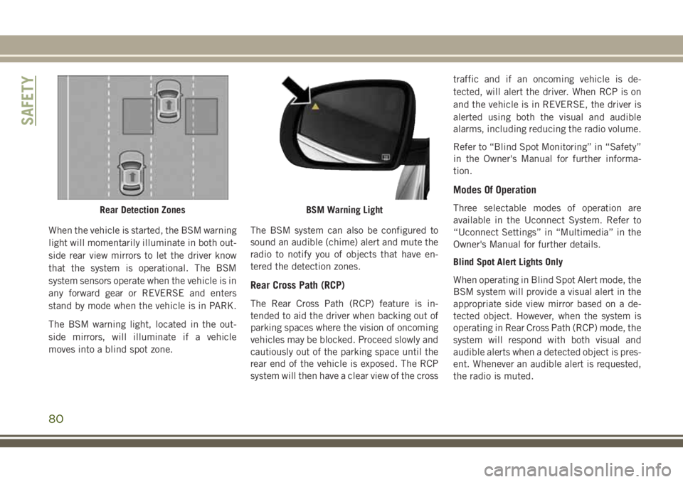
When the vehicle is started, the BSM warning
light will momentarily illuminate in both out-
side rear view mirrors to let the driver know
that the system is operational. The BSM
system sensors operate when the vehicle is in
any forward gear or REVERSE and enters
stand by mode when the vehicle is in PARK.
The BSM warning light, located in the out-
side mirrors, will illuminate if a vehicle
moves into a blind spot zone.The BSM system can also be configured to
sound an audible (chime) alert and mute the
radio to notify you of objects that have en-
tered the detection zones.
Rear Cross Path (RCP)
The Rear Cross Path (RCP) feature is in-
tended to aid the driver when backing out of
parking spaces where the vision of oncoming
vehicles may be blocked. Proceed slowly and
cautiously out of the parking space until the
rear end of the vehicle is exposed. The RCP
system will then have a clear view of the cross traffic and if an oncoming vehicle is de-
tected, will alert the driver. When RCP is on
and the vehicle is in REVERSE, the driver is
alerted using both the visual and audible
alarms, including reducing the radio volume.
Refer to “Blind Spot Monitoring” in “Safety”
in the Owner's Manual for further informa-
tion.
Modes Of Operation
Three selectable modes of operation are
available in the Uconnect System. Refer to
“Uconnect Settings” in “Multimedia” in the
Owner's Manual for further details.
Blind Spot Alert Lights Only
When operating in Blind Spot Alert mode, the
BSM system will provide a visual alert in the
appropriate side view mirror based on a de-
tected object. However, when the system is
operating in Rear Cross Path (RCP) mode, the
system will respond with both visual and
audible alerts when a detected object is pres-
ent. Whenever an audible alert is requested,
the radio is muted.Rear Detection ZonesBSM Warning Light
SAFETY
80
Page 83 of 312
Blind Spot Alert Lights/Chime
When operating in Blind Spot Alert Lights/
Chime mode, the BSM system will provide a
visual alert in the appropriate side view mirror
based on a detected object. If the turn signal
is then activated, and it corresponds to an
alert present on that side of the vehicle, an
audible chime will also be sounded. When-
ever a turn signal and detected object are
present on the same side at the same time,
both the visual and audible alerts will be
issued. In addition to the audible alert, the
radio (if on) will also be muted.
NOTE:
Whenever an audible alert is requested by the
BSM system, the radio is also muted.
When the system is in RCP, the system shall
respond with both visual and audible alerts
when a detected object is present. Whenever
an audible alert is requested, the radio is also
muted. Turn/hazard signal status is ignored;
the RCP state always requests the chime.Blind Spot Alert Off
When the BSM system is turned off, there will
be no visual or audible alerts from either the
BSM or RCP systems.
NOTE:
The BSM system will store the current oper-
ating mode when the vehicle is shut off. Each
time the vehicle is started the previously
stored mode will be recalled and used.
Forward Collision Warning (FCW)
The Forward Collision Warning (FCW) system
provides the driver with audible and visual
warnings within the instrument cluster display
to warn the driver when it detects a potential
frontal collision. The warnings are intended to
provide the driver with enough time to react,
avoid or mitigate the potential collision.
NOTE:
FCW monitors the information from the for-
ward looking sensors, as well as the Elec-
tronic Brake Controller (EBC), to calculate
the probability of a forward collision. When
the system determines that a forward colli-
sion is probable, the driver will be provided
with audible and visual warnings.Turning FCW On Or Off
The FCW button is located on the switch
panel below the Uconnect display.
• To turn the FCW system off, push the for-
ward collision button once to turn the sys-
tem OFF.
• To turn the FCW system back on, push the forward collision button again to turn the
system on.
NOTE:
• The default status of FCW is “on”, this allows the system to warn you of a possible
collision with the vehicle in front of you.
• Changing the FCW status to “off” prevents the system from warning you of a possible
collision with the vehicle in front of you. If
FCW is set to off, “FCW OFF” will appear in
the instrument cluster display.
Changing FCW Status
The FCW feature has two settings and can be
changed within the Uconnect System
Screen:
• Far
• Near
81
Page 84 of 312
Far
The far setting provides warnings for poten-
tial collisions more distant in front of the
vehicle, allowing the driver to have the most
reaction time to avoid a collision.
More cautious drivers that do not mind fre-
quent warnings may prefer this setting.
NOTE:
This setting gives you the most reaction time.
Near
Changing the FCW status to the “Near” set-
ting, allows the system to warn you of a
potential frontal collision when you are much
closer.
This setting provides less reaction time than
the “Far” setting, which allows for a more
dynamic driving experience.
More dynamic or aggressive drivers that want
to avoid frequent warnings may prefer this
setting.NOTE:
Changing the Active Braking status to off
prevents the system from providing autono-
mous braking, or additional brake support if
the driver is not braking adequately in the
event of a potential frontal collision. Active
braking can be turned off in the Uconnect
controls settings.
Refer to your Owner's Manual for further
information.
WARNING!
Forward Collision Warning (FCW) is not
intended to avoid a collision on its own,
nor can FCW detect every type of potential
collision. The driver has the responsibility
to avoid a collision by controlling the ve-
hicle via braking and steering. Failure to
follow this warning could lead to serious
injury or death.
Tire Pressure Monitor System (TPMS)
The Tire Pressure Monitor System (TPMS)
will warn the driver of a low tire pressure
based on the vehicle recommended cold
placard pressure.
The tire pressure will vary with temperature
by approximately 1 psi (7 kPa) for every 12°F
(6.5°C). This means that when the outside
temperature decreases, the tire pressure will
decrease. Tire pressure should always be set
based on cold inflation tire pressure. This is
defined as the tire pressure after the vehicle
has not been driven for at least three hours, or
driven less than 1 mile (1.6 km) after a three
hour period. The cold tire inflation pressure
must not exceed the maximum inflation pres-
sure molded into the tire sidewall. Refer to
“Tires” in “Servicing And Maintenance” for
information on how to properly inflate the
vehicle’s tires. The tire pressure will also
increase as the vehicle is driven. This is
normal and there should be no adjustment for
this increased pressure.
SAFETY
82
Page 86 of 312
CAUTION!
sealant it is recommended that you take
your vehicle to an authorized dealer to
have your sensor function checked.
• After inspecting or adjusting the tire
pressure always reinstall the valve stem
cap. This will prevent moisture and dirt
from entering the valve stem, which
could damage the TPMS sensor.
NOTE:
• The TPMS is not intended to replace nor- mal tire care and maintenance, or to pro-
vide warning of a tire failure or condition.
• The TPMS should not be used as a tire pressure gauge while adjusting your tire
pressure.
• Driving on a significantly underinflated tire causes the tire to overheat and can lead to
tire failure. Underinflation also reduces
fuel efficiency and tire tread life, and may
affect the vehicle’s handling and stopping
ability.
• The TPMS is not a substitute for proper tire maintenance, and it is the driver’s respon-
sibility to maintain correct tire pressure using an accurate tire pressure gauge, even
if underinflation has not reached the level
to trigger illumination of the “Tire Pressure
Monitoring Telltale Light”.
• Seasonal temperature changes will affect tire pressure, and the TPMS will monitor
the actual tire pressure in the tire.
Premium System
The Tire Pressure Monitor System (TPMS)
uses wireless technology with wheel rim
mounted electronic sensors to monitor tire
pressure levels. Sensors, mounted to each
wheel as part of the valve stem, transmit tire
pressure readings to the receiver module.
NOTE:
It is particularly important for you to check
the tire pressure in all of the tires on your
vehicle monthly and to maintain the proper
pressure.
The TPMS consists of the following compo-
nents:
• Receiver module
• Four tire pressure monitoring sensors • Various tire pressure monitoring system
messages, which display in the instrument
cluster
• Tire Pressure Monitoring System Warning Light
Tire Pressure Monitoring Low Pressure Warnings
The “Tire Pressure Monitoring
Telltale Light” will illuminate in
the instrument cluster and a
chime will sound when tire pres-
sure is low in one or more of the
four active road tires. In addition, the instru-
ment cluster will display a "Tire Low" mes-
sage for a minimum of five seconds and a
graphic showing the pressure values of each
tire with the low tire pressure values in a
different color.
SAFETY
84
Page 90 of 312
9. If the air bag system in this vehicle needsto be modified to accommodate a dis-
abled person, refer to the “Customer As-
sistance” section for customer service
contact information.
WARNING!
• NEVER use a rearward facing child re-straint on a seat protected by an ACTIVE
AIRBAG in front of it, DEATH or SERI-
OUS INJURY to the CHILD can occur.
• Only use a rear-facing child restraint in
the rear seat of a vehicle with a rear seat.
• A deploying passenger front air bag can
cause death or serious injury to a child
12 years or younger, including a child in
a rear-facing child restraint.
Seat Belt Systems
Buckle up even though you are an excellent
driver, even on short trips. Someone on the
road may be a poor driver and could cause a
collision that includes you. This can happen
far away from home or on your own street. Research has shown that seat belts save
lives, and they can reduce the seriousness of
injuries in a collision. Some of the worst
injuries happen when people are thrown from
the vehicle. Seat belts reduce the possibility
of ejection and the risk of injury caused by
striking the inside of the vehicle. Everyone in
a motor vehicle should be belted at all times.
Enhanced Seat Belt Use Reminder System
(BeltAlert)
Front And Rear Seat BeltAlert (If Equipped)
Front Seat BeltAlert
BeltAlert is a feature intended to remind
the driver and outboard front seat passenger
to buckle their seat belts. The BeltAlert fea-
ture is active whenever the ignition switch is
in the START or ON/RUN position.
Initial Indication
If the driver is unbuckled when the ignition
switch is first in the START or ON/RUN posi-
tion a chime will signal for a few seconds. If
the driver or outboard front seat passenger is
unbuckled when the ignition switch is first in
the START or ON/RUN position the respec- tive Seat Belt Reminder Light will turn solid
red and remain red until the seat belt is
buckled. The respective Seat Belt Reminder
Light will turn solid green once the seat belt
is buckled. After the driver and outboard
front seat passenger have buckled their seat
belts all Seat Belt Reminder Lights will turn
off. The outboard front passenger seat
BeltAlert is not active when the outboard
front passenger seat is unoccupied.
BeltAlert Warning Sequence
The BeltAlert warning sequence is activated
when the vehicle is moving above a specified
vehicle speed range and the driver or out-
board front seat passenger is unbuckled (the
outboard front passenger seat BeltAlert is not
active when the outboard front passenger
seat is unoccupied). The BeltAlert warning
sequence starts by blinking the respective
Seat Belt Reminder Light and sounding an
intermittent chime. Once the BeltAlert warn-
ing sequence has completed, the Seat Belt
Reminder Light will remain solid red until the
driver and outboard front seat passenger are
buckled. The BeltAlert warning sequence
may repeat based on vehicle speed until the
SAFETY
88
Page 102 of 312
with enough force to injure occupants if they
are not belted and seated properly, or if items
are positioned in the area where the SABICs
inflate. Children are at an even greater risk of
injury from a deploying air bag.
The SABICs (if equipped with SABICs) may
help reduce the risk of partial or complete
ejection of vehicle occupants through side
windows in certain side impact events.
WARNING!
• Do not mount equipment, or stack lug-gage or other cargo up high enough to
block the deployment of the SABICs.
The trim covering above the side win-
dows where the SABIC and its deploy-
ment path are located should remain
free from any obstructions.
• In order for the SABICs to work as in-
tended, do not install any accessory
items in your vehicle which could alter
the roof. Do not add an aftermarket
sunroof to your vehicle. Do not add roof
racks that require permanent attach-
ments (bolts or screws) for installation
WARNING!
on the vehicle roof. Do not drill into the
roof of the vehicle for any reason.
Side Impacts
The Side Air Bags are designed to activate in
certain side impacts. The Occupant Restraint
Controller (ORC) determines whether the de-
ployment of the Side Air Bags in a particular
impact event is appropriate, based on the
severity and type of collision. The side impact
sensors aid the ORC in determining the ap-
propriate response to impact events. The
system is calibrated to deploy the Side Air
Bags on the impact side of the vehicle during
impacts that require Side Air Bag occupant
protection. In side impacts, the Side Air Bags
deploy independently; a left side impact de-
ploys the left Side Air Bags only and a right-
side impact deploys the right Side Air Bags
only. Vehicle damage by itself is not a good
indicator of whether or not Side Air Bags
should have deployed
The Side Air Bags will not deploy in all side
collisions, including some collisions at cer-
tain angles, or some side collisions that do not impact the area of the passenger com-
partment. The Side Air Bags may deploy
during angled or offset frontal collisions
where the front air bags deploy.
Side Air Bags are a supplement to the seat
belt restraint system. Side Air Bags deploy in
less time than it takes to blink your eyes.
WARNING!
• Occupants, including children, who are
up against or very close to Side Air Bags
can be seriously injured or killed. Occu-
pants, including children, should never
lean on or sleep against the door, side
windows, or area where the side air bags
inflate, even if they are in an infant or
child restraint.
• Seat belts (and child restraints where
appropriate) are necessary for your pro-
tection in all collisions. They also help
keep you in position, away from an in-
flating Side Air Bag. To get the best
protection from the Side Air Bags, occu-
pants must wear their seat belts properly
and sit upright with their backs against
SAFETY
100