ESP JEEP CHEROKEE 2019 Owner handbook (in English)
[x] Cancel search | Manufacturer: JEEP, Model Year: 2019, Model line: CHEROKEE, Model: JEEP CHEROKEE 2019Pages: 344, PDF Size: 6.35 MB
Page 73 of 344
CAUTION!
Do not continue driving with one or more
flat tires as handling may be compro-
mised. Stop the vehicle, avoiding sharp
braking and steering. If a tire puncture
occurs, repair immediately using the dedi-
cated tire repair kit and contact an autho-
rized dealer as soon as possible.
Each tire, including the spare (if provided),
should be checked monthly when cold and
inflated to the inflation pressure recom-
mended by the vehicle manufacturer on the
vehicle placard or tire inflation pressure la-
bel. (If your vehicle has tires of a different
size than the size indicated on the vehicle
placard or tire inflation pressure label, you
should determine the proper tire inflation
pressure for those tires.)
As an added safety feature, your vehicle has
been equipped with a Tire Pressure Monitor-
ing System (TPMS) that illuminates a low tire
pressure telltale when one or more of your
tires is significantly under-inflated. Accord-
ingly, when the low tire pressure telltale illu-
minates, you should stop and check your tiresas soon as possible, and inflate them to the
proper pressure. Driving on a significantly
under-inflated tire causes the tire to overheat
and can lead to tire failure. Under-inflation
also reduces fuel efficiency and tire tread
life, and may affect the vehicle’s handling
and stopping ability.
Please note that the TPMS is not a substitute
for proper tire maintenance, and it is the
driver’s responsibility to maintain correct tire
pressure, even if under-inflation has not
reached the level to trigger illumination of the
TPMS low tire pressure telltale.
Your vehicle has also been equipped with a
TPMS malfunction indicator to indicate when
the system is not operating properly. The
TPMS malfunction indicator is combined
with the low tire pressure telltale. When the
system detects a malfunction, the telltale will
flash for approximately one minute and then
remain continuously illuminated. This se-
quence will continue upon subsequent ve-
hicle start-ups as long as the malfunction
exists. When the malfunction indicator is
illuminated, the system may not be able to
detect or signal low tire pressure as intended.TPMS malfunctions may occur for a variety of
reasons, including the installation of replace-
ment or alternate tires or wheels on the ve-
hicle that prevent the TPMS from functioning
properly. Always check the TPMS malfunc-
tion telltale after replacing one or more tires
or wheels on your vehicle to ensure that the
replacement or alternate tires and wheels
allow the TPMS to continue to function
properly.
CAUTION!
The TPMS has been optimized for the
original equipment tires and wheels.
TPMS pressures and warning have been
established for the tire size equipped on
your vehicle. Undesirable system opera-
tion or sensor damage may result when
using replacement equipment that is not
of the same size, type, and/or style. After-
market wheels can cause sensor damage.
Using aftermarket tire sealants may cause
the Tire Pressure Monitoring System
(TPMS) sensor to become inoperable. Af-
ter using an aftermarket tire sealant it is
recommended that you take your vehicle to
71
Page 75 of 344
start the vehicle before you drain the water
from the fuel filter to prevent engine damage,
and please see an authorized dealer.
CAUTION!
The presence of water in the fuel system
circuit may cause severe damage to the
injection system and irregular engine op-
eration. If the indicator light is illumi-
nated, contact an authorized dealer as
soon as possible to bleed the system. If the
above indications come on immediately
after refuelling, water has probably been
poured into the tank: switch the engine off
immediately and contact an authorized
dealer.
Green Indicator Lights
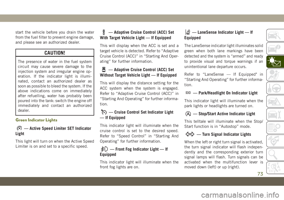
— Active Speed Limiter SET Indicator
Light
This light will turn on when the Active Speed
Limiter is on and set to a specific speed.
— Adaptive Cruise Control (ACC) Set
With Target Vehicle Light — If Equipped
This will display when the ACC is set and a
target vehicle is detected. Refer to “Adaptive
Cruise Control (ACC)” in “Starting And Oper-
ating” for further information.
— Adaptive Cruise Control (ACC) Set
Without Target Vehicle Light — If Equipped
This will display the distance setting for the
ACC system when the system is engaged.
Refer to “Adaptive Cruise Control (ACC)” in
“Starting And Operating” for further informa-
tion.
— Cruise Control Set Indicator Light
— If Equipped
This indicator light will illuminate when the
cruise control is set to the desired speed.
Refer to “Speed Control” in “Starting And
Operating” for further information.
— Front Fog Indicator Light — If
Equipped
This indicator light will illuminate when the
front fog lights are on.
— LaneSense Indicator Light — If
Equipped
The LaneSense indicator light illuminates solid
green when both lane markings have been
detected and the system is “armed” and ready
to provide visual and torque warnings if an
unintentional lane departure occurs.
Refer to “LaneSense — If Equipped" in
“Starting And Operating” for further informa-
tion.
— Park/Headlight On Indicator Light
This indicator light will illuminate when the
park lights or headlights are turned on.
— Stop/Start Active Indicator Light
This telltale will illuminate when the Stop/
Start function is in “Autostop” mode.
— Turn Signal Indicator Lights
When the left or right turn signal is activated,
the turn signal indicator will flash indepen-
dently and the corresponding exterior turn
signal lamps will flash. Turn signals can be
activated when the multifunction lever is
moved down (left) or up (right).
73
Page 81 of 344
WARNING!
acting on the vehicle, nor can it increase
the traction afforded by prevailing road
conditions. BAS cannot prevent collisions,
including those resulting from excessive
speed in turns, driving on very slippery
surfaces, or hydroplaning. The capabilities
of a BAS-equipped vehicle must never be
exploited in a reckless or dangerous man-
ner, which could jeopardize the user's
safety or the safety of others.
Hill Start Assist (HSA)
The HSA system is designed to mitigate roll
back from a complete stop while on an in-
cline. If the driver releases the brake while
stopped on an incline, HSA will continue to
hold the brake pressure for a short period. If
the driver does not apply the throttle before
this time expires, the system will release
brake pressure and the vehicle will roll down
the hill as normal.
The following conditions must be met in
order for HSA to activate:
• The feature must be enabled.• The vehicle must be stopped.
• Park brake must be off.
• Driver door must be closed.
• The vehicle must be on a sufficient grade.
• The gear selection must match vehicle up-
hill direction (i.e., vehicle facing uphill is in
forward gear; vehicle backing uphill is in
REVERSE gear).
• HSA will work in REVERSE gear and all
forward gears. The system will not activate
if the transmission is in PARK or NEU-
TRAL. For vehicles equipped with a manual
transmission, if the clutch is pressed, HSA
will remain active.
WARNING!
There may be situations where the Hill
Start Assist (HSA) will not activate and
slight rolling may occur, such as on minor
hills or with a loaded vehicle, or while
pulling a trailer. HSA is not a substitute for
active driving involvement. It is always the
driver’s responsibility to be attentive to
distance to other vehicles, people, and
objects, and most importantly brake op-
WARNING!
eration to ensure safe operation of the
vehicle under all road conditions. Your
complete attention is always required
while driving to maintain safe control of
your vehicle. Failure to follow these warn-
ings can result in a collision or serious
personal injury.
Disabling And Enabling HSA
This feature can be turned on or turned off. To
change the current setting, proceed as fol-
lows:
• If disabling HSA using your instrument
cluster display, refer to “Instrument Cluster
Display” in “Getting To Know Your Instru-
ment Panel” for further information.
• If disabling HSA using Uconnect Settings,
refer to “Uconnect Settings” in “Multime-
dia” for further information.
For vehicles not equipped with an instrument
cluster display, perform the following steps:
1. Center the steering wheel (front wheels
pointing straight forward).
79
Page 86 of 344
maneuvers; it cannot prevent wheel lift due
to other factors, such as road conditions,
leaving the roadway, or striking objects or
other vehicles.
NOTE:
ERM is disabled anytime the ESC is in “Full
Off” mode (if equipped). Refer to “Electronic
Stability Control (ESC)” in this section for a
complete explanation of the available ESC
modes.
WARNING!
Many factors, such as vehicle loading,
road conditions and driving conditions,
influence the chance that wheel lift or
rollover may occur. ERM cannot prevent
all wheel lift or roll overs, especially those
that involve leaving the roadway or striking
objects or other vehicles. The capabilities
of an ERM-equipped vehicle must never
be exploited in a reckless or dangerous
manner which could jeopardize the user's
safety or the safety of others.
Trailer Sway Control (TSC)
TSC uses sensors in the vehicle to recognize
an excessively swaying trailer and will take
the appropriate actions to attempt to stop the
sway. TSC will become active automatically
once an excessively swaying trailer is recog-
nized.
NOTE:
TSC cannot stop all trailers from swaying.
Always use caution when towing a trailer and
follow the trailer tongue weight recommenda-
tions. Refer to “Trailer Towing” in “Starting
And Operating” for further information.
When TSC is functioning, the “ESC
Activation/Malfunction Indicator Light” will
flash, the engine power may be reduced and
you may feel the brakes being applied to
individual wheels to attempt to stop the
trailer from swaying. TSC is disabled when
the ESC system is in the “Partial Off” or “Full
Off” modes.WARNING!
If TSC activates while driving, slow the
vehicle down, stop at the nearest safe
location, and adjust the trailer load to
eliminate trailer sway.
Ready Alert Braking (RAB)
Ready Alert Braking may reduce the time
required to reach full braking during emer-
gency braking situations. It anticipates when
an emergency braking situation may occur by
monitoring how fast the throttle is released by
the driver. The EBC will prepare the brake
system for a panic stop.
Rain Brake Support (RBS)
Rain Brake Support may improve braking
performance in wet conditions. It will periodi-
cally apply a small amount of brake pressure
to remove any water buildup on the front
brake rotors. It functions when the wind-
shield wipers are in LO or HI speed. When
Rain Brake Support is active, there is no
notification to the driver and no driver inter-
action is required.
SAFETY
84
Page 87 of 344
Dynamic Steering Torque (DST)
Dynamic Steering Torque is a feature of the
ESC and Electric Power Steering (EPS) mod-
ules that provides torque at the steering
wheel for certain driving conditions in which
the ESC module is detecting vehicle instabil-
ity. The torque that the steering wheel re-
ceives is only meant to help the driver realize
optimal steering behavior in order to reach/
maintain vehicle stability. The only notifica-
tion the driver receives that the feature is
active is the torque applied to the steering
wheel.
NOTE:
The DST feature is only meant to help the
driver realize the correct course of action
through small torques on the steering wheel,
which means the effectiveness of the DST
feature is highly dependent on the driver’s
sensitivity and overall reaction to the applied
torque. It is very important to realize that this
feature will not steer the vehicle, meaning the
driver is still responsible for steering the
vehicle.
Hill Descent Control (HDC) — If Equipped
HDC is intended for low speed off road driving
while in 4WD Low Range. HDC maintains
vehicle speed while descending hills during
various driving situations. HDC controls ve-
hicle speed by actively controlling the brakes.
HDC Has Three States:
1. Off (feature is not enabled and will not
activate).
2. Enabled (feature is enabled and ready but
activation conditions are not met, or driver
is actively overriding with brake or throttle
application).
3. Active (feature is enabled and actively
controlling vehicle speed).
Enabling HDC
HDC is enabled by pushing the HDC switch,
but the following conditions must also be met
to enable HDC:
• Driveline is in 4WD Low Range.
• Vehicle speed is below 5 mph (8 km/h).
• Parking brake is released.
• Driver door is closed.Activating HDC
Once HDC is enabled it will activate auto-
matically if driven down a grade of sufficient
magnitude. The set speed for HDC is select-
able by the driver, and can be adjusted by
using the gear shift +/-. The following sum-
marizes the HDC set speeds:
HDC Target Set Speeds
• P = No set speed. HDC may be enabled but
will not activate.
• R = 0.6 mph (1 km/h)
• N = 1.2 mph (2 km/h)
• D = 0.6 mph (1 km/h)
• 1st = 0.6 mph (1 km/h)
• 2nd = 1.2 mph (2 km/h)
• 3rd = 1.8 mph (3 km/h)
• 4th = 2.5 mph (4 km/h)
• 5th = 3.1 mph (5 km/h)
• 6th = 3.7 mph (6 km/h)
• 7th = 4.3 mph (7 km/h)
• 8th = 5.0 mph (8 km/h)
• 9th = 5.6 mph (9 km/h) – If Equipped
85
Page 88 of 344
NOTE:
During HDC the +/- shifter input is used for
HDC target speed selection, but will not af-
fect the gear chosen by the transmission.
When actively controlling HDC the transmis-
sion will shift appropriately for the driver-
selected set speed and corresponding driving
conditions.
Driver Override
The driver may override HDC activation with
throttle or brake application at anytime.
Deactivating HDC
HDC will be deactivated but remain available
if any of the following conditions occur:
• Driver overrides HDC set speed with throttle
or brake application.
• Vehicle speed exceeds 20 mph (32 km/h)
but remains below 40 mph (64 km/h).
• Vehicle is on a downhill grade of insuffi-
cient magnitude, is on level ground, or is on
an uphill grade.
• Vehicle is shifted to park.Disabling HDC
HDC will be deactivated and disabled if any
of the following conditions occur:
• The driver pushes the HDC switch.
• The driveline is shifted out of 4WD Low
Range.
• The parking brake is applied.
• Driver door opens.
• The vehicle is driven greater than 20 mph
(32 km/h) for greater than 70 seconds.
• The vehicle is driven greater than 40 mph
(64 km/h) (HDC exits immediately).
• HDC detects excessive brake temperature.
Feedback To The Driver
The instrument cluster has an HDC icon and
the HDC switch has an LED icon, which
offers feedback to the driver about the state
HDC is in.
• The cluster icon and switch lamp will illu-
minate and remain on solid when HDC is
enabled or activated. This is the normal
operating condition for HDC.• The cluster icon and switch lamp will flash
for several seconds then extinguish when
the driver pushes the HDC switch but en-
able conditions are not met.
• The cluster icon and switch lamp will flash
for several seconds then extinguish when
HDC disables due to excess speed.
• The cluster icon and switch lamp will flash
when HDC deactivates due to overheated
brakes. The flashing will stop and HDC will
activate again once the brakes have cooled
sufficiently.
WARNING!
HDC is only intended to assist the driver in
controlling vehicle speed when descend-
ing hills. The driver must remain attentive
to the driving conditions and is respon-
sible for maintaining a safe vehicle speed.
Selec Speed Control (SSC) — If Equipped
SSC is intended for off road driving in 4WD
Low Range only. SSC maintains vehicle
speed by actively controlling engine torque
and brakes.
SAFETY
86
Page 89 of 344
SSC has three states:
1. Off (feature is not enabled and will not
activate).
2. Enabled (feature is enabled and ready but
activation conditions are not met, or driver
is actively overriding with brake or throttle
application).
3. Active (feature is enabled and actively
controlling vehicle speed).
Enabling SSC
SSC is enabled by pushing the SSC switch,
but the following conditions must also be met
to enable SSC:
• Driveline is in 4WD Low Range.
• Vehicle speed is below 5 mph (8 km/h).
• Parking brake is released.
• Driver door is closed.
• Driver is not applying throttle.
Activating SSC
Once SSC is enabled it will activate automati-
cally once the following conditions are met:
• Driver releases throttle.• Driver releases brake.
•
Transmission is in any selection other than P.
• Vehicle speed is below 20 mph (32 km/h).
The set speed for SSC is selectable by the
driver, and can be adjusted by using the gear
shift +/-. Additionally, the SSC set speed may
be reduced when climbing a grade and the
level of set speed reduction depends on the
magnitude of grade. The following summa-
rizes the SSC set speeds:
SSC Target Set Speeds
• 1st = .6 mph (1 km/h)
• 2nd = 1.2 mph (2 km/h)
• 3rd = 1.8 mph (3 km/h)
• 4th = 2.5 mph (4 km/h)
• 5th = 3.1 mph (5 km/h)
• 6th = 3.7 mph (6 km/h)
• 7th = 4.3 mph (7 km/h)
• 8th = 5 mph (8 km/h)
• 9th = 5.6 mph (9 km/h) – If Equipped
• REVERSE = .6 mph (1 km/h)
• NEUTRAL = 1.2 mph (2 km/h)• PARK = SSC remains enabled but not
active
NOTE:
• During SSC the +/- shifter input is used for
SSC target speed selection but will not
affect the gear chosen by the transmission.
While actively controlling SSC the trans-
mission will shift appropriately for the
driver-selected set speed and correspond-
ing driving conditions.
• SSC performance is influenced by the Ter-
rain Select mode. This difference may be
notable to the driver and may be perceived
as a varying level of aggressiveness.
Driver Override:
The driver may override SSC activation with
throttle or brake application at any time.
Deactivating SSC
SSC will be deactivated but remain available
if any of the following conditions occur:
• Driver overrides SSC set speed with throttle
or brake application.
• Vehicle speed exceeds 20 mph (32 km/h)
but remains below 40 mph (64 km/h).
87
Page 90 of 344
• Vehicle is shifted to PARK.
Disabling SSC
SSC will deactivate and be disabled if any of
the following conditions occur:
• The driver pushes the SSC switch.
• The driveline is shifted out of 4WD Low
Range.
• The parking brake is applied.
• Driver door opens.
• The vehicle is driven greater than 20 mph
(32 km/h) for greater than 70 seconds.
• The vehicle is driven greater than 40 mph
(64 km/h) (SSC exits immediately).
Feedback To The Driver:
The instrument cluster has an SSC icon and
the SSC switch has an LED which offer feed-
back to the driver about the state SSC is in.
• The cluster icon and switch lamp will illu-
minate and remain on solid when SSC is
enabled or activated. This is the normal
operating condition for SSC.• The cluster icon and switch lamp will flash
for several seconds then extinguish when
the driver pushes the SSC switch but en-
able conditions are not met.
• The cluster icon and switch lamp will flash
for several seconds then extinguish when
SSC disables due to excess speed.
• The cluster icon and switch lamp will flash
then extinguish when SSC deactivates due
to overheated brakes.
WARNING!
SSC is only intended to assist the driver in
controlling vehicle speed when driving in
off road conditions. The driver must re-
main attentive to the driving conditions
and is responsible for maintaining a safe
vehicle speed.
AUXILIARY DRIVING
SYSTEMS
Blind Spot Monitoring (BSM) — If
Equipped
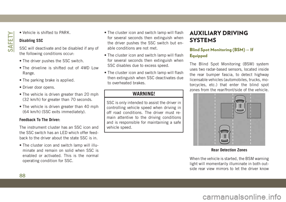
The Blind Spot Monitoring (BSM) system
uses two radar-based sensors, located inside
the rear bumper fascia, to detect highway
licensable vehicles (automobiles, trucks, mo-
torcycles, etc.) that enter the blind spot
zones from the rear/front/side of the vehicle.
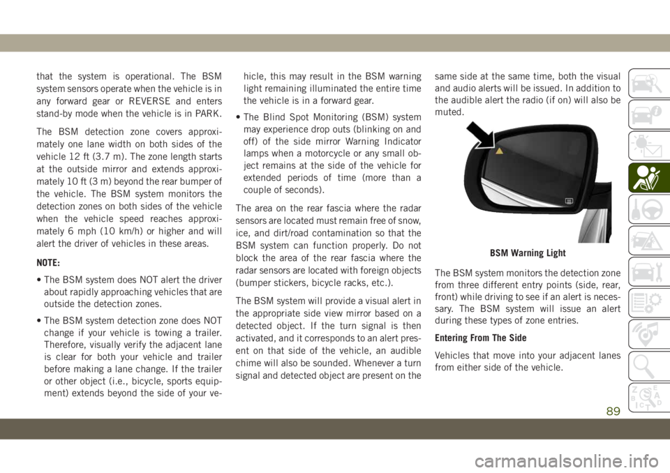
When the vehicle is started, the BSM warning
light will momentarily illuminate in both out-
side rear view mirrors to let the driver know
Rear Detection Zones
SAFETY
88
Page 91 of 344
that the system is operational. The BSM
system sensors operate when the vehicle is in
any forward gear or REVERSE and enters
stand-by mode when the vehicle is in PARK.
The BSM detection zone covers approxi-
mately one lane width on both sides of the
vehicle 12 ft (3.7 m). The zone length starts
at the outside mirror and extends approxi-
mately 10 ft (3 m) beyond the rear bumper of
the vehicle. The BSM system monitors the
detection zones on both sides of the vehicle
when the vehicle speed reaches approxi-
mately 6 mph (10 km/h) or higher and will
alert the driver of vehicles in these areas.
NOTE:
• The BSM system does NOT alert the driver
about rapidly approaching vehicles that are
outside the detection zones.
• The BSM system detection zone does NOT
change if your vehicle is towing a trailer.
Therefore, visually verify the adjacent lane
is clear for both your vehicle and trailer
before making a lane change. If the trailer
or other object (i.e., bicycle, sports equip-
ment) extends beyond the side of your ve-hicle, this may result in the BSM warning
light remaining illuminated the entire time
the vehicle is in a forward gear.
• The Blind Spot Monitoring (BSM) system
may experience drop outs (blinking on and
off) of the side mirror Warning Indicator
lamps when a motorcycle or any small ob-
ject remains at the side of the vehicle for
extended periods of time (more than a
couple of seconds).
The area on the rear fascia where the radar
sensors are located must remain free of snow,
ice, and dirt/road contamination so that the
BSM system can function properly. Do not
block the area of the rear fascia where the
radar sensors are located with foreign objects
(bumper stickers, bicycle racks, etc.).
The BSM system will provide a visual alert in
the appropriate side view mirror based on a
detected object. If the turn signal is then
activated, and it corresponds to an alert pres-
ent on that side of the vehicle, an audible
chime will also be sounded. Whenever a turn
signal and detected object are present on thesame side at the same time, both the visual
and audio alerts will be issued. In addition to
the audible alert the radio (if on) will also be
muted.
The BSM system monitors the detection zone
from three different entry points (side, rear,
front) while driving to see if an alert is neces-
sary. The BSM system will issue an alert
during these types of zone entries.
Entering From The Side
Vehicles that move into your adjacent lanes
from either side of the vehicle.
BSM Warning Light
89
Page 93 of 344
WARNING!
other vehicles, obstructions, and blind
spots before backing up. Failure to do so
can result in serious injury or death.
Modes Of Operation
Three selectable modes of operation are
available in the Uconnect System. Refer to
“Uconnect Settings” in “Multimedia” in the
Owner’s Manual for further information.
Blind Spot Alert Lights Only
When operating in Blind Spot Alert mode, the
BSM system will provide a visual alert in the
appropriate side view mirror based on a de-
tected object. However, when the system is
operating in Rear Cross Path (RCP) mode, the
system will respond with both visual and
audible alerts when a detected object is pres-
ent. Whenever an audible alert is requested,
the radio is muted.
Blind Spot Alert Lights/Chime
When operating in Blind Spot Alert Lights/
Chime mode, the BSM system will provide a
visual alert in the appropriate side view mirrorbased on a detected object. If the turn signal
is then activated, and it corresponds to an
alert present on that side of the vehicle, an
audible chime will also be sounded. When-
ever a turn signal and detected object are
present on the same side at the same time,
both the visual and audible alerts will be
issued. In addition to the audible alert the
radio (if on) will also be muted.
NOTE:
Whenever an audible alert is requested by the
BSM system, the radio is also muted.
When the system is in RCP, the system shall
respond with both visual and audible alerts
when a detected object is present. Whenever
an audible alert is requested, the radio is also
muted. Turn/hazard signal status is ignored;
the RCP state always requests the chime.
Blind Spot Alert Off
When the BSM system is turned off there will
be no visual or audible alerts from either the
BSM or RCP systems.NOTE:
The BSM system will store the current oper-
ating mode when the vehicle is shut off. Each
time the vehicle is started the previously
stored mode will be recalled and used.
Forward Collision Warning (FCW) With
Mitigation — If Equipped
Forward Collision Warning (FCW) With Miti-
gation Operation
The Forward Collision Warning (FCW) system
with mitigation provides the driver with au-
dible warnings, visual warnings (within the
instrument cluster display), and may apply a
brake jerk to warn the driver when it detects a
potential frontal collision. The warnings and
limited braking are intended to provide the
driver with enough time to react, avoid or
mitigate the potential collision.
NOTE:
FCW monitors the information from the for-
ward looking sensors as well as the Electronic
Brake Controller (EBC), to calculate the prob-
ability of a forward collision. When the sys-
91