warning JEEP CHEROKEE 2019 Owner handbook (in English)
[x] Cancel search | Manufacturer: JEEP, Model Year: 2019, Model line: CHEROKEE, Model: JEEP CHEROKEE 2019Pages: 344, PDF Size: 6.35 MB
Page 26 of 344
NOTE:
Prior to folding the rear seat, it may be
necessary to position the front seat to its
mid-track position. Also, be sure that the
front seats are fully upright and positioned
forward. This will allow the rear seat to fold
down easily.
WARNING!
• It is extremely dangerous to ride in a
cargo area, inside or outside of a vehicle.
In a collision, people riding in these
areas are more likely to be seriously
injured or killed.
• Do not allow people to ride in any area of
your vehicle that is not equipped with
seats and seat belts.
• Be sure everyone in your vehicle is in a
seat and using a seat belt properly.
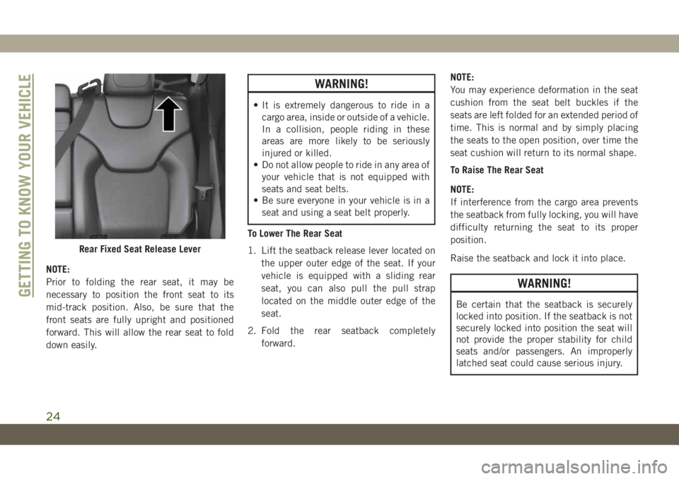
To Lower The Rear Seat
1. Lift the seatback release lever located on
the upper outer edge of the seat. If your
vehicle is equipped with a sliding rear
seat, you can also pull the pull strap
located on the middle outer edge of the
seat.
2. Fold the rear seatback completely
forward.NOTE:
You may experience deformation in the seat
cushion from the seat belt buckles if the
seats are left folded for an extended period of
time. This is normal and by simply placing
the seats to the open position, over time the
seat cushion will return to its normal shape.
To Raise The Rear Seat
NOTE:
If interference from the cargo area prevents
the seatback from fully locking, you will have
difficulty returning the seat to its proper
position.
Raise the seatback and lock it into place.
WARNING!
Be certain that the seatback is securely
locked into position. If the seatback is not
securely locked into position the seat will
not provide the proper stability for child
seats and/or passengers. An improperly
latched seat could cause serious injury.
Rear Fixed Seat Release Lever
GETTING TO KNOW YOUR VEHICLE
24
Page 28 of 344
4. Push and release the lock button on the
key fob within 10 seconds.
NOTE:
Your key fob can be unlinked to your memory
settings by pushing the set (S) button, fol-
lowed by pushing the unlock button on the
key fob within 10 seconds.
Memory Position Recall
To recall the memory settings for driver one,
push memory button (1) or the unlock button
on the key fob linked to memory position 1.
To recall the memory settings for driver two,
push memory button (2) or the unlock button
on the key fob linked to memory position 2.
A recall can be cancelled by pushing any of
the memory buttons (S, 1, or 2) during a
recall. When a recall is cancelled, the driver
seat will stop moving. A delay of one second
will occur before another recall can be se-
lected.
Easy Entry/Exit Seat — If Equipped
This feature provides automatic driver seat
positioning to enhance driver mobility when
entering and exiting the vehicle.The distance the driver seat moves depends
on where you have the driver seat positioned
when you cycle the vehicle’s ignition to the
OFF position.
Each stored memory setting will have an
associated Easy Entry and Easy Exit position.
NOTE:
The Easy Entry/Exit feature is not enabled
when the vehicle is delivered from the fac-
tory. The Easy Entry/Exit feature is enabled
(or later disabled) through the programmable
features in the Uconnect system.
Refer to “Uconnect Settings/Customer Pro-
grammable Features” in “Multimedia” in the
Owner’s Manual for further information.
Heated Seats
On some models, the front and rear seats may
be equipped with heaters located in the seat
cushions and seat backs.
WARNING!
• Persons who are unable to feel pain to
the skin because of advanced age,
WARNING!
chronic illness, diabetes, spinal cord in-
jury, medication, alcohol use, exhaus-
tion or other physical condition must
exercise care when using the seat
heater. It may cause burns even at low
temperatures, especially if used for long
periods of time.
• Do not place anything on the seat or
seatback that insulates against heat,
such as a blanket or cushion. This may
cause the seat heater to overheat. Sit-
ting in a seat that has been overheated
could cause serious burns due to the
increased surface temperature of the
seat.
Front Heated Seats
If your vehicle is equipped with front heated
seats, the control buttons are located within
the Uconnect system. You can gain access to
the control buttons through the climate
screen or the controls screen.
• Press the heated seat button
once to
turn the HI setting on.
GETTING TO KNOW YOUR VEHICLE
26
Page 29 of 344
• Press the heated seat buttona second
time to turn the LO setting on.
• Press the heated seat button
a third
time to turn the heating elements off.
If the HI-level setting is selected, the system
will automatically switch to LO-level after
approximately 60 minutes of continuous op-
eration. At that time, the display will change
from HI to LO, indicating the change. The
LO-level setting will turn off automatically
after approximately 45 minutes.
NOTE:
The engine must be running for the heated
seats to operate.
Vehicles Equipped With Remote Start
On models that are equipped with remote
start, the heated seats can be programmed to
come on during a remote start.
This feature can be programmed through the
Uconnect system. Refer to “Uconnect Set-
tings” in “Multimedia” in your Owner’s
Manual for further information.
WARNING!
• Persons who are unable to feel pain to
the skin because of advanced age,
chronic illness, diabetes, spinal cord in-
jury, medication, alcohol use, exhaus-
tion or other physical condition must
exercise care when using the seat
heater. It may cause burns even at low
temperatures, especially if used for long
periods of time.
• Do not place anything on the seat or
seatback that insulates against heat,
such as a blanket or cushion. This may
cause the seat heater to overheat. Sit-
ting in a seat that has been overheated
could cause serious burns due to the
increased surface temperature of the
seat.
Rear Heated Seats — If Equipped
On some models, the two outboard rear seats
are equipped with heated seats. The heated
seat switches for these seats are located on
the rear of the center console.There are two heated seat switches that allow
the rear passengers to operate the seats in-
dependently. Amber indicator lights in each
switch indicate the level of heat in use. Two
indicator lights will illuminate for HI, one for
LO and none for OFF.
• Push the heated seat button
once to
turn the HI setting on.
• Push the heated seat button
a second
time to turn the LO setting on.
• Push the heated seat button
a third
time to turn the heating elements off.
NOTE:
• Once a heat setting is selected, heat will be
felt within two to five minutes.
• The engine must be running for the heated
seats to operate.
When the HI-level setting is selected, the
heater will provide a boosted heat level dur-
ing the first four minutes of operation. Then,
the heat output will drop to the normal HI-
level. If the HI-level setting is selected, the
system will automatically switch to LO-level
after approximately 60 minutes of continu-
ous operation. At that time, the number of
27
Page 30 of 344
illuminated LEDs changes from two to one,
indicating the change. The LO-level setting
will turn OFF automatically after approxi-
mately 45 minutes.
Front Ventilated Seats — If Equipped
If your vehicle is equipped with ventilated
seats, the seat cushion and seat back will
have fans that draw the air from the passen-
ger compartment and move air through fine
perforations in the seat cover to help keep the
driver and front passenger cooler in higher
ambient temperatures. The fans operate at
two speeds, HI and LO.
The front ventilated seats control buttons are
located within the Uconnect system. You can
gain access to the control buttons through
the climate screen or the controls screen.
• Press the ventilated seat button
once
to choose HI.
• Press the ventilated seat button
a
second time to choose LO.
• Press the ventilated seat button
a third
time to turn the ventilated seat off.NOTE:
The engine must be running for the venti-
lated seats to operate.
Vehicles Equipped With Remote Start
On models that are equipped with remote
start, the ventilated seats can be pro-
grammed to come on during a remote start.
This feature can be programmed through the
Uconnect system. Refer to “Uconnect Set-
tings” in “Multimedia” in the Owner's
Manual.
HEAD RESTRAINTS
Head restraints are designed to reduce the
risk of injury by restricting head movement in
the event of a rear impact. Head restraints
should be adjusted so that the top of the head
restraint is located above the top of your ear.
WARNING!
• All occupants, including the driver,
should not operate a vehicle or sit in a
vehicle’s seat until the head restraints
are placed in their proper positions in
WARNING!
order to minimize the risk of neck injury
in the event of a crash.
• Head restraints should never be ad-
justed while the vehicle is in motion.
Driving a vehicle with the head restraints
improperly adjusted or removed could
cause serious injury or death in the
event of a collision.
NOTE:
Do not reverse the head restraints (making
the rear of the head restraint face forward) in
an attempt to gain additional clearance to the
back of your head.
Reactive Head Restraints — Front Seats
The front driver and passenger seats are
equipped with Reactive Head Restraints
(RHR). In the event of a rear impact, the
RHRs will automatically extend forward mini-
mizing the gap between the back of the
occupant’s head and the RHR.GETTING TO KNOW YOUR VEHICLE
28
Page 31 of 344
The RHRs will automatically return to their
normal position following a rear impact. If the
RHRs do not return to their normal position,
see your authorized dealer immediately.
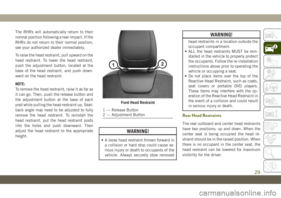
To raise the head restraint, pull upward on the
head restraint. To lower the head restraint,
push the adjustment button, located at the
base of the head restraint, and push down-
ward on the head restraint.
NOTE:
To remove the head restraint, raise it as far as
it can go. Then, push the release button and
the adjustment button at the base of each
post while pulling the head restraint up. Seat-
back angle may need to be adjusted to fully
remove the head restraint. To reinstall the
head restraint, put the head restraint posts
into the holes and push downward. Then
adjust the head restraint to the appropriate
height.
WARNING!
• A loose head restraint thrown forward in
a collision or hard stop could cause se-
rious injury or death to occupants of the
vehicle. Always securely stow removed
WARNING!
head restraints in a location outside the
occupant compartment.
• ALL the head restraints MUST be rein-
stalled in the vehicle to properly protect
the occupants. Follow the re-installation
instructions above prior to operating the
vehicle or occupying a seat.
• Do not place items over the top of the
Reactive Head Restraint, such as coats,
seat covers or portable DVD players.
These items may interfere with the op-
eration of the Reactive Head Restraint in
the event of a collision and could result
in serious injury or death.
Rear Head Restraints
The rear outboard and center head restraints
have two positions: up and down. When the
center seat is being occupied the head re-
straint should be in the raised position. When
there is no occupant in the center seat, the
head restraint can be lowered for maximum
visibility for the driver.
Front Head Restraint
1 — Release Button
2 — Adjustment Button
29
Page 32 of 344
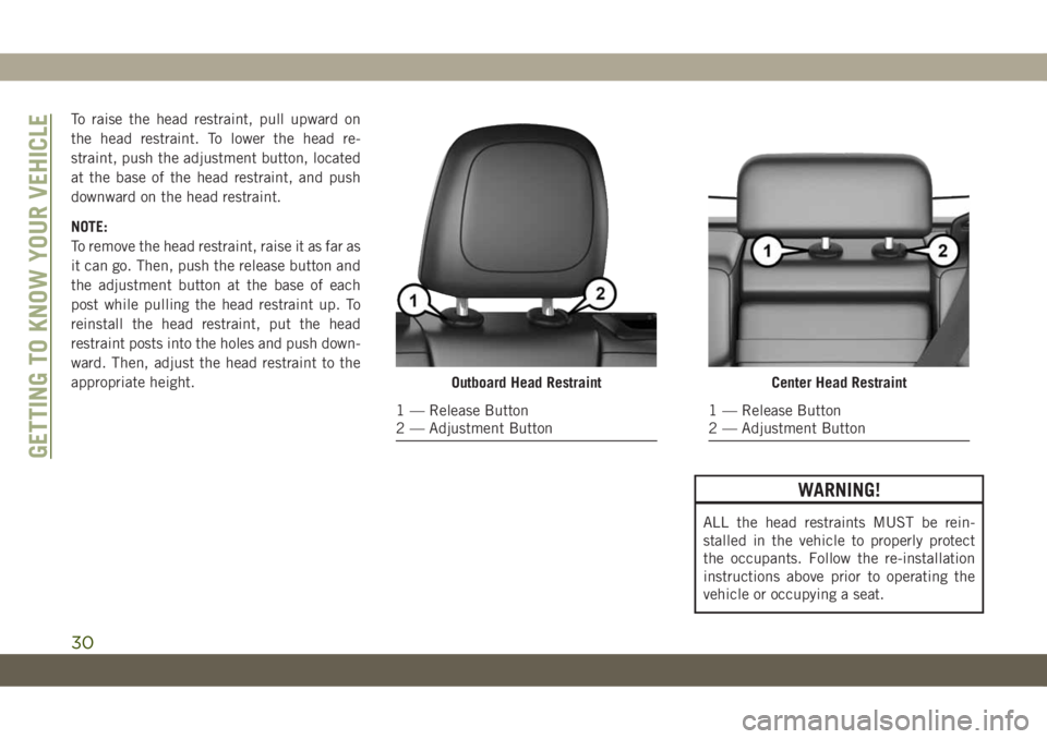
To raise the head restraint, pull upward on
the head restraint. To lower the head re-
straint, push the adjustment button, located
at the base of the head restraint, and push
downward on the head restraint.
NOTE:
To remove the head restraint, raise it as far as
it can go. Then, push the release button and
the adjustment button at the base of each
post while pulling the head restraint up. To
reinstall the head restraint, put the head
restraint posts into the holes and push down-
ward. Then, adjust the head restraint to the
appropriate height.
WARNING!
ALL the head restraints MUST be rein-
stalled in the vehicle to properly protect
the occupants. Follow the re-installation
instructions above prior to operating the
vehicle or occupying a seat.
Outboard Head Restraint
1 — Release Button
2 — Adjustment Button
Center Head Restraint
1 — Release Button
2 — Adjustment Button
GETTING TO KNOW YOUR VEHICLE
30
Page 33 of 344
STEERING WHEEL
Tilt/Telescoping Steering Column
This feature allows you to tilt the steering
column upward or downward. It also allows
you to lengthen or shorten the steering col-
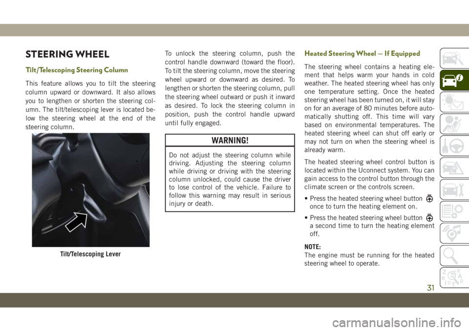
umn. The tilt/telescoping lever is located be-
low the steering wheel at the end of the
steering column.To unlock the steering column, push the
control handle downward (toward the floor).
To tilt the steering column, move the steering
wheel upward or downward as desired. To
lengthen or shorten the steering column, pull
the steering wheel outward or push it inward
as desired. To lock the steering column in
position, push the control handle upward
until fully engaged.
WARNING!
Do not adjust the steering column while
driving. Adjusting the steering column
while driving or driving with the steering
column unlocked, could cause the driver
to lose control of the vehicle. Failure to
follow this warning may result in serious
injury or death.
Heated Steering Wheel — If Equipped
The steering wheel contains a heating ele-
ment that helps warm your hands in cold
weather. The heated steering wheel has only
one temperature setting. Once the heated
steering wheel has been turned on, it will stay
on for an average of 80 minutes before auto-
matically shutting off. This time will vary
based on environmental temperatures. The
heated steering wheel can shut off early or
may not turn on when the steering wheel is
already warm.
The heated steering wheel control button is
located within the Uconnect system. You can
gain access to the control button through the
climate screen or the controls screen.
• Press the heated steering wheel button
once to turn the heating element on.
• Press the heated steering wheel button
a second time to turn the heating element
off.
NOTE:
The engine must be running for the heated
steering wheel to operate.
Tilt/Telescoping Lever
31
Page 34 of 344
Vehicles Equipped With Remote Start
On models that are equipped with remote
start, the heated steering wheel can be pro-
grammed to come on during a remote start
through the Uconnect system. Refer to
“Uconnect Settings” in “Multimedia” in the
Owner’s Manual for further information.
WARNING!
• Persons who are unable to feel pain to
the skin because of advanced age,
chronic illness, diabetes, spinal cord in-
jury, medication, alcohol use, exhaus-
tion, or other physical conditions must
exercise care when using the steering
wheel heater. It may cause burns even at
low temperatures, especially if used for
long periods.
• Do not place anything on the steering
wheel that insulates against heat, such
as a blanket or steering wheel covers of
any type and material. This may cause
the steering wheel heater to overheat.
MIRRORS
Power Folding Mirrors — If Equipped
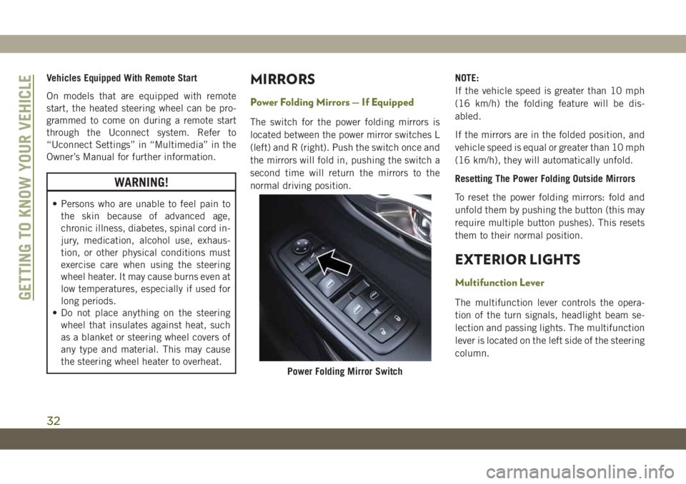
The switch for the power folding mirrors is
located between the power mirror switches L
(left) and R (right). Push the switch once and
the mirrors will fold in, pushing the switch a
second time will return the mirrors to the
normal driving position.NOTE:
If the vehicle speed is greater than 10 mph
(16 km/h) the folding feature will be dis-
abled.
If the mirrors are in the folded position, and
vehicle speed is equal or greater than 10 mph
(16 km/h), they will automatically unfold.
Resetting The Power Folding Outside Mirrors
To reset the power folding mirrors: fold and
unfold them by pushing the button (this may
require multiple button pushes). This resets
them to their normal position.
EXTERIOR LIGHTS
Multifunction Lever
The multifunction lever controls the opera-
tion of the turn signals, headlight beam se-
lection and passing lights. The multifunction
lever is located on the left side of the steering
column.
Power Folding Mirror Switch
GETTING TO KNOW YOUR VEHICLE
32
Page 39 of 344
headlights are turned on and left on for eight
minutes while the ignition is OFF, the exterior
lights will automatically turn off.
NOTE:
The battery saver mode is canceled if the
ignition is OFF and the headlamp switch is in
the park lamp position. The parking lamps
will remain on and drain the vehicle's battery.
WINDSHIELD WIPERS AND
WASHERS
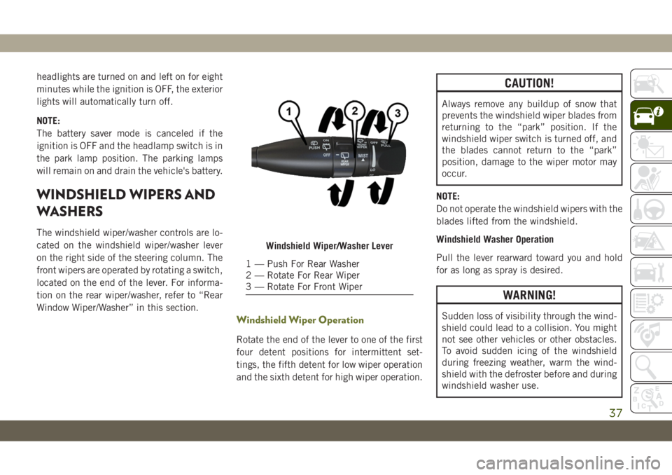
The windshield wiper/washer controls are lo-
cated on the windshield wiper/washer lever
on the right side of the steering column. The
front wipers are operated by rotating a switch,
located on the end of the lever. For informa-
tion on the rear wiper/washer, refer to “Rear
Window Wiper/Washer” in this section.
Windshield Wiper Operation
Rotate the end of the lever to one of the first
four detent positions for intermittent set-
tings, the fifth detent for low wiper operation
and the sixth detent for high wiper operation.
CAUTION!
Always remove any buildup of snow that
prevents the windshield wiper blades from
returning to the “park” position. If the
windshield wiper switch is turned off, and
the blades cannot return to the “park”
position, damage to the wiper motor may
occur.
NOTE:
Do not operate the windshield wipers with the
blades lifted from the windshield.
Windshield Washer Operation
Pull the lever rearward toward you and hold
for as long as spray is desired.
WARNING!
Sudden loss of visibility through the wind-
shield could lead to a collision. You might
not see other vehicles or other obstacles.
To avoid sudden icing of the windshield
during freezing weather, warm the wind-
shield with the defroster before and during
windshield washer use.
Windshield Wiper/Washer Lever
1 — Push For Rear Washer
2 — Rotate For Rear Wiper
3 — Rotate For Front Wiper
37
Page 52 of 344
NOTE:
For vehicles equipped with the Uconnect, the
power window switches will remain active for
up to 10 minutes after the ignition is cycled
to the OFF position. Opening either front door
will cancel this feature. The time is program-
mable. Refer to “Uconnect Settings” in
“Multimedia” in your Owner’s Manual for
further information.
WARNING!
Never leave children unattended in a ve-
hicle, and do not let children play with
power windows. Do not leave the key fob in
or near the vehicle, or in a location acces-
sible to children, and do not leave the
ignition of a vehicle equipped with Keyless
Enter-N-Go in the ACC or ON/RUN mode.
Occupants, particularly unattended chil-
dren, can become entrapped by the win-
dows while operating the power window
switches. Such entrapment may result in
serious injury or death.
Auto-Up Feature With Anti-Pinch
Protection
NOTE:
• If the window runs into any obstacle during
auto-closure, it will reverse direction and
then go back down. Remove the obstacle
and use the window switch again to close
the window.
• Any impact due to rough road conditions
may trigger the auto-reverse function unex-
pectedly during auto-closure. If this hap-
pens, pull the switch lightly and hold to
close the window manually.
WARNING!
There is no anti-pinch protection when the
window is almost closed. To avoid personal
injury be sure to clear your arms, hands,
fingers and all objects from the window
path before closing.
Window Lockout Switch
The window lockout switch on the driver's
door trim panel allows you to disable the
window controls on the rear passenger doors.
To disable the window controls, push and
release the window lockout button (the indi-
cator light on the button with turn on). To
enable the window controls, push and release
the window lockout button again (the indica-
tor light on the button will turn back off).
Wind Buffeting
Wind buffeting can be described as the per-
ception of pressure on the ears or a
helicopter-type sound in the ears. Your ve-
hicle may exhibit wind buffeting with the
windows down, or the sunroof (if equipped) in
certain open or partially open positions. This
is a normal occurrence and can be mini-
mized. If the buffeting occurs with the rear
windows open, open the front and rear win-
dows together to minimize the buffeting. If
the buffeting occurs with the sunroof open,
adjust the sunroof opening to minimize the
buffeting or open any window.
GETTING TO KNOW YOUR VEHICLE
50