buttons JEEP CHEROKEE 2019 Owner handbook (in English)
[x] Cancel search | Manufacturer: JEEP, Model Year: 2019, Model line: CHEROKEE, Model: JEEP CHEROKEE 2019Pages: 344, PDF Size: 6.35 MB
Page 22 of 344
battery is reconnected; the exterior lights will
flash, and the horn will sound. If this occurs,
disarm the vehicle security alarm.
DOORS
Keyless Enter-N-Go — Passive Entry
The Passive Entry system is an enhancement
to the vehicle’s Remote Keyless Entry system
and a feature of Keyless Enter-N-Go — Pas-
sive Entry. This feature allows you to lock and
unlock the vehicle’s door(s) and fuel door
without having to push the key fob lock or
unlock buttons.
NOTE:
• Passive Entry may be programmed ON/
OFF; refer to “Uconnect Settings” in “Mul-
timedia” in the Owner’s Manual for further
information.
• If wearing gloves on your hands, or if it has
been raining/snowing on the Passive Entry
door handle, the unlock sensitivity can be
affected, resulting in a slower response
time.• If the vehicle is unlocked by Passive Entry
and no door is opened within 60 seconds,
the vehicle will re-lock and if equipped will
arm the security alarm.
• The key fob may not be able to be detected
by the vehicle passive entry system if it is
located next to a mobile phone, laptop or
other electronic device; these devices may
block the key fob's wireless signal and
prevent the passive entry handle from
locking/unlocking the vehicle.
• Passive Entry activates illuminated ap-
proach for the time set by the customer (0,
30, 60, or 90 seconds), and flashes the
turn signal lights. Refer to “Uconnect Set-
tings” in “Multimedia in the Owner’s
Manual for further information.
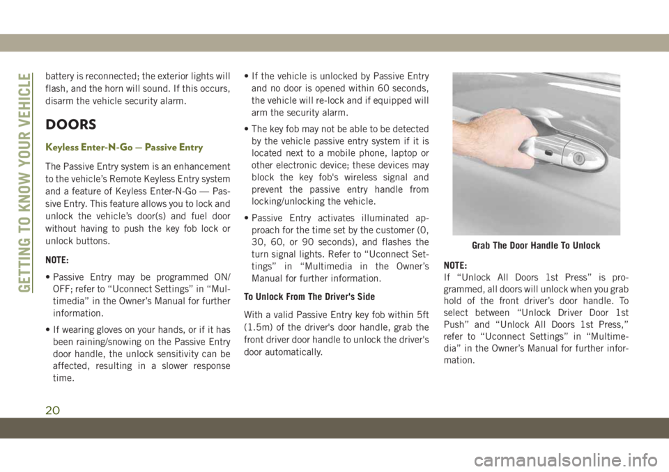
To Unlock From The Driver's Side
With a valid Passive Entry key fob within 5ft
(1.5m) of the driver's door handle, grab the
front driver door handle to unlock the driver's
door automatically.NOTE:
If “Unlock All Doors 1st Press” is pro-
grammed, all doors will unlock when you grab
hold of the front driver’s door handle. To
select between “Unlock Driver Door 1st
Push” and “Unlock All Doors 1st Press,”
refer to “Uconnect Settings” in “Multime-
dia” in the Owner’s Manual for further infor-
mation.
Grab The Door Handle To Unlock
GETTING TO KNOW YOUR VEHICLE
20
Page 27 of 344
Driver Memory Seat — If Equipped
The memory seat feature allows you to save
two different driver seating positions, driver's
outside mirror, and radio station preset set-
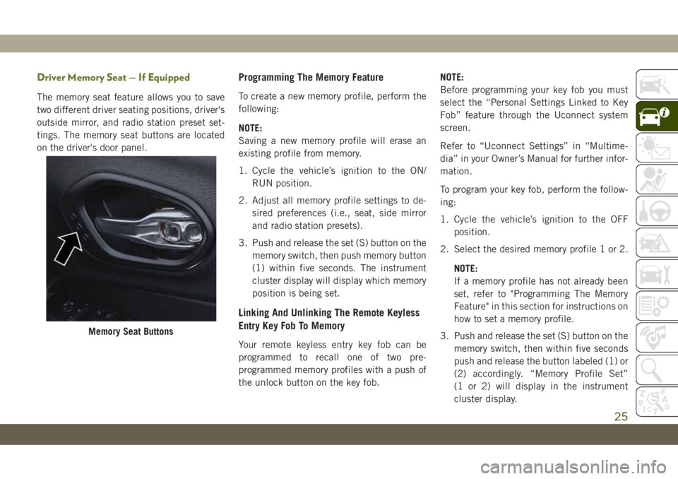
tings. The memory seat buttons are located
on the driver's door panel.
Programming The Memory Feature
To create a new memory profile, perform the
following:
NOTE:
Saving a new memory profile will erase an
existing profile from memory.
1. Cycle the vehicle’s ignition to the ON/
RUN position.
2. Adjust all memory profile settings to de-
sired preferences (i.e., seat, side mirror
and radio station presets).
3. Push and release the set (S) button on the
memory switch, then push memory button
(1) within five seconds. The instrument
cluster display will display which memory
position is being set.
Linking And Unlinking The Remote Keyless
Entry Key Fob To Memory
Your remote keyless entry key fob can be
programmed to recall one of two pre-
programmed memory profiles with a push of
the unlock button on the key fob.NOTE:
Before programming your key fob you must
select the “Personal Settings Linked to Key
Fob” feature through the Uconnect system
screen.
Refer to “Uconnect Settings” in “Multime-
dia” in your Owner’s Manual for further infor-
mation.
To program your key fob, perform the follow-
ing:
1. Cycle the vehicle’s ignition to the OFF
position.
2. Select the desired memory profile 1 or 2.
NOTE:
If a memory profile has not already been
set, refer to "Programming The Memory
Feature" in this section for instructions on
how to set a memory profile.
3. Push and release the set (S) button on the
memory switch, then within five seconds
push and release the button labeled (1) or
(2) accordingly. “Memory Profile Set”
(1 or 2) will display in the instrument
cluster display.
Memory Seat Buttons
25
Page 28 of 344
4. Push and release the lock button on the
key fob within 10 seconds.
NOTE:
Your key fob can be unlinked to your memory
settings by pushing the set (S) button, fol-
lowed by pushing the unlock button on the
key fob within 10 seconds.
Memory Position Recall
To recall the memory settings for driver one,
push memory button (1) or the unlock button
on the key fob linked to memory position 1.
To recall the memory settings for driver two,
push memory button (2) or the unlock button
on the key fob linked to memory position 2.
A recall can be cancelled by pushing any of
the memory buttons (S, 1, or 2) during a
recall. When a recall is cancelled, the driver
seat will stop moving. A delay of one second
will occur before another recall can be se-
lected.
Easy Entry/Exit Seat — If Equipped
This feature provides automatic driver seat
positioning to enhance driver mobility when
entering and exiting the vehicle.The distance the driver seat moves depends
on where you have the driver seat positioned
when you cycle the vehicle’s ignition to the
OFF position.
Each stored memory setting will have an
associated Easy Entry and Easy Exit position.
NOTE:
The Easy Entry/Exit feature is not enabled
when the vehicle is delivered from the fac-
tory. The Easy Entry/Exit feature is enabled
(or later disabled) through the programmable
features in the Uconnect system.
Refer to “Uconnect Settings/Customer Pro-
grammable Features” in “Multimedia” in the
Owner’s Manual for further information.
Heated Seats
On some models, the front and rear seats may
be equipped with heaters located in the seat
cushions and seat backs.
WARNING!
• Persons who are unable to feel pain to
the skin because of advanced age,
WARNING!
chronic illness, diabetes, spinal cord in-
jury, medication, alcohol use, exhaus-
tion or other physical condition must
exercise care when using the seat
heater. It may cause burns even at low
temperatures, especially if used for long
periods of time.
• Do not place anything on the seat or
seatback that insulates against heat,
such as a blanket or cushion. This may
cause the seat heater to overheat. Sit-
ting in a seat that has been overheated
could cause serious burns due to the
increased surface temperature of the
seat.
Front Heated Seats
If your vehicle is equipped with front heated
seats, the control buttons are located within
the Uconnect system. You can gain access to
the control buttons through the climate
screen or the controls screen.
• Press the heated seat button
once to
turn the HI setting on.
GETTING TO KNOW YOUR VEHICLE
26
Page 30 of 344
illuminated LEDs changes from two to one,
indicating the change. The LO-level setting
will turn OFF automatically after approxi-
mately 45 minutes.
Front Ventilated Seats — If Equipped
If your vehicle is equipped with ventilated
seats, the seat cushion and seat back will
have fans that draw the air from the passen-
ger compartment and move air through fine
perforations in the seat cover to help keep the
driver and front passenger cooler in higher
ambient temperatures. The fans operate at
two speeds, HI and LO.
The front ventilated seats control buttons are
located within the Uconnect system. You can
gain access to the control buttons through
the climate screen or the controls screen.
• Press the ventilated seat button
once
to choose HI.
• Press the ventilated seat button
a
second time to choose LO.
• Press the ventilated seat button
a third
time to turn the ventilated seat off.NOTE:
The engine must be running for the venti-
lated seats to operate.
Vehicles Equipped With Remote Start
On models that are equipped with remote
start, the ventilated seats can be pro-
grammed to come on during a remote start.
This feature can be programmed through the
Uconnect system. Refer to “Uconnect Set-
tings” in “Multimedia” in the Owner's
Manual.
HEAD RESTRAINTS
Head restraints are designed to reduce the
risk of injury by restricting head movement in
the event of a rear impact. Head restraints
should be adjusted so that the top of the head
restraint is located above the top of your ear.
WARNING!
• All occupants, including the driver,
should not operate a vehicle or sit in a
vehicle’s seat until the head restraints
are placed in their proper positions in
WARNING!
order to minimize the risk of neck injury
in the event of a crash.
• Head restraints should never be ad-
justed while the vehicle is in motion.
Driving a vehicle with the head restraints
improperly adjusted or removed could
cause serious injury or death in the
event of a collision.
NOTE:
Do not reverse the head restraints (making
the rear of the head restraint face forward) in
an attempt to gain additional clearance to the
back of your head.
Reactive Head Restraints — Front Seats
The front driver and passenger seats are
equipped with Reactive Head Restraints
(RHR). In the event of a rear impact, the
RHRs will automatically extend forward mini-
mizing the gap between the back of the
occupant’s head and the RHR.GETTING TO KNOW YOUR VEHICLE
28
Page 47 of 344
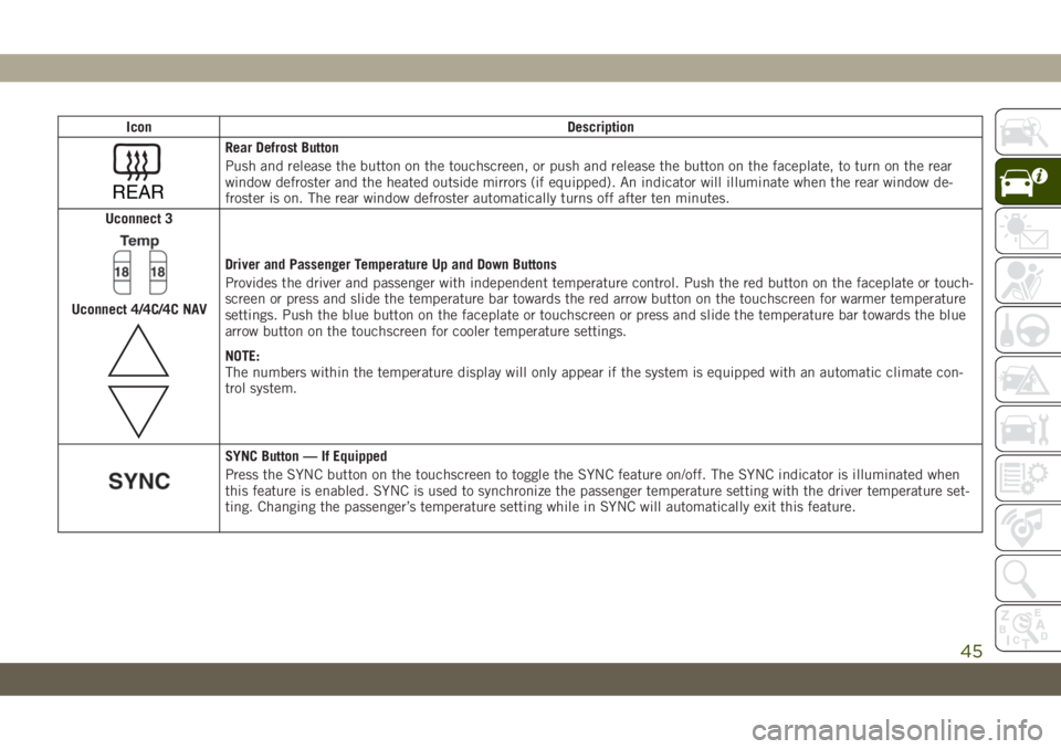
Icon Description
REAR
Rear Defrost Button
Push and release the button on the touchscreen, or push and release the button on the faceplate, to turn on the rear
window defroster and the heated outside mirrors (if equipped). An indicator will illuminate when the rear window de-
froster is on. The rear window defroster automatically turns off after ten minutes.
Uconnect 3
Uconnect 4/4C/4C NAV
Driver and Passenger Temperature Up and Down Buttons
Provides the driver and passenger with independent temperature control. Push the red button on the faceplate or touch-
screen or press and slide the temperature bar towards the red arrow button on the touchscreen for warmer temperature
settings. Push the blue button on the faceplate or touchscreen or press and slide the temperature bar towards the blue
arrow button on the touchscreen for cooler temperature settings.
NOTE:
The numbers within the temperature display will only appear if the system is equipped with an automatic climate con-
trol system.
SYNC Button — If Equipped
Press the SYNC button on the touchscreen to toggle the SYNC feature on/off. The SYNC indicator is illuminated when
this feature is enabled. SYNC is used to synchronize the passenger temperature setting with the driver temperature set-
ting. Changing the passenger’s temperature setting while in SYNC will automatically exit this feature.
45
Page 48 of 344
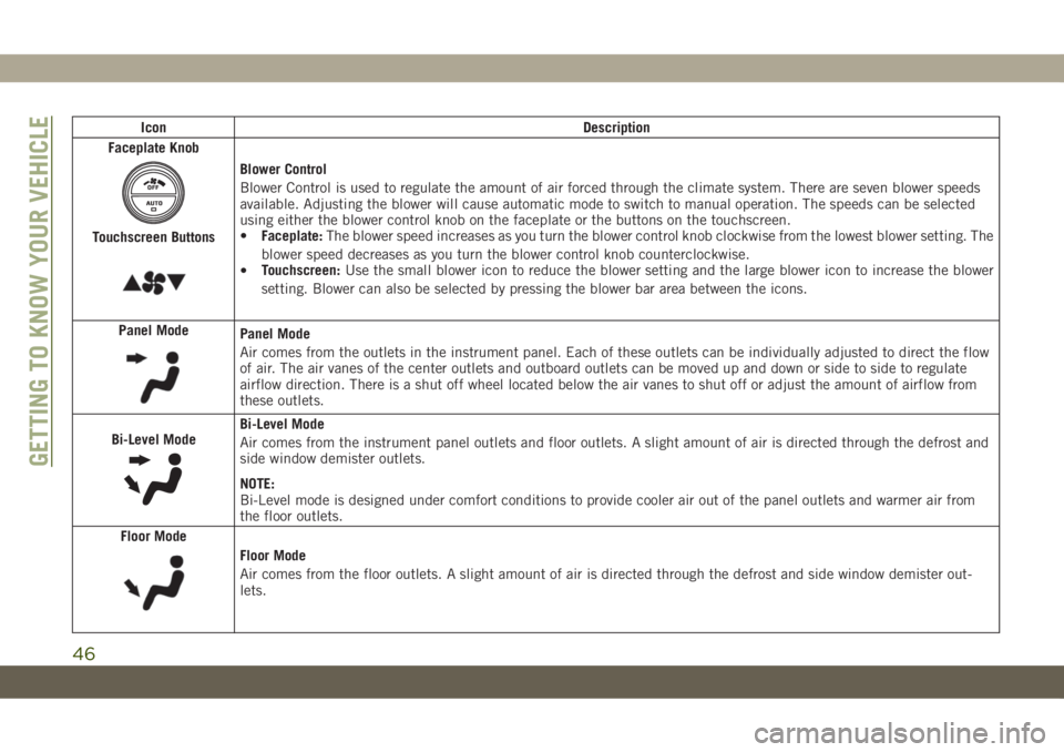
Icon Description
Faceplate Knob
Touchscreen Buttons
Blower Control
Blower Control is used to regulate the amount of air forced through the climate system. There are seven blower speeds
available. Adjusting the blower will cause automatic mode to switch to manual operation. The speeds can be selected
using either the blower control knob on the faceplate or the buttons on the touchscreen.
•Faceplate:The blower speed increases as you turn the blower control knob clockwise from the lowest blower setting. The
blower speed decreases as you turn the blower control knob counterclockwise.
•Touchscreen:Use the small blower icon to reduce the blower setting and the large blower icon to increase the blower
setting. Blower can also be selected by pressing the blower bar area between the icons.
Panel Mode
Panel Mode
Air comes from the outlets in the instrument panel. Each of these outlets can be individually adjusted to direct the flow
of air. The air vanes of the center outlets and outboard outlets can be moved up and down or side to side to regulate
airflow direction. There is a shut off wheel located below the air vanes to shut off or adjust the amount of airflow from
these outlets.
Bi-Level Mode
Bi-Level Mode
Air comes from the instrument panel outlets and floor outlets. A slight amount of air is directed through the defrost and
side window demister outlets.
NOTE:
Bi-Level mode is designed under comfort conditions to provide cooler air out of the panel outlets and warmer air from
the floor outlets.
Floor Mode
Floor Mode
Air comes from the floor outlets. A slight amount of air is directed through the defrost and side window demister out-
lets.
GETTING TO KNOW YOUR VEHICLE
46
Page 50 of 344
(button on the touchscreen greyed out) if
conditions exist that could create fogging on
the inside of the windshield.
Automatic Temperature Control (ATC) —
If Equipped
Automatic Operation
1. Push the AUTO button on the faceplate,
or the AUTO button on the touchscreen on
the Automatic Temperature Control (ATC)
Panel.
2. Next, adjust the temperature you would
like the system to maintain by adjusting
the driver and passenger temperature
control buttons. Once the desired tem-
perature is displayed, the system will
achieve and automatically maintain that
comfort level.
3. When the system is set up for your comfort
level, it is not necessary to change the
settings. You will experience the greatest
efficiency by simply allowing the system
to function automatically.NOTE:
• It is not necessary to move the temperature
settings for cold or hot vehicles. The system
automatically adjusts the temperature,
mode, and blower speed to provide comfort
as quickly as possible.
• The temperature can be displayed in U.S.
or Metric units by selecting the US/Metric
customer-programmable feature. Refer to
the “Uconnect Settings” in “Multimedia”
in your Owner’s Manual for further
information.
To provide you with maximum comfort in the
Automatic mode during cold start-ups, the
blower fan will remain on low until the engine
warms up. The blower will increase in speed
and transition into Auto mode.
Manual Operation Override
This system offers a full complement of
manual override features. The AUTO symbol
in the front ATC display will be turned off
when the system is being used in the manual
mode.
Operating Tips
Summer Operation
The engine cooling system must be protected
with a high-quality antifreeze coolant to pro-
vide proper corrosion protection and to pro-
tect against engine overheating. OAT coolant
(conforming to MS.90032) is recommended.
Winter Operation
To ensure the best possible heater and de-
froster performance, make sure the engine
cooling system is functioning properly and
the proper amount, type, and concentration
of coolant is used. Use of the Air Recircula-
tion mode during Winter months is not rec-
ommended, because it may cause window
fogging.
Vacation/Storage
Before you store your vehicle, or keep it out of
service (i.e., vacation) for two weeks or more,
run the air conditioning system at idle for
about five minutes, in fresh air with the
blower setting on high. This will ensure ad-
GETTING TO KNOW YOUR VEHICLE
48
Page 64 of 344
INSTRUMENT CLUSTER
DISPLAY
Your vehicle may be equipped with an instru-
ment cluster display, which offers useful in-
formation to the driver. With the ignition in
the STOP/OFF mode, opening/closing of a
door will activate the display for viewing, and
display the total miles, or kilometers, in the
odometer. Your instrument cluster display is
designed to display important information
about your vehicle’s systems and features.
Using a driver interactive display located on
the instrument panel, your instrument clus-
ter display can show you how systems are
working and give you warnings when they
aren’t. The steering wheel mounted controls
allow you to scroll through and enter the main
menus and submenus. You can access the
specific information you want and make se-
lections and adjustments.
Instrument Cluster Display Location And
Controls
The instrument cluster display features a
driver-interactive display that is located in
the instrument cluster.
The instrument cluster display menu items
consist of the following:
• Speedometer
• Vehicle Info
• Driver Assist — If Equipped
• Fuel Economy
• Trip Info
• Stop/Start
• Audio
• Messages
• Screen Setup
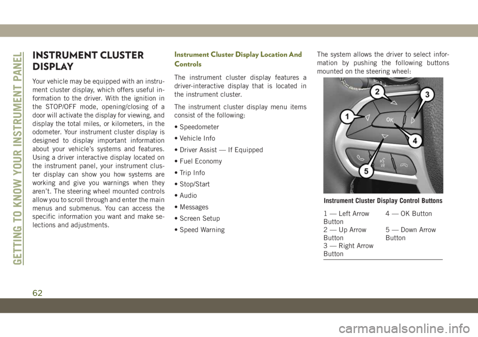
• Speed WarningThe system allows the driver to select infor-
mation by pushing the following buttons
mounted on the steering wheel:
Instrument Cluster Display Control Buttons
1 — Left Arrow
Button4 — OK Button
2 — Up Arrow
Button5 — Down Arrow
Button
3 — Right Arrow
Button
GETTING TO KNOW YOUR INSTRUMENT PANEL
62
Page 156 of 344
7. After the shift is completed and the NEU-
TRAL (N) light stays on, release the NEU-
TRAL (N) button.
8. Start the engine.
9. Release the parking brake.
10. Shift the transmission into REVERSE.
11. Release the brake pedal (and clutch
pedal on manual transmissions) for five
seconds and ensure that there is no
vehicle movement.
12. Shift the transmission to NEUTRAL.
13. Apply the parking brake.
14. Shift the automatic transmission into
PARK, or place manual transmission in
gear (NOT in Neutral). Turn the engine
OFF, and remove the key fob.
Repeat steps 1-7 to shift out of NEUTRAL.
Refer to "Recreational Towing" in "Starting
and Operating" for further instructions.Rear Electronic Locker (E-Locker) System
— If Equipped
The Rear E-Locker System features a me-
chanical locking rear differential to provide
better traction in the 4WD LOW position. The
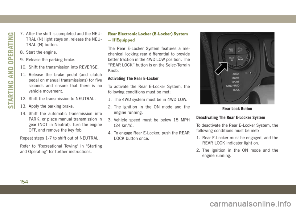
“REAR LOCK” button is on the Selec-Terrain
Knob.
Activating The Rear E-Locker
To activate the Rear E-Locker System, the
following conditions must be met:
1. The 4WD system must be in 4WD LOW.
2. The ignition in the ON mode and the
engine running.
3. Vehicle speed must be below 15 MPH
(24 km/h).
4. To engage Rear E-Locker, push the REAR
LOCK button once.Deactivating The Rear E-Locker System
To deactivate the Rear E-Locker System, the
following conditions must be met:
1. Rear E-Locker must be engaged, and the
REAR LOCK indicator light on.
2. The ignition in the ON mode and the
engine running.
Rear Lock ButtonSTARTING AND OPERATING
154
Page 163 of 344
3. At the next vehicle stop (after turning off
the STOP/START system) the engine will
not be stopped.
4. If the STOP/START system is manually
turned off, the engine can only be started
and stopped by cycling the ignition
switch.
5. The STOP/START system will reset itself
back to an ON condition every time the
key is turned off and back on.
To Manually Turn On The Stop/Start
System
Push the STOP/START Off switch (located on
the switch bank). The light on the switch will
turn off.
SPEED CONTROL
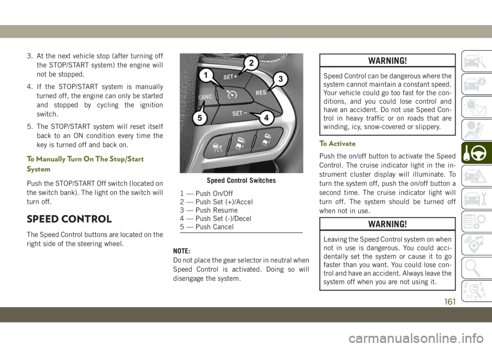
The Speed Control buttons are located on the
right side of the steering wheel.
NOTE:
Do not place the gear selector in neutral when
Speed Control is activated. Doing so will
disengage the system.
WARNING!
Speed Control can be dangerous where the
system cannot maintain a constant speed.
Your vehicle could go too fast for the con-
ditions, and you could lose control and
have an accident. Do not use Speed Con-
trol in heavy traffic or on roads that are
winding, icy, snow-covered or slippery.
To Activate
Push the on/off button to activate the Speed
Control. The cruise indicator light in the in-
strument cluster display will illuminate. To
turn the system off, push the on/off button a
second time. The cruise indicator light will
turn off. The system should be turned off
when not in use.
WARNING!
Leaving the Speed Control system on when
not in use is dangerous. You could acci-
dentally set the system or cause it to go
faster than you want. You could lose con-
trol and have an accident. Always leave the
system off when you are not using it.
Speed Control Switches
1 — Push On/Off
2 — Push Set (+)/Accel
3 — Push Resume
4 — Push Set (-)/Decel
5 — Push Cancel
161