stop start JEEP CHEROKEE 2019 Owner handbook (in English)
[x] Cancel search | Manufacturer: JEEP, Model Year: 2019, Model line: CHEROKEE, Model: JEEP CHEROKEE 2019Pages: 344, PDF Size: 6.35 MB
Page 9 of 344
INTERNAL EQUIPMENT................. 58Power Outlets................... 58
Power Inverter — If Equipped......... 60
ROOF LUGGAGE RACK — IF EQUIPPED......... 60
GETTING TO KNOW YOUR INSTRU-
MENT PANEL
INSTRUMENT CLUSTER DISPLAY............ 62Instrument Cluster Display Location And
Controls....................... 62
Instrument Cluster Display Selectable Items . 63
Diesel Displays................... 63
Diesel Particulate Filter (DPF) Messages . . . 63
WARNING LIGHTS AND MESSAGES.......... 64Red Warning Lights................ 64
Yellow Warning Lights............... 68
Yellow Indicator Lights.............. 72
Green Indicator Lights.............. 73
White Indicator Lights.............. 74
Blue Indicator Lights............... 75
ONBOARD DIAGNOSTIC SYSTEM — OBD II...... 75Onboard Diagnostic System (OBD II)
Cybersecurity.................... 76
SAFETY
SAFETY FEATURES................... 77Anti-Lock Brake System (ABS)......... 77
Electronic Brake Control System........ 78
AUXILIARY DRIVING SYSTEMS............. 88Blind Spot Monitoring (BSM) — If Equipped . 88
Forward Collision Warning (FCW) With Mitigation
— If Equipped................... 91
Tire Pressure Monitor System (TPMS)..... 94
OCCUPANT RESTRAINT SYSTEMS........... 98Occupant Restraint Systems Features..... 98
Important Safety Precautions.......... 98
Seat Belt Systems................ 100
Supplemental Restraint Systems (SRS) . . . 109
Child Restraints — Carrying Children
Safely....................... 119
Transporting Pets................ 135
SAFETY TIPS..................... 136Transporting Passengers............ 136
Exhaust Gas................... 136
Safety Checks You Should Make Inside The
Vehicle...................... 136
Periodic Safety Checks You Should Make
Outside The Vehicle............... 138
STARTING AND OPERATING
STARTING THE ENGINE................ 139Normal Starting — Gasoline Engine..... 139
Extreme Cold Weather
(Below –22°F Or −30°C)............ 140
Normal Starting — Diesel Engine....... 140
ENGINE BREAK-IN RECOMMENDATIONS....... 141
PARKING BRAKE.................... 142
Electric Park Brake (EPB)........... 142
MANUAL TRANSMISSION — IF EQUIPPED...... 144Shifting...................... 144
Downshifting................... 145
AUTOMATIC TRANSMISSION — IF EQUIPPED.... 146Key Ignition Park Interlock........... 147
Brake/Transmission Shift Interlock System . 148
Nine-Speed Automatic Transmission..... 148
Gear Ranges.................... 149
FOUR-WHEEL DRIVE OPERATION........... 1501-Speed Four-Wheel Drive (4X4) — If
Equipped..................... 150
2-Speed Four-Wheel Drive (4x4) — If
Equipped..................... 151
Shift Positions.................. 152
Shifting Procedures............... 152
Rear Electronic Locker (E-Locker) System — If
Equipped..................... 154
SELEC-TERRAIN.................... 155Description.................... 155
STOP/START SYSTEM................. 156Automatic Mode................. 156
Possible Reasons The Engine Does Not
Autostop...................... 157
To Start The Engine While In Autostop
Mode........................ 157
To Manually Turn Off The Stop/Start
System...................... 158
To Manually Turn On The Stop/Start System . 158
STOP/START SYSTEM — DIESEL MODELS ONLY . . 158Automatic Mode................. 159
Possible Reasons The Engine Does Not
Autostop...................... 159
To Start The Engine While In Autostop
Mode........................ 160
To Manually Turn Off The Stop/Start
System....................... 160
To Manually Turn On The Stop/Start System . 161
SPEED CONTROL.................... 161To Activate.................... 161
To Set A Desired Speed............. 162
To Resume Speed................ 162
To Deactivate................... 162
7
Page 15 of 344
KEYS
Key Fob
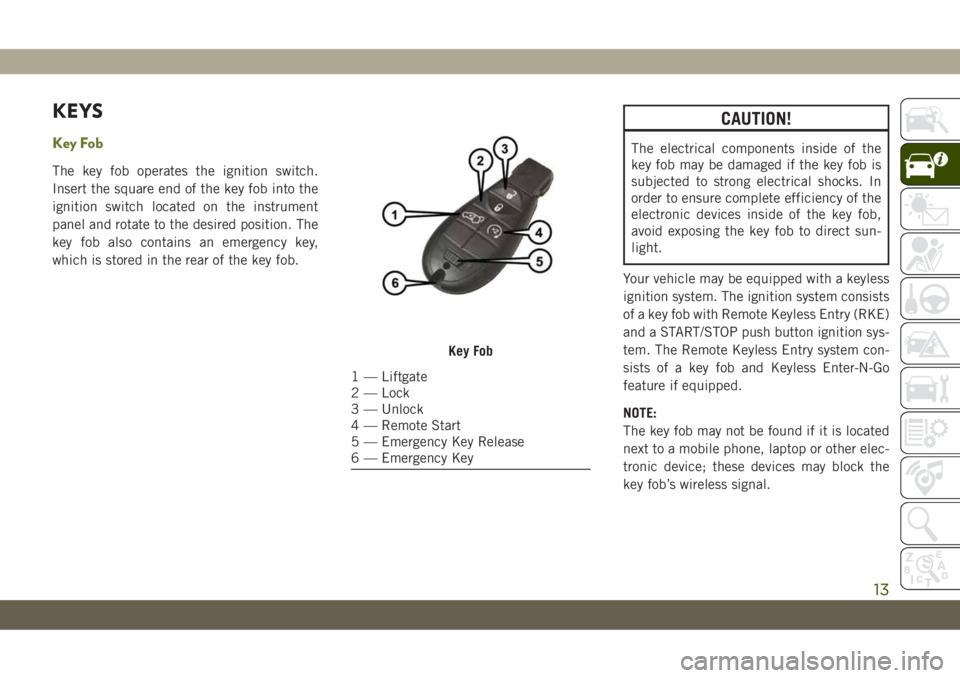
The key fob operates the ignition switch.
Insert the square end of the key fob into the
ignition switch located on the instrument
panel and rotate to the desired position. The
key fob also contains an emergency key,
which is stored in the rear of the key fob.
CAUTION!
The electrical components inside of the
key fob may be damaged if the key fob is
subjected to strong electrical shocks. In
order to ensure complete efficiency of the
electronic devices inside of the key fob,
avoid exposing the key fob to direct sun-
light.
Your vehicle may be equipped with a keyless
ignition system. The ignition system consists
of a key fob with Remote Keyless Entry (RKE)
and a START/STOP push button ignition sys-
tem. The Remote Keyless Entry system con-
sists of a key fob and Keyless Enter-N-Go
feature if equipped.
NOTE:
The key fob may not be found if it is located
next to a mobile phone, laptop or other elec-
tronic device; these devices may block the
key fob’s wireless signal.
Key Fob
1 — Liftgate
2 — Lock
3 — Unlock
4 — Remote Start
5 — Emergency Key Release
6 — Emergency Key
13
Page 16 of 344
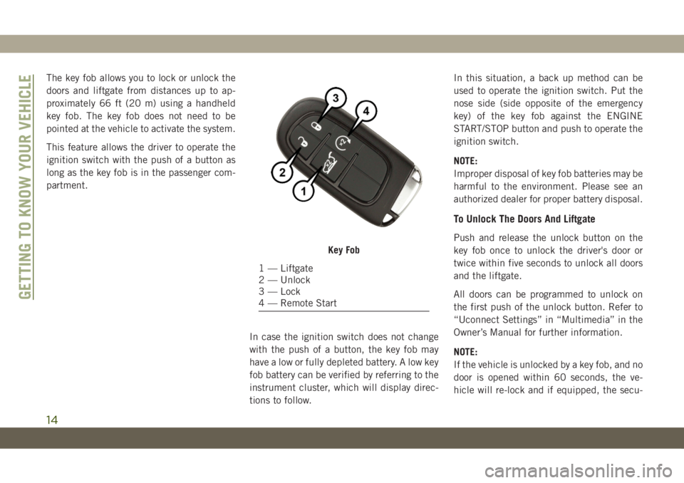
The key fob allows you to lock or unlock the
doors and liftgate from distances up to ap-
proximately 66 ft (20 m) using a handheld
key fob. The key fob does not need to be
pointed at the vehicle to activate the system.
This feature allows the driver to operate the
ignition switch with the push of a button as
long as the key fob is in the passenger com-
partment.
In case the ignition switch does not change
with the push of a button, the key fob may
have a low or fully depleted battery. A low key
fob battery can be verified by referring to the
instrument cluster, which will display direc-
tions to follow.In this situation, a back up method can be
used to operate the ignition switch. Put the
nose side (side opposite of the emergency
key) of the key fob against the ENGINE
START/STOP button and push to operate the
ignition switch.
NOTE:
Improper disposal of key fob batteries may be
harmful to the environment. Please see an
authorized dealer for proper battery disposal.
To Unlock The Doors And Liftgate
Push and release the unlock button on the
key fob once to unlock the driver's door or
twice within five seconds to unlock all doors
and the liftgate.
All doors can be programmed to unlock on
the first push of the unlock button. Refer to
“Uconnect Settings” in “Multimedia” in the
Owner’s Manual for further information.
NOTE:
If the vehicle is unlocked by a key fob, and no
door is opened within 60 seconds, the ve-
hicle will re-lock and if equipped, the secu-
Key Fob
1 — Liftgate
2 — Unlock
3 — Lock
4 — Remote Start
GETTING TO KNOW YOUR VEHICLE
14
Page 18 of 344
WARNING!
Never remove the mechanical key while
the vehicle is moving, as the steering
wheel will automatically lock as soon as
WARNING!
the key is turned. This also applies to
vehicles that are being towed.
Keyless Enter-N-Go (Ignition) — If
Equipped
This feature allows the driver to operate the
ignition switch with the push of a button as
long as the key fob is in the passenger com-
partment.
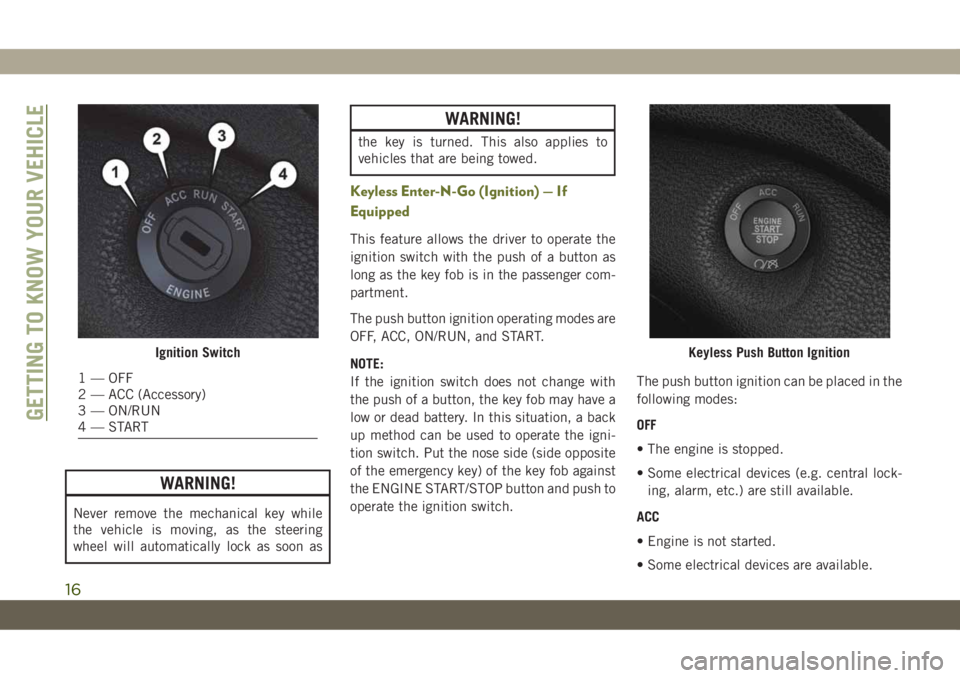
The push button ignition operating modes are
OFF, ACC, ON/RUN, and START.
NOTE:
If the ignition switch does not change with
the push of a button, the key fob may have a
low or dead battery. In this situation, a back
up method can be used to operate the igni-
tion switch. Put the nose side (side opposite
of the emergency key) of the key fob against
the ENGINE START/STOP button and push to
operate the ignition switch.The push button ignition can be placed in the
following modes:
OFF
• The engine is stopped.
• Some electrical devices (e.g. central lock-
ing, alarm, etc.) are still available.
ACC
• Engine is not started.
• Some electrical devices are available.
Ignition Switch
1 — OFF
2 — ACC (Accessory)
3 — ON/RUN
4—START
Keyless Push Button Ignition
GETTING TO KNOW YOUR VEHICLE
16
Page 19 of 344
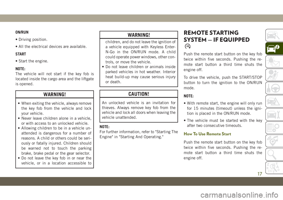
ON/RUN
• Driving position.
• All the electrical devices are available.
START
• Start the engine.
NOTE:
The vehicle will not start if the key fob is
located inside the cargo area and the liftgate
is opened.
WARNING!
• When exiting the vehicle, always remove
the key fob from the vehicle and lock
your vehicle.
• Never leave children alone in a vehicle,
or with access to an unlocked vehicle.
• Allowing children to be in a vehicle un-
attended is dangerous for a number of
reasons. A child or others could be seri-
ously or fatally injured. Children should
be warned not to touch the parking
brake, brake pedal or the gear selector.
• Do not leave the key fob in or near the
vehicle, or in a location accessible to
WARNING!
children, and do not leave the ignition of
a vehicle equipped with Keyless Enter-
N-Go in the ON/RUN mode. A child
could operate power windows, other con-
trols, or move the vehicle.
• Do not leave children or animals inside
parked vehicles in hot weather. Interior
heat build-up may cause serious injury
or death.
CAUTION!
An unlocked vehicle is an invitation for
thieves. Always remove key fob from the
vehicle and lock all doors when leaving the
vehicle unattended.
NOTE:
For further information, refer to "Starting The
Engine" in "Starting And Operating."
REMOTE STARTING
SYSTEM — IF EQUIPPED
Push the remote start button on the key fob
twice within five seconds. Pushing the re-
mote start button a third time shuts the
engine off.
To drive the vehicle, push the START/STOP
button to turn the ignition to the ON/RUN
mode.
NOTE:
• With remote start, the engine will only run
for 15 minutes (timeout) unless the igni-
tion is placed in the ON/RUN mode.
• The vehicle must be started with the key
after two consecutive timeouts.
How To Use Remote Start
Push the remote start button on the key fob
twice within five seconds. Pushing the re-
mote start button a third time shuts the
engine off.
17
Page 20 of 344
To drive the vehicle, push the unlock button,
insert the key in the ignition and turn to the
ON/RUN position.
NOTE:
• With remote start, the engine will only run
for 15 minutes (timeout) unless the igni-
tion key is placed in the ON/RUN position.
• The vehicle must be started with the key
after two consecutive timeouts.
All of the following conditions must be met
before the engine will remote start:
• Gear selector in PARK
• Doors closed
• Hood closed
• Liftgate closed
• Hazard switch off
• Brake switch inactive (brake pedal not
pushed)
• Battery at an acceptable charge level
• Check engine light shall not be present• System not disabled from previous remote
start event
• Vehicle alarm system indicator flashing
• Ignition in STOP/OFF position
• Fuel level meets minimum requirement
• Vehicle security alarm is not signaling an
intrusion
WARNING!
• Do not start or run an engine in a closed
garage or confined area. Exhaust gas
contains Carbon Monoxide (CO) which is
odorless and colorless. Carbon Monox-
ide is poisonous and can cause serious
injury or death when inhaled.
• Keep key fobs away from children. Op-
eration of the Remote Start System, win-
dows, door locks or other controls could
cause serious injury or death.
To Enter Remote Start Mode
Push and release the remote start button on
the key fob twice within five seconds. The
vehicle doors will lock, the parking lights will
flash, and the horn will chirp twice (if pro-
grammed). Then, the engine will start, and
the vehicle will remain in the Remote Start
mode for a 15-minute cycle.
NOTE:
• If an engine fault is present or fuel level is
low, the vehicle will start and then shut
down in 10 seconds.
• The park lamps will turn on and remain on
during Remote Start mode.
• For security, power window and power sun-
roof operation (if equipped) are disabled
when the vehicle is in the Remote Start
mode.
• The engine can be started two consecutive
times with the key fob. However, the igni-
tion must be cycled by pushing the START/
STOP button twice (or the ignition switch
must be cycled to the ON/RUN position)
before you can repeat the start sequence
for a third cycle.
GETTING TO KNOW YOUR VEHICLE
18
Page 64 of 344
INSTRUMENT CLUSTER
DISPLAY
Your vehicle may be equipped with an instru-
ment cluster display, which offers useful in-
formation to the driver. With the ignition in
the STOP/OFF mode, opening/closing of a
door will activate the display for viewing, and
display the total miles, or kilometers, in the
odometer. Your instrument cluster display is
designed to display important information
about your vehicle’s systems and features.
Using a driver interactive display located on
the instrument panel, your instrument clus-
ter display can show you how systems are
working and give you warnings when they
aren’t. The steering wheel mounted controls
allow you to scroll through and enter the main
menus and submenus. You can access the
specific information you want and make se-
lections and adjustments.
Instrument Cluster Display Location And
Controls
The instrument cluster display features a
driver-interactive display that is located in
the instrument cluster.
The instrument cluster display menu items
consist of the following:
• Speedometer
• Vehicle Info
• Driver Assist — If Equipped
• Fuel Economy
• Trip Info
• Stop/Start
• Audio
• Messages
• Screen Setup
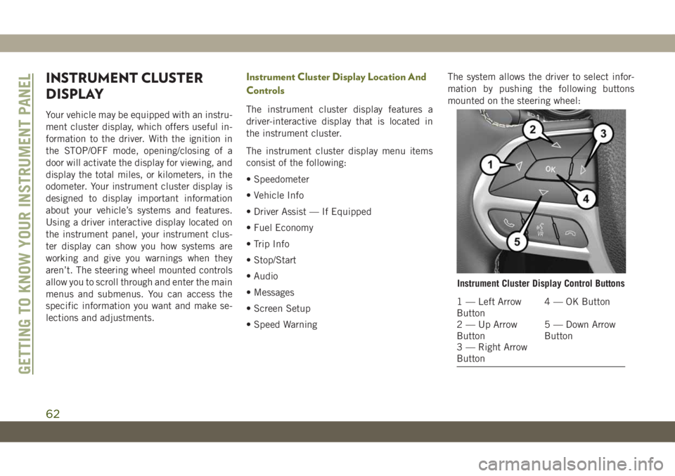
• Speed WarningThe system allows the driver to select infor-
mation by pushing the following buttons
mounted on the steering wheel:
Instrument Cluster Display Control Buttons
1 — Left Arrow
Button4 — OK Button
2 — Up Arrow
Button5 — Down Arrow
Button
3 — Right Arrow
Button
GETTING TO KNOW YOUR INSTRUMENT PANEL
62
Page 65 of 344
•Up Arrow Button
Push and release theuparrow button to
scroll upward through the main menu and
submenus.
•Down Arrow Button
Push and release thedownarrow button to
scroll downward through the main menu
and submenus.
•Right Arrow Button
Push and release therightarrow button to
access the information screens or submenu
screens of a main menu item.
•Left Arrow Button
Push and release theleftarrow button to
access the information screens or submenu
screens of a main menu item.
•OK Button
Push theOKbutton to access/select the
information screens or submenu screens of
a main menu item. Push and hold theOK
button to reset displayed/selected features
that can be reset.Instrument Cluster Display Selectable
Items
The instrument cluster display can be used to
view the following main menu items:
Speedometer Stop/Start
Vehicle Info Audio
Driver Assist Messages
Fuel Economy Screen Setup
Trip Gear Shift Indicator
(GSI)
NOTE:
Depending on the vehicles options, feature
settings may vary. Refer to the “Instrument
Cluster Display” in “Getting To know Your
Instrument Panel” in the Owner’s Manual for
further information.
Diesel Displays
When the appropriate conditions exist, the
following messages display in the instrument
cluster display:
• Exhaust Filter Nearing Full Safely Drive at
Consistent Speeds to Clear• Exhaust Filter Full – Power Reduced See
Dealer
• Exhaust System Service Required – See
Dealer
• Exhaust System – Filter XX% Full Service
Required See Dealer
• Exhaust System Regeneration in Process
Continue Driving
• Exhaust System – Regeneration Completed
Diesel Particulate Filter (DPF) Messages
This engine meets all required diesel engine
emissions standards. To achieve these emis-
sions standards, your vehicle is equipped
with a state-of-the-art engine and exhaust
system. These systems are seamlessly inte-
grated into your vehicle and managed by the
Powertrain Control Module (PCM). The PCM
manages engine combustion to allow the ex-
haust system’s catalyst to trap and burn Par-
ticulate Matter (PM) pollutants, with no input
or interaction on your part.
63
Page 66 of 344
WARNING!
A hot exhaust system can start a fire if you
park over materials that can burn. Such
materials might be grass or leaves coming
into contact with your exhaust system. Do
not park or operate your vehicle in areas
where your exhaust system can contact
anything that can burn.
CAUTION!
The engine may be switched off even if the
warning light is on: repeated interruptions
of the regeneration process could cause an
early deterioration of engine oil. For this
reason it is always advisable to wait for the
symbol to go off before turning off the
engine, following the instructions above.
Do not complete the DPF regeneration
process when the vehicle is stopped.
WARNING LIGHTS AND
MESSAGES
The warning/indicator lights will illuminate in
the instrument panel together with a dedi-
cated message and/or acoustic signal when
applicable. These indications are indicative
and precautionary and as such must not be
considered as exhaustive and/or alternative
to the information contained in the Owner’s
Manual, which you are advised to read care-
fully in all cases. Always refer to the informa-
tion in this chapter in the event of a failure
indication. All active telltales will display first
if applicable. The system check menu may
appear different based upon equipment op-
tions and current vehicle status. Some tell-
tales are optional and may not appear.
Red Warning Lights
— Seat Belt Reminder Warning Light
This warning light indicates when the driver
or passenger seat belt is unbuckled. When
the ignition is first placed in the ON/RUN or
ACC/ON/RUN position and if the driver’s seat
belt is unbuckled, a chime will sound and the
light will turn on. When driving, if the driver
or front passenger seat belt remains unbuck-
led, the Seat Belt Reminder Light will flash or
remain on continuously and a chime will
sound.
Refer to “Occupant Restraint Systems” in
“Safety” for further information.
— Air Bag Warning Light
This warning light will illuminate to indicate
a fault with the air bag, and will turn on for
four to eight seconds as a bulb check when
the ignition is placed in the ON/RUN or
ACC/ON/RUN position. This light will illumi-
nate with a single chime when a fault with the
air bag has been detected, it will stay on until
the fault is cleared. If the light is either not on
GETTING TO KNOW YOUR INSTRUMENT PANEL
64
Page 67 of 344
during startup, stays on, or turns on while
driving, have the system inspected at an
authorized dealer as soon as possible.
— Brake Warning Light
This warning light monitors various brake
functions, including brake fluid level and
parking brake application. If the brake light
turns on it may indicate that the parking
brake is applied, that the brake fluid level is
low, or that there is a problem with the
anti-lock brake system.
If the light remains on when the parking
brake has been disengaged, and the fluid
level is at the full mark on the master cylinder
reservoir, it indicates a possible brake hy-
draulic system malfunction or that a problem
with the Brake Booster has been detected by
the Anti-Lock Brake System (ABS) / Elec-
tronic Stability Control (ESC) system. In this
case, the light will remain on until the condi-
tion has been corrected. If the problem is
related to the brake booster, the ABS pump
will run when applying the brake, and a brake
pedal pulsation may be felt during each stop.The dual brake system provides a reserve
braking capacity in the event of a failure to a
portion of the hydraulic system. A leak in
either half of the dual brake system is indi-
cated by the Brake Warning Light, which will
turn on when the brake fluid level in the
master cylinder has dropped below a speci-
fied level.
The light will remain on until the cause is
corrected.
NOTE:
The light may flash momentarily during sharp
cornering maneuvers, which change fluid
level conditions. The vehicle should have
service performed, and the brake fluid level
checked.
If brake failure is indicated, immediate repair
is necessary.
WARNING!
Driving a vehicle with the red brake light
on is dangerous. Part of the brake system
may have failed. It will take longer to stop
WARNING!
the vehicle. You could have a collision.
Have the vehicle checked immediately.
Vehicles equipped with the Anti-Lock Brake
System (ABS) are also equipped with Elec-
tronic Brake Force Distribution (EBD). In the
event of an EBD failure, the Brake Warning
Light will turn on along with the ABS Light.
Immediate repair to the ABS system is re-
quired.
Operation of the Brake Warning Light can be
checked by turning the ignition switch from
the OFF position to the ON/RUN position.
The light should illuminate for approximately
four seconds. The light should then turn off
unless the parking brake is applied or a brake
fault is detected. If the light does not illumi-
nate, have the light inspected by an autho-
rized dealer.
The light also will turn on when the parking
brake is applied with the ignition switch in
the ON/RUN position.
65