instrument cluster JEEP CHEROKEE 2019 Owner handbook (in English)
[x] Cancel search | Manufacturer: JEEP, Model Year: 2019, Model line: CHEROKEE, Model: JEEP CHEROKEE 2019Pages: 344, PDF Size: 6.35 MB
Page 9 of 344
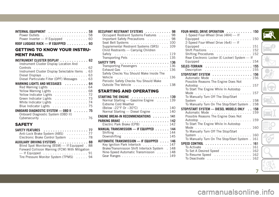
INTERNAL EQUIPMENT................. 58Power Outlets................... 58
Power Inverter — If Equipped......... 60
ROOF LUGGAGE RACK — IF EQUIPPED......... 60
GETTING TO KNOW YOUR INSTRU-
MENT PANEL
INSTRUMENT CLUSTER DISPLAY............ 62Instrument Cluster Display Location And
Controls....................... 62
Instrument Cluster Display Selectable Items . 63
Diesel Displays................... 63
Diesel Particulate Filter (DPF) Messages . . . 63
WARNING LIGHTS AND MESSAGES.......... 64Red Warning Lights................ 64
Yellow Warning Lights............... 68
Yellow Indicator Lights.............. 72
Green Indicator Lights.............. 73
White Indicator Lights.............. 74
Blue Indicator Lights............... 75
ONBOARD DIAGNOSTIC SYSTEM — OBD II...... 75Onboard Diagnostic System (OBD II)
Cybersecurity.................... 76
SAFETY
SAFETY FEATURES................... 77Anti-Lock Brake System (ABS)......... 77
Electronic Brake Control System........ 78
AUXILIARY DRIVING SYSTEMS............. 88Blind Spot Monitoring (BSM) — If Equipped . 88
Forward Collision Warning (FCW) With Mitigation
— If Equipped................... 91
Tire Pressure Monitor System (TPMS)..... 94
OCCUPANT RESTRAINT SYSTEMS........... 98Occupant Restraint Systems Features..... 98
Important Safety Precautions.......... 98
Seat Belt Systems................ 100
Supplemental Restraint Systems (SRS) . . . 109
Child Restraints — Carrying Children
Safely....................... 119
Transporting Pets................ 135
SAFETY TIPS..................... 136Transporting Passengers............ 136
Exhaust Gas................... 136
Safety Checks You Should Make Inside The
Vehicle...................... 136
Periodic Safety Checks You Should Make
Outside The Vehicle............... 138
STARTING AND OPERATING
STARTING THE ENGINE................ 139Normal Starting — Gasoline Engine..... 139
Extreme Cold Weather
(Below –22°F Or −30°C)............ 140
Normal Starting — Diesel Engine....... 140
ENGINE BREAK-IN RECOMMENDATIONS....... 141
PARKING BRAKE.................... 142
Electric Park Brake (EPB)........... 142
MANUAL TRANSMISSION — IF EQUIPPED...... 144Shifting...................... 144
Downshifting................... 145
AUTOMATIC TRANSMISSION — IF EQUIPPED.... 146Key Ignition Park Interlock........... 147
Brake/Transmission Shift Interlock System . 148
Nine-Speed Automatic Transmission..... 148
Gear Ranges.................... 149
FOUR-WHEEL DRIVE OPERATION........... 1501-Speed Four-Wheel Drive (4X4) — If
Equipped..................... 150
2-Speed Four-Wheel Drive (4x4) — If
Equipped..................... 151
Shift Positions.................. 152
Shifting Procedures............... 152
Rear Electronic Locker (E-Locker) System — If
Equipped..................... 154
SELEC-TERRAIN.................... 155Description.................... 155
STOP/START SYSTEM................. 156Automatic Mode................. 156
Possible Reasons The Engine Does Not
Autostop...................... 157
To Start The Engine While In Autostop
Mode........................ 157
To Manually Turn Off The Stop/Start
System...................... 158
To Manually Turn On The Stop/Start System . 158
STOP/START SYSTEM — DIESEL MODELS ONLY . . 158Automatic Mode................. 159
Possible Reasons The Engine Does Not
Autostop...................... 159
To Start The Engine While In Autostop
Mode........................ 160
To Manually Turn Off The Stop/Start
System....................... 160
To Manually Turn On The Stop/Start System . 161
SPEED CONTROL.................... 161To Activate.................... 161
To Set A Desired Speed............. 162
To Resume Speed................ 162
To Deactivate................... 162
7
Page 13 of 344
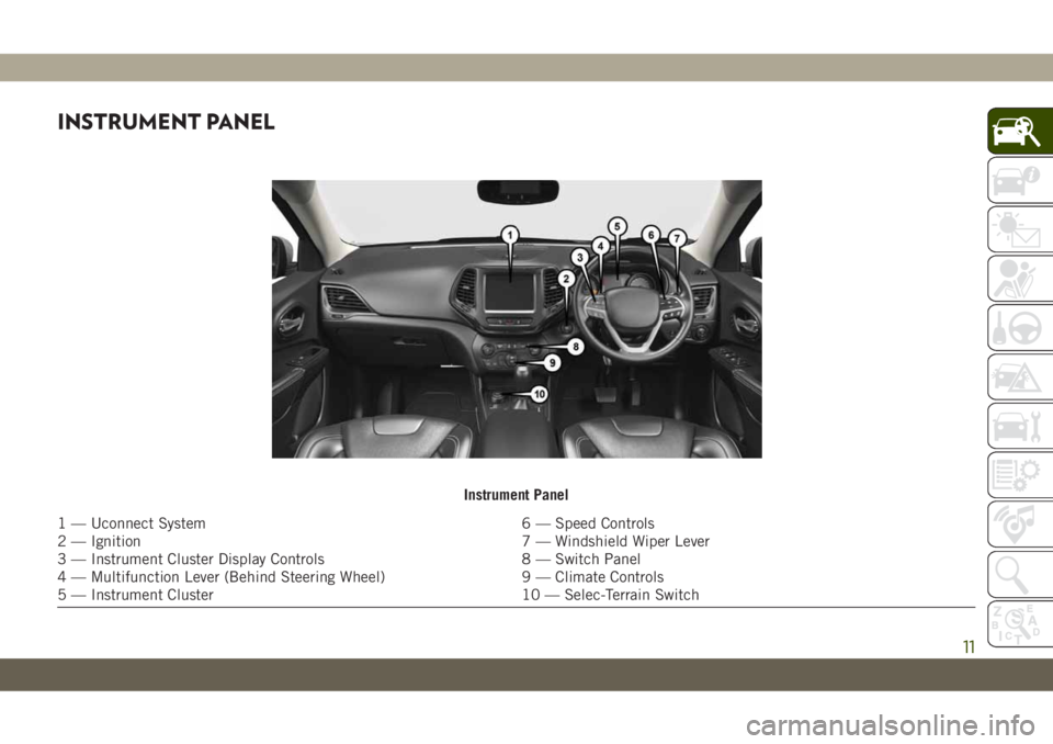
INSTRUMENT PANEL
Instrument Panel
1 — Uconnect System 6 — Speed Controls
2 — Ignition 7 — Windshield Wiper Lever
3 — Instrument Cluster Display Controls 8 — Switch Panel
4 — Multifunction Lever (Behind Steering Wheel) 9 — Climate Controls
5 — Instrument Cluster 10 — Selec-Terrain Switch
11
Page 16 of 344
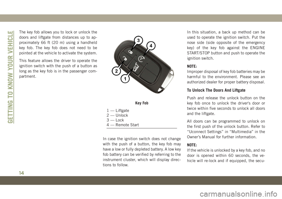
The key fob allows you to lock or unlock the
doors and liftgate from distances up to ap-
proximately 66 ft (20 m) using a handheld
key fob. The key fob does not need to be
pointed at the vehicle to activate the system.
This feature allows the driver to operate the
ignition switch with the push of a button as
long as the key fob is in the passenger com-
partment.
In case the ignition switch does not change
with the push of a button, the key fob may
have a low or fully depleted battery. A low key
fob battery can be verified by referring to the
instrument cluster, which will display direc-
tions to follow.In this situation, a back up method can be
used to operate the ignition switch. Put the
nose side (side opposite of the emergency
key) of the key fob against the ENGINE
START/STOP button and push to operate the
ignition switch.
NOTE:
Improper disposal of key fob batteries may be
harmful to the environment. Please see an
authorized dealer for proper battery disposal.
To Unlock The Doors And Liftgate
Push and release the unlock button on the
key fob once to unlock the driver's door or
twice within five seconds to unlock all doors
and the liftgate.
All doors can be programmed to unlock on
the first push of the unlock button. Refer to
“Uconnect Settings” in “Multimedia” in the
Owner’s Manual for further information.
NOTE:
If the vehicle is unlocked by a key fob, and no
door is opened within 60 seconds, the ve-
hicle will re-lock and if equipped, the secu-
Key Fob
1 — Liftgate
2 — Unlock
3 — Lock
4 — Remote Start
GETTING TO KNOW YOUR VEHICLE
14
Page 21 of 344
VEHICLE SECURITY ALARM
— IF EQUIPPED
The vehicle security alarm monitors the ve-
hicle doors, hood, liftgate, and the Keyless
Enter-N-Go — Ignition for unauthorized op-
eration. While the vehicle security alarm is
armed, interior switches for door locks and
liftgate release are disabled. If something
triggers the alarm, the vehicle security alarm
will provide the following audible and visible
signals:
• The horn will pulse.
• The turn signals will flash.
• The vehicle security light in the instrument
cluster will flash.
To Arm The System
Follow these steps to arm the vehicle security
alarm:
1. Make sure the vehicle’s ignition is placed
in the “OFF” mode.
• For vehicles equipped with Keyless En-
try, make sure the vehicle’s keyless
ignition system is OFF.2. Perform one of the following methods to
lock the vehicle:
• Push the lock button on the interior
power door lock switch with the driver
and/or passenger door open.
• Push the lock button on the exterior
Passive Entry Door Handle with a valid
key fob available in the same exterior
zone. Refer to "Doors" in "Getting To
Know Your Vehicle" in your Owner’s
Manual for further information.
• Push the lock button on the key fob.
3. If any doors are open, close them.
To Disarm The System
The vehicle security alarm can be disarmed
using any of the following methods:
• Push the unlock button on the key fob.
• Grasp the passive entry door handle to
unlock the door, refer to "Doors" in "Getting
To Know Your Vehicle" in your Owner’s
Manual for further information.
• Cycle the ignition out of the off mode to
disarm the system.NOTE:
• The driver's door key cylinder and the lift-
gate button on the key fob cannot arm or
disarm the vehicle security alarm.
• The vehicle security alarm remains armed
during power liftgate entry. Pushing the
liftgate button will not disarm the vehicle
security alarm. If someone enters the ve-
hicle through the liftgate and opens any
door, the alarm will sound.
• When the vehicle security alarm is armed,
the interior power door lock switches will
not unlock the doors.
The vehicle security alarm is designed to
protect your vehicle. However, you can create
conditions where the system will give you a
false alarm. If one of the previously described
arming sequences has occurred, the vehicle
security alarm will arm, regardless of whether
you are in the vehicle or not. If you remain in
the vehicle and open a door, the alarm will
sound. If this occurs, disarm the vehicle
security alarm.
If the vehicle security alarm is armed and the
battery becomes disconnected, the vehicle
security alarm will remain armed when the
19
Page 27 of 344
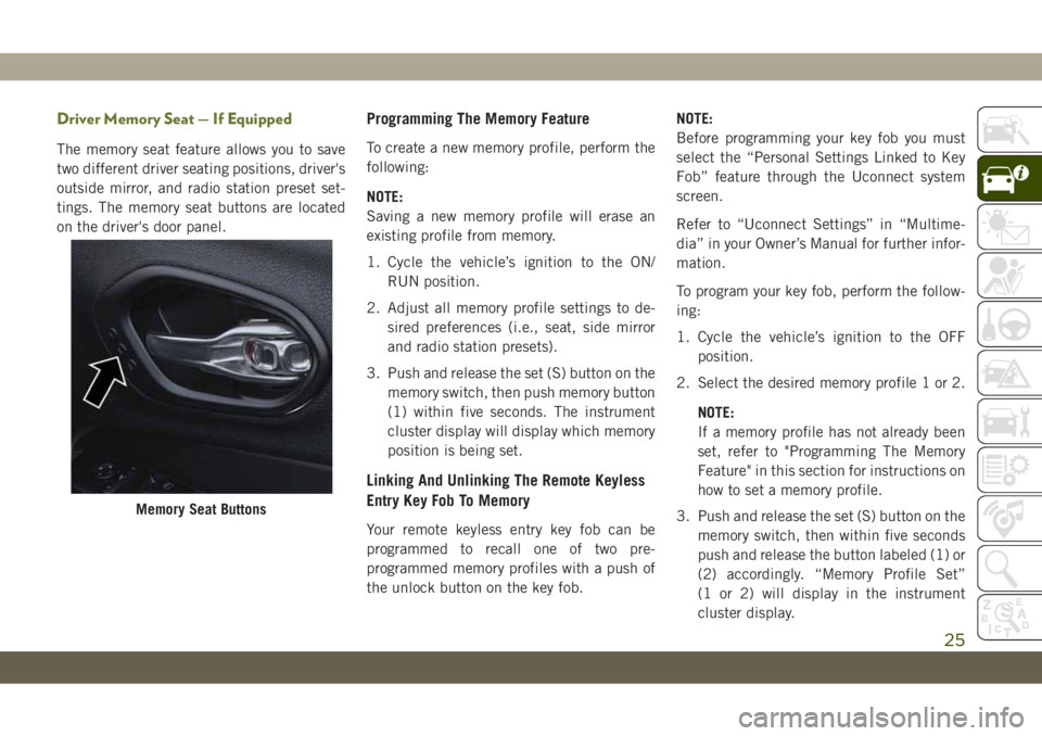
Driver Memory Seat — If Equipped
The memory seat feature allows you to save
two different driver seating positions, driver's
outside mirror, and radio station preset set-
tings. The memory seat buttons are located
on the driver's door panel.
Programming The Memory Feature
To create a new memory profile, perform the
following:
NOTE:
Saving a new memory profile will erase an
existing profile from memory.
1. Cycle the vehicle’s ignition to the ON/
RUN position.
2. Adjust all memory profile settings to de-
sired preferences (i.e., seat, side mirror
and radio station presets).
3. Push and release the set (S) button on the
memory switch, then push memory button
(1) within five seconds. The instrument
cluster display will display which memory
position is being set.
Linking And Unlinking The Remote Keyless
Entry Key Fob To Memory
Your remote keyless entry key fob can be
programmed to recall one of two pre-
programmed memory profiles with a push of
the unlock button on the key fob.NOTE:
Before programming your key fob you must
select the “Personal Settings Linked to Key
Fob” feature through the Uconnect system
screen.
Refer to “Uconnect Settings” in “Multime-
dia” in your Owner’s Manual for further infor-
mation.
To program your key fob, perform the follow-
ing:
1. Cycle the vehicle’s ignition to the OFF
position.
2. Select the desired memory profile 1 or 2.
NOTE:
If a memory profile has not already been
set, refer to "Programming The Memory
Feature" in this section for instructions on
how to set a memory profile.
3. Push and release the set (S) button on the
memory switch, then within five seconds
push and release the button labeled (1) or
(2) accordingly. “Memory Profile Set”
(1 or 2) will display in the instrument
cluster display.
Memory Seat Buttons
25
Page 38 of 344
Front And Rear Fog Lights — If Equipped
The fog light switches are built into the head-
light switch.
NOTE:
If the vehicle is only equipped with rear fog
lights, only a single button will be available in
the center of the headlight switch. Push once
to turn the rear fog lights on, and a second
time to turn them off.
To activate the front fog lights, push the
upper half of the headlight switch. To turn off
the front fog lights, push the upper half of the
headlight switch a second time.
NOTE:
To activate the front fog lights, the parking
lights or low beam headlights must first be
activated.
To activate the rear fog lights, push the
lower half of the headlight switch. To turn off
the rear fog lights, push the lower half of the
headlight switch a second time.NOTE:
To turn on the rear fog lights, the low beam
headlights or front fog lights must first be
active.
An indicator light in the instrument cluster
illuminates when the fog lights are turned on.
Turn Signals
Move the multifunction lever up or down and
the arrows on each side of the instrument
cluster display will flash to show proper op-
eration of the front and rear turn signal lights.
NOTE:
• If either light remains on and does not
flash, or there is a very fast flash rate, check
for a defective LED turn signal in the head-
lamp. Please see an authorized dealer for
service.
• When the Daytime Running Lights are on
and a turn signal is activated, the Daytime
Running Lamp will turn off on the side of
the vehicle in which the turn signal is
flashing. The Daytime Running Lamp will
turn back on when the turn signal is turned
off.
Automatic Headlight Leveling — HID
Headlights Only
This feature prevents the headlights from
interfering with the vision of oncoming driv-
ers. Headlight leveling automatically adjusts
the height of the headlight beam in reaction
to changes in vehicle pitch.
Battery Saver
To protect the life of your vehicle’s battery,
load shedding is provided for both the interior
and exterior lights.
If the ignition is OFF and any door is left ajar
for 10 minutes or the dimmer control is
rotated all the way up to the dome on position
for 10 minutes, the interior lights will auto-
matically turn off.
NOTE:
Battery saver mode is canceled if the ignition
is ON.
If the headlights remain on while the ignition
is cycled OFF, the exterior lights will auto-
matically turn off after eight minutes. If the
GETTING TO KNOW YOUR VEHICLE
36
Page 64 of 344
INSTRUMENT CLUSTER
DISPLAY
Your vehicle may be equipped with an instru-
ment cluster display, which offers useful in-
formation to the driver. With the ignition in
the STOP/OFF mode, opening/closing of a
door will activate the display for viewing, and
display the total miles, or kilometers, in the
odometer. Your instrument cluster display is
designed to display important information
about your vehicle’s systems and features.
Using a driver interactive display located on
the instrument panel, your instrument clus-
ter display can show you how systems are
working and give you warnings when they
aren’t. The steering wheel mounted controls
allow you to scroll through and enter the main
menus and submenus. You can access the
specific information you want and make se-
lections and adjustments.
Instrument Cluster Display Location And
Controls
The instrument cluster display features a
driver-interactive display that is located in
the instrument cluster.
The instrument cluster display menu items
consist of the following:
• Speedometer
• Vehicle Info
• Driver Assist — If Equipped
• Fuel Economy
• Trip Info
• Stop/Start
• Audio
• Messages
• Screen Setup
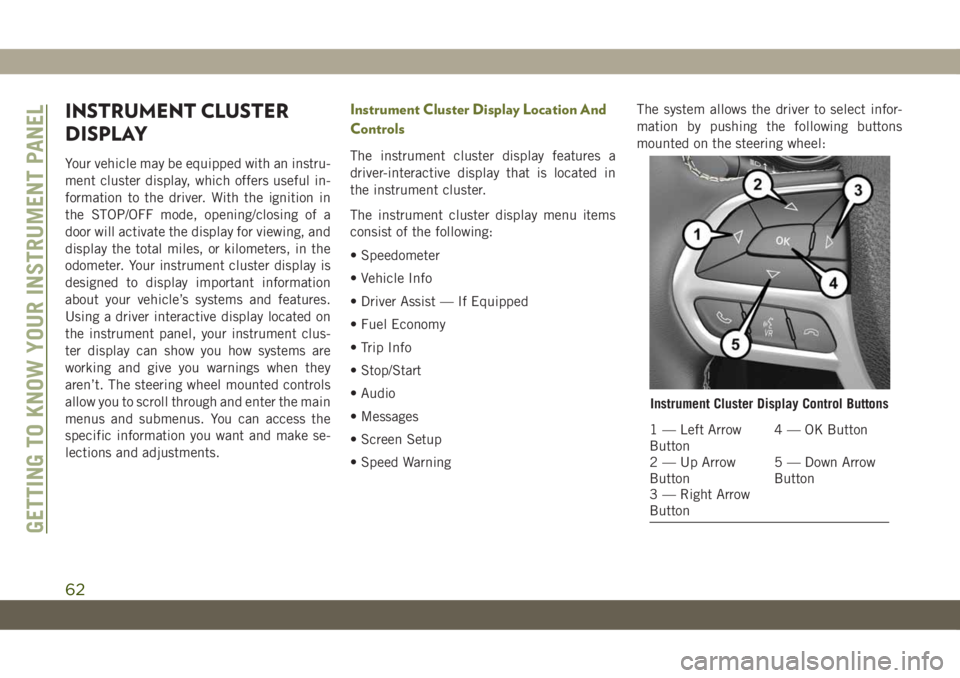
• Speed WarningThe system allows the driver to select infor-
mation by pushing the following buttons
mounted on the steering wheel:
Instrument Cluster Display Control Buttons
1 — Left Arrow
Button4 — OK Button
2 — Up Arrow
Button5 — Down Arrow
Button
3 — Right Arrow
Button
GETTING TO KNOW YOUR INSTRUMENT PANEL
62
Page 65 of 344
•Up Arrow Button
Push and release theuparrow button to
scroll upward through the main menu and
submenus.
•Down Arrow Button
Push and release thedownarrow button to
scroll downward through the main menu
and submenus.
•Right Arrow Button
Push and release therightarrow button to
access the information screens or submenu
screens of a main menu item.
•Left Arrow Button
Push and release theleftarrow button to
access the information screens or submenu
screens of a main menu item.
•OK Button
Push theOKbutton to access/select the
information screens or submenu screens of
a main menu item. Push and hold theOK
button to reset displayed/selected features
that can be reset.Instrument Cluster Display Selectable
Items
The instrument cluster display can be used to
view the following main menu items:
Speedometer Stop/Start
Vehicle Info Audio
Driver Assist Messages
Fuel Economy Screen Setup
Trip Gear Shift Indicator
(GSI)
NOTE:
Depending on the vehicles options, feature
settings may vary. Refer to the “Instrument
Cluster Display” in “Getting To know Your
Instrument Panel” in the Owner’s Manual for
further information.
Diesel Displays
When the appropriate conditions exist, the
following messages display in the instrument
cluster display:
• Exhaust Filter Nearing Full Safely Drive at
Consistent Speeds to Clear• Exhaust Filter Full – Power Reduced See
Dealer
• Exhaust System Service Required – See
Dealer
• Exhaust System – Filter XX% Full Service
Required See Dealer
• Exhaust System Regeneration in Process
Continue Driving
• Exhaust System – Regeneration Completed
Diesel Particulate Filter (DPF) Messages
This engine meets all required diesel engine
emissions standards. To achieve these emis-
sions standards, your vehicle is equipped
with a state-of-the-art engine and exhaust
system. These systems are seamlessly inte-
grated into your vehicle and managed by the
Powertrain Control Module (PCM). The PCM
manages engine combustion to allow the ex-
haust system’s catalyst to trap and burn Par-
ticulate Matter (PM) pollutants, with no input
or interaction on your part.
63
Page 70 of 344
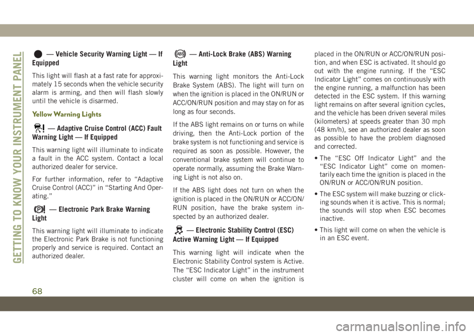
— Vehicle Security Warning Light — If
Equipped
This light will flash at a fast rate for approxi-
mately 15 seconds when the vehicle security
alarm is arming, and then will flash slowly
until the vehicle is disarmed.
Yellow Warning Lights
— Adaptive Cruise Control (ACC) Fault
Warning Light — If Equipped
This warning light will illuminate to indicate
a fault in the ACC system. Contact a local
authorized dealer for service.
For further information, refer to “Adaptive
Cruise Control (ACC)” in “Starting And Oper-
ating.”
— Electronic Park Brake Warning
Light
This warning light will illuminate to indicate
the Electronic Park Brake is not functioning
properly and service is required. Contact an
authorized dealer.
— Anti-Lock Brake (ABS) Warning
Light
This warning light monitors the Anti-Lock
Brake System (ABS). The light will turn on
when the ignition is placed in the ON/RUN or
ACC/ON/RUN position and may stay on for as
long as four seconds.
If the ABS light remains on or turns on while
driving, then the Anti-Lock portion of the
brake system is not functioning and service is
required as soon as possible. However, the
conventional brake system will continue to
operate normally, assuming the Brake Warn-
ing Light is not also on.
If the ABS light does not turn on when the
ignition is placed in the ON/RUN or ACC/ON/
RUN position, have the brake system in-
spected by an authorized dealer.
— Electronic Stability Control (ESC)
Active Warning Light — If Equipped
This warning light will indicate when the
Electronic Stability Control system is Active.
The “ESC Indicator Light” in the instrument
cluster will come on when the ignition isplaced in the ON/RUN or ACC/ON/RUN posi-
tion, and when ESC is activated. It should go
out with the engine running. If the “ESC
Indicator Light” comes on continuously with
the engine running, a malfunction has been
detected in the ESC system. If this warning
light remains on after several ignition cycles,
and the vehicle has been driven several miles
(kilometers) at speeds greater than 30 mph
(48 km/h), see an authorized dealer as soon
as possible to have the problem diagnosed
and corrected.
• The “ESC Off Indicator Light” and the
“ESC Indicator Light” come on momen-
tarily each time the ignition is placed in the
ON/RUN or ACC/ON/RUN position.
• The ESC system will make buzzing or click-
ing sounds when it is active. This is normal;
the sounds will stop when ESC becomes
inactive.
• This light will come on when the vehicle is
in an ESC event.
GETTING TO KNOW YOUR INSTRUMENT PANEL
68
Page 72 of 344
CAUTION!
could affect fuel economy and driveability.
If the MIL is flashing, severe catalytic
converter damage and power loss will soon
occur. Immediate service is required.
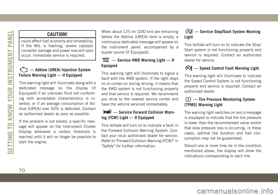
— Adblue (UREA) Injection System
Failure Warning Light — If Equipped
This warning light will illuminate along with a
dedicated message on the display (If
Equipped) if an unknown fluid not conform-
ing with acceptable characteristics is in-
serted, or if an average consumption of Ad-
blue (UREA) over 50% is detected. Contact
an authorized dealer as soon as possible.
If the problem is not solved, a specific mes-
sage will appear on the Instrument Cluster
Display whenever a certain threshold is
reached until it will no longer be possible to
start the engine.When about 125 mi (200 km) are remaining
before the Adblue (UREA) tank is empty, a
continuous dedicated message will appear on
the instrument panel, accompanied by a
buzzer sound (If Equipped).
SERV4WD— Service 4WD Warning Light — If
Equipped
This warning light will illuminate to signal a
fault with the 4WD system. If the light stays
on or comes on during driving, it means that
the 4WD system is not functioning properly
and that service is required. We recommend
you drive to the nearest service center and
have the vehicle serviced immediately.
— Service Forward Collision Warn-
ing (FCW) Light — If Equipped
This telltale will turn on to indicate a fault in
the Forward Collision Warning System. Con-
tact your local authorized dealer for service.
Refer to "Forward Collision Warning (FCW)" in
"Safety" for further information.
— Service Stop/Start System Warning
Light
This telltale will turn on to indicate the Stop/
Start system is not functioning properly and
service is required. Contact an authorized
dealer for service.
— Speed Control Fault Warning Light
This warning light will illuminate to indicate
the Speed Control System is not functioning
properly and service is required. Contact an
authorized dealer.
— Tire Pressure Monitoring System
(TPMS) Warning Light
The warning light switches on and a message
is displayed to indicate that the tire pressure
is lower than the recommended value and/or
that slow pressure loss is occurring. In these
cases, optimal tire duration and fuel con-
sumption may not be guaranteed.
Should one or more tires be in the condition
mentioned above, the display will show the
indications corresponding to each tire.
GETTING TO KNOW YOUR INSTRUMENT PANEL
70